NUMBER: 3 10–09 S.M. REF.: Listed in Table 1 ENGINE ... - ddcsn
NUMBER: 3 10–09 S.M. REF.: Listed in Table 1 ENGINE ... - ddcsn
NUMBER: 3 10–09 S.M. REF.: Listed in Table 1 ENGINE ... - ddcsn

You also want an ePaper? Increase the reach of your titles
YUMPU automatically turns print PDFs into web optimized ePapers that Google loves.
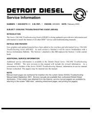
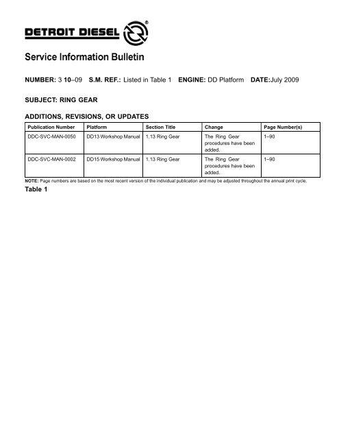
<strong>NUMBER</strong>: 3 10–09 S.M. <strong>REF</strong>.: <strong>Listed</strong> <strong>in</strong> <strong>Table</strong> 1 <strong>ENGINE</strong>: DD Platform DATE:July 2009SUBJECT: RING GEARADDITIONS, REVISIONS, OR UPDATESPublication Number Platform Section Title Change Page Number(s)DDC-SVC-MAN-0050 DD13 Workshop Manual 1.13 R<strong>in</strong>g Gear The R<strong>in</strong>g Gearprocedures have beenadded.1–90DDC-SVC-MAN-0002 DD15 Workshop Manual 1.13 R<strong>in</strong>g Gear The R<strong>in</strong>g Gearprocedures have beenadded.NOTE: Page numbers are based on the most recent version of the <strong>in</strong>dividual publication and may be adjusted throughout the annual pr<strong>in</strong>t cycle.<strong>Table</strong> 11–90
RING GEARThe steel r<strong>in</strong>g gear (1) and flywheel (2) is a two-piece assembly. Prior to assembly, the r<strong>in</strong>g gear isheated to expand its diameter. It is then <strong>in</strong>stalled onto the flywheelandallowedtocool.Asther<strong>in</strong>ggearcools, it contracts onto the flywheel, and locks <strong>in</strong> place.INSPECTION OF RING GEARIf <strong>in</strong>spection of the flywheel <strong>in</strong>dicates that r<strong>in</strong>g gear replacement is necessary, follow the belowprocedure.REMOVAL OF RING GEARRemove the r<strong>in</strong>g gear as follows:1. Shut off the eng<strong>in</strong>e, apply the park<strong>in</strong>g brake, chock the wheels, and perform any otherapplicable safety steps.2. Remove the transmission.3. Remove the flywheel. Refer to Section “Removal and Clean<strong>in</strong>g of Flywheel.”BURNSTo avoid <strong>in</strong>jury from burn<strong>in</strong>g, use lift<strong>in</strong>g tools andheat-resistant gloves when handl<strong>in</strong>g heated components.4. Us<strong>in</strong>g an acetylene torch, cut the r<strong>in</strong>g gear 1/2 to 3/4 of the way through, without allow<strong>in</strong>g theflame to touch the flywheel.5. The uncut portion will now yield. Tap the r<strong>in</strong>g gear to remove it from the flywheel.
INSTALLATION OF RING GEARInstall the r<strong>in</strong>g gear as follows:1. Support the flywheel, r<strong>in</strong>g gear side up, on a solid flat surface.BURNSTo avoid <strong>in</strong>jury from burn<strong>in</strong>g, use lift<strong>in</strong>g tools andheat-resistant gloves when handl<strong>in</strong>g heated components.NOTICE:Do not, under any circumstances, heat the gear over 204°C(399°F). Excessive heat may destroy the orig<strong>in</strong>al heat treatment.Heat treat<strong>in</strong>g “crayons” which are placed on the r<strong>in</strong>g gear and meltat a predeterm<strong>in</strong>ed temperature, may be obta<strong>in</strong>ed from most toolvendors. Use of these “crayons” will ensure aga<strong>in</strong>st overheat<strong>in</strong>gthe gear.2. Rest the r<strong>in</strong>g gear on a FLAT METAL SURFACE, and heat the gear uniformly with anacetylene torch, keep<strong>in</strong>g the torch mov<strong>in</strong>g around the gear to avoid hot spots.3. Use a pair of tongs to place the r<strong>in</strong>g gear on the flywheel with the chamfer, if any, fac<strong>in</strong>g thesame direction as on the gear just removed.4. Tap the r<strong>in</strong>g gear <strong>in</strong> place aga<strong>in</strong>st the shoulder of the flywheel. If the r<strong>in</strong>g gear cannot be tapped<strong>in</strong>to place readily so that it is seated all the way around, remove it, and apply additional heat.5. Install the flywheel. Refer to Section “Installation of Flywheel.”6. Install the transmission.
ADDITIONAL SERVICE INFORMATIONAdditional service <strong>in</strong>formation is available <strong>in</strong> Power Service Literature.Detroit Diesel®, DDC®, Series 60® and the sp<strong>in</strong>n<strong>in</strong>g arrows design are registered trademarks of Detroit Diesel Corporation.© Copyright 2009 Detroit Diesel Corporation. All rights reserved. Pr<strong>in</strong>ted <strong>in</strong> U.S.A.