
Create successful ePaper yourself
Turn your PDF publications into a flip-book with our unique Google optimized e-Paper software.
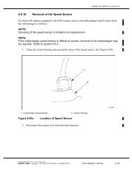
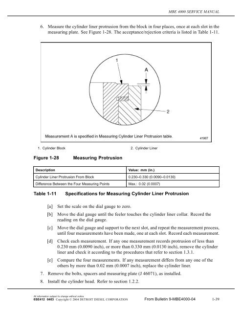
MBE 4000 SERVICE MANUAL6. Measure the cylinder liner protrusion from the block in four places, once at each slot in themeasuring plate. See Figure 1-28. The acceptance/rejection criteria is listed in Table 1-11.1. Cylinder Block 2. Cylinder LinerFigure 1-28Measuring ProtrusionDescriptionValue: mm (in.)Cylinder Liner Protrusion From Block 0.230–0.330 (0.0090–0.0130)Difference Between the Four Measuring Points Max.: 0.02 (0.0007)Table 1-11Specifications for Measuring Cylinder Liner Protrusion[a] Set the scale on the dial gauge to zero.[b] Move the dial gauge until the feeler touches the cylinder liner collar. Record thereading on the dial gauge.[c] Move the dial gauge and support to the next slot, and repeat the measurement process,until four measurements have been made, one at each slot. Record each measurement.[d] Check each measurement. If any one measurement records protrusion of less than0.230 mm (0.0090 inch), or more than 0.330 mm (0.0130 inch), remove the cylinderliner and check it according to the procedures that refer to section 1.3.1.[e] Compare the four measurements. If any measurement differs from any one of theothers by more than 0.02 mm (0.0007 inch), replace the cylinder liner.7. Remove the bolts, spacers and measuring plate (J 46071), as installed.8. Install the cylinder head. Refer to section 1.2.2.All information subject to change without notice.6SE412 0403 Copyright © 2004 DETROIT DIESEL CORPORATION From Bulletin 9-MBE4000-04 1-39
1.3 CYLINDER BLOCK1.3.2.3 Fuel System Leak TestPerform the following procedure to ensure that the fuel gallery is properly sealed and does notleak.NOTE:This procedure can be performed with the engine installed or removed from the vehicle.FIRETo avoid injury from fire, keep all potential ignition sourcesaway from diesel fuel, including open flames, sparks, andelectrical resistance heating elements. Do not smoke whenrefueling.1. Drain all fuel from engine.2. Rem ove a ll s ix inje ctor unit pum ps from the e ngine block. Re fe r to se ction 2.1.1.All information subject to change without notice.1-40 From Bulletin 9-MBE4000-04 6SE412 0403 Copyright © 2004 DETROIT DIESEL CORPORATION
MBE 4000 SERVICE MANUAL3. Install all six dummy unit pumps (J 45982-6-1), from the Head and Block Leak TesterTool Kit ( J 45982). S ee Figure 1-28a.1. Fuel Gallery Inlet 3. Fuel Gallery Outlet2. Pressure Gauge FittingF igu re 1-28aInstallin g D um my Injector Unit Pu mp sNOTE:One of the dummy unit pumps has a fitting for pressure gauge installation and it mustbe installed at the easiest position for gauge installation.4. Block the fuel gallery inlet and outlet with special plugs from kit (J 45982).S ee F igure 1-28a.5. Install the pressure gauge assembly (pressure gauge, pressure regulator, and shut offvalve) from kit ( J 45982). S ee F igure 1-28b.All information subject to change without notice.6 S E 4 12 04 03 Copyright © 2004 DET ROIT DIES EL CORP ORATION Fr o m B ullet in 9-M B E4 000-04 1-40a
1.3 CYLINDER BLOCK6. Connect a compressed air supply to the pressure gauge assembly.1. Pressure Gauge on Dummy Unit PumpFig ur e 1-28bIn stalling P ressu re G au ge Assemb ly to D u mmy U nit Pu mpEYE INJURYTo avoid injury from flying debris when using compressedair, wear adequate eye protection (face shield or safetygoggles) and do not exceed 40 psi (276 kPa) air pressure.7. Pressurize the system with 2 bar (29 psi). Use the pressure regulator to set the pressure.8. Check for leaks around the dummy unit pumps and inlet/outlet plugs using a soapsolution. Eliminate leaks.9. Close the shut off valve.10. Watch the pressure for 30 seconds. If the pressure holds at 2 bar (29 psi), the fuel galleryis properly sealing. In case of a pressure drop, the engine block should not be reused.1-40b F ro m B ullet in 9-M B E4 000-04 6 S E 4 12 04 03All information subject to change without notice.Copyright © 2004 DET ROIT DIES EL CORP ORATION
MBE 4000 SERVICE MANUAL1.3.2.4 Cylinder Block Leak TestPerform the following steps to conduct a cylinder block leak test to see if the engine block isleaking coolant.NOTE:This procedure can only be performed with the engine removed from the vehicle andusing only the engine block with the liners installed.1. Place the engine block with installed liners on the engine stand.2. Install all six top block cover plates(J 45982-1) from the Head and Block Leak Test kit(J 45982) using the s pecial bolts s upplie d.S ee F igure 1-28c.1. Block Cover Plates (6) - part of kit J 45982 3. Pressure Gauge Fitting2. Water Pump Cover Plate - part of kit J 45982 4. Oil Cooler/Filter Housing Cover Plate - part of kitJ 45982F igu re 1-28cInstallin g Block Cover Plates3. Install the oil cooler/filter housing cover plate, from the kit, on the right hand side of theengine block using supplied ha rdwa re. S ee F igure 1-28c.4. Install the water pump cover plate, from the kit, on the front of the engine using suppliedhardware. S ee Figure 1-28c.NOTE:The water pump cover plate has a fitting for installing the supplied pressure gauge.All information subject to change without notice.6 S E 4 12 04 03 Copyright © 2004 DET ROIT DIES EL CORP ORATION Fr o m B ullet in 9-M B E4 000-04 1-40c
MBE 4000 SERVICE MANUAL6. Install the pressure gauge assembly (pressure gauge, pressure regulator, and shut offvalve) from kit ( J 45982). S ee F igure 1-28e.1. Pressure Gauge AssemblyF igu re 1-28eInstallin g Pressure Gau g e Assemb ly7. C onnect a c om pres se d air supply to the pres sure gauge ass em bly. S ee F igure 1-28e.EYE INJURYTo avoid injury from flying debris when using compressedair, wear adequate eye protection (face shield or safetygoggles) and do not exceed 40 psi (276 kPa) air pressure.8. Pressurize the system with 2 bar (29 psi). Use the pressure regulator to set the pressure.9. Check for leaks around the all cover plates and plugs using a soap solution. Eliminateleaks.10. Close the shut off valve.11. Watch the pressure for 30 seconds. If the pressure holds at the 2 bar (29 psi), the cylinderblock coolant system is properly sealed. In case of a pressure drop, the engine blockshould not be reused.All information subject to change without notice.6 S E 4 12 04 03 Copyright © 2004 DET ROIT DIES EL CORP ORATION Fr o m B ullet in 9-M B E4 000-04 1-40e
1.4 EGR CYLINDER HEAD AND BLOCK1.4 EGR CYLINDER HEAD AND BLOCKThere are several minor changes in the cylinder liner, block and engine lifter brackets between theMBE 4000 EGR engine and the non-EGR engine.1.4.1 EGR Cylinder Head InstallationBe aware of the following notice when installing the cylinder head on an EGR engine:NOTICE:Be sure the carbon scraper ring is seated in the groove on thetop part of the cylinder liner before installing a new cylinder headgasket and the cylinder head, otherwise component damage canresult. See Figure 1-29.1. Cylinder Liner 3. Installed Piston2. Carbon Scraper Ring 4. Carbon Scraper Ring located in groove in cylinderlinerFig ure 1-29In stalled Carb on S cr aper Rin gNOTE:All remaining installation procedures for the cylinder head are identical to anon-EGR engine.1-40f F ro m B ullet in 9-M B E4 000-04 6 S E 4 12 04 03All information subject to change without notice.Copyright © 2004 DET ROIT DIES EL CORP ORATION