RADISSON BLU â SAFARI LODGE HOTEL â KRUGER ... - SANParks
RADISSON BLU â SAFARI LODGE HOTEL â KRUGER ... - SANParks
RADISSON BLU â SAFARI LODGE HOTEL â KRUGER ... - SANParks

You also want an ePaper? Increase the reach of your titles
YUMPU automatically turns print PDFs into web optimized ePapers that Google loves.
<strong>RADISSON</strong> <strong>BLU</strong> – <strong>SAFARI</strong> <strong>LODGE</strong> <strong>HOTEL</strong> – <strong>KRUGER</strong> NATIONALPARKELECTRONIC SERVICES / ICT CONCEPT DESIGN REPORT17 January 2011
QMIssue/revision Issue 1 Revision 1 Revision 2 Revision 3Remarks Issue 1Date 2011.01.17Prepared byA. KotzéSignatureChecked byC. CecchiSignatureAuthorised byC. CecchiSignatureProject numberJ5423File reference J5423-34Concept DesignReportReg. No: 1984/002074/07
The physical fibre cabling of the backbone architecture shall run in a dedicated system ofunderground sleeves and access manholes installed throughout the resort development, emanatingfrom the Main Server Equipment Room (situated in the BOH) and terminating in the relevant buildingstructures throughout the site (i.e. services plant rooms).1.2 INTERNET AND COMMUNICATION SERVICESWSP cannot confirm exactly what is needed until such time as the operator’s IT requirements are.We have however made assumptions for the minimum recommended connectivity requirements forsuch a site, namely the following:1.2.1 Telephony:• 1 x ISDN30 (PRI) (30 lines)• 8 x Analogue lines (fall-back + elevator alarms etc)1.2.2 Data / Internet lines:• 2 x 2Mb/s International Private Leased circuit (IPLC) line with QoS (quality of Servicemanagement)• 2 x ADSL (2 Mb/s up/down) for redundancy and extra 3rd party service requirements.Exact line speeds and types available shall be determined with the Telecommunications Serviceprovider of the region and finalised during the detailed design phase.IT convergence (voice, data and video) is becoming the standard 4 th utility (just like water, electricityand gas) requirement for buildings, and as such needs to be considered as an integral part of thebuilding infrastructure, such that modular IP based services can be provided at present or as andwhen required in the future.WSP shall provide the space planning for these areas and the infrastructure to support thesenetwork system elements, including full Server Equipment Room design, incorporating elementssuch as Fire Gas Suppression systems, Access Flooring, Data and Cabling racks, UPS & HVACaccording to international standards for Data Centre Design:• TIA942• EN 50174 Part 1 & 2• EN 50713 Part 1 to Part 51.3 INCOMING TELCO SERVICESFrom a site telecommunications perspective the exact telephone & data service requirements areyet to be determined in conjunction with the resort operator.A Telco Services Termination Room shall be allocated in the BOH area of the resort which shall besized in accordance with the local statutory requirements and shall be located next to (or in verynear vicinity to) the Main Server Equipment Room. This room shall house the various serviceproviders’ incoming lines termination equipment as well as the GSM amplification units needed toprovide GSM coverage on the site.J5423-34 Concept Design Report 5
1.4 TELEPHONY SYSTEMWSP shall implement a VOIP PBX (Private Branch Exchange) with standard / typical hotel features.Until further operator input is received, our design assumptions shall be to accommodate for thefollowing capacity:• Hotel Rooms: 1 telephone line (extension number) and minimum 2 analogue handsets (1 x desk& 1 x bedside table)• Family Units: 1 telephone line (extension number) and minimum 3 handsets analogue (1 x eachbedroom, 1 x living area/desk)• Hotel BOH, Family Centre, Main Lodge, Offices, Conference Facilities, wellness Centre etc. andstaff areas shall have a mixture of IP and analogue handsets allocated, as required.Analogue handsets shall access the IP network via IP gateway devices, distributed throughout thesite as required.In summary, we shall implement Analogue handsets for the hotel rooms & family units (to limitcapital expenditure) and IP handsets in the BOH areas for staff, as required. Should the requirementbe for IP handsets throughout the property and buildings, these shall be accommodated withoutneeding to change the cabling topology as we are proposing a structured CAT6 cablinginfrastructure which allows for such flexibility.DECT (Digital Enhanced Cordless Telecommunications)The entire facility shall have DECT base stations and handsets available for hotel staff to seamlesslycommunicate over the DECT phone network as required. The exact extent of coverage and DECTJ5423-34 Concept Design Report 6
equirements shall be established in conjunction with the hotel operator during the detailed designphase of the project.The CAT6 structured cabling infrastructure shall allow for DECT base station locations as astandard.1.5 ACTIVE NETWORKING EQUIPMENTUntil operator input is established, it is assumed that all active network equipment (switches, etc.)are considered in the scope of works for WSP.The backbone architecture (IP Ethernet) shall have a 1GB/s bandwidth, while the LAN (Local AreaNetwork) access nodes (villas, rooms, etc.) shall have 100MB/s, which is sufficient to allow tripleplay services (Data, Telephone and TV services) to each villa/room or LAN connection point.Physically separate Guest and Admin networks shall be incorporated into the cabling and networkactive equipment design, in conjunction with the hotel operator IT personnel approvals.1.6 TV SYSTEMSThe 1GB/s Ethernet IP network shall support Ethernet (IPTV) television transmission protocols, asper the Radisson specification. Otrum (Rezidor group globally specified IPTV system) shall be theIPTV system incorporated into the network design or any IPTV system as approved by the hoteloperator.WSP shall provide a CAT6 data point for every TV set location to allow for the IPTV system thatshall be implemented.<strong>HOTEL</strong> ROOMSA specific bouquet of channels from various Satellite TV service providers (eg. DTSV) shall beselected by the operator and these channels shall be modulated/IP converted & multicast over1Gb/s IP Ethernet network, as required.FAMILY UNITSUntil further operator input is received, we are treating the family units as hotel rooms, which shalltherefore receive the same bouquet of channels as the hotel rooms and if necessary, extra channelscan be purchased in future, programmed and broadcast to the family unit TV sets.J5423-34 Concept Design Report 7
INTERACTIVE TV & VOD (VIDEO ON DEMAND)Until further operator input is received, we are assuming that the resort will offer an interactive TVinterface system as well as a Video on Demand feature for additional revue generation via the TVsystem. The TV system with interface to the PMS (Reservations and Billing system) for guest billingvia the TV set. Guests will also have 2-way communication with the front desk via the TV system, aswell as Internet access and access to internal resort facility information and booking (e.g. roomservice, spa treatment etc.) if required.As an extra, video mirrors and TVs can be installed in some units giving frameless screenintegrated within mirrors to be installed in bedrooms, bathrooms and special areas, if required.1.7 PMS & POSThe POS (Point of Sale) and PMS (Property Management System) is considered as part of WSP’sscope of works, until further input is received from the operator, who may take on this responsibility.• The proposed POS system is the Micros System.• The proposed PMS system is the Opera/Fidelio System.WSP shall provide the space planning and infrastructure to support these network system elements.1.8 SECURITY SYSTEM1.8.1 Access Control (Room, Vehicle and Staff) and Site SecurityHotel Rooms and Family Units: WSP propose implementing an access card hotel room controlsystem (e.g. Vingcard / Onity) that shall facilitate the ease of check in and shall integrate with thehotel PMS (Property Management System) that shall be utilised for hotel room check in andreservations. The room locks shall have the functionality to be interrogated and provide reports ofaccess activity to the particular room. These locks shall be battery operated and thereforestandalone. The room access control system shall not be centrally controlled.Staff areas, BOH, etc.: The above mentioned hotel room access card system shall be expanded tocater for Staff operations (i.e. security sensitive areas such as Server rooms, BOH, staff parking andstaff authorised access areas). The above “room” access control system cannot however becentrally controlled as the individual locks are all stand alone and not networked.Should the requirement of the operator be for centrally controlled access control, there is thepossibility of implementing a separate centrally controlled and monitored RFID tag access controlsystem to the staff areas and hotel rooms. Due to the networked nature of such an access controlsystem, real time information shall be obtained from the system (database transactions) and reportscan be generated from a central database to study certain access patterns and control group, orpeople access rights.WSP shall be implementing vehicle control booms at the entrance and exit to the site, wherepredetermined lanes shall allow certain access rights via the use selected access control system.WSP can consider a pay-on-foot parking system, but unless otherwise instructed, we shall notundertake any design for such a system as we believe it is not necessary for a resort of this kind andthat parking should not be used to generate revenue streams for the operator.1.8.2 CCTV (Surveillance)WSP propose implementing either an IP CCTV and NVR (Network Video Recorder) surveillancesystem or Digital legacy DVR System (to be determined at detailed design stage) to monitor thefollowing areas:• All Entrance and exit gates• Critical security areas (e.g. Server and plant rooms)J5423-34 Concept Design Report 8
• General public areas such as BOH, Fencing, Parking• Public safety areas• Reception areas etc.Each NVR/DVR shall have the capacity to monitor 32/16 x cameras and the system shall have theability to be expanded upon as the need for more cameras arises. PTZ (Pan Tilt Zoom) camerasshall be implemented for general surveillance and fixed lens cameras for specific surveillanceneeds. All cameras shall be low LUX or infrared type such that low light level surveillance is stillpossible in all light conditions. Thermal cameras shall also be considered along the perimeter fenceto monitor and track animal movements along the perimeter that shall ultimately assist in increasingthe security of the site as well as protection of the parks animals.We shall implement a 24hr monitored security control room and allow sufficient recording capacityfor 30 days recorded events at 4CIF resolution quality, with standard features such as motiondetection and people counting as part of the software configuration. Backup (Bluray or DVD)facilities shall be incorporated into the CCTV system for reporting and historical integration of data.Specialist perimeter fencing (including electrical and electronic types) shall be investigated andconfirmed during detailed design stage, due to the specialist requirements of African animalfocussed lodge style resorts as well as the Kruger National Park security and animal protectionrequirements.1.9 AUDIO VISUAL, PUBLIC ADDRESS AND BACKGROUND MUSICThe public address and evacuation system shall be EVAC (Emergency Voice Alarm Compliant)grade and linked to the fire detection system that shall trigger pre-recorded voice evacuationmessages in the case of an emergency. The fire detection system bells and sirens shall alsoprovide the alert requirements during a fire emergency.We shall provide a voice public address EVAC system with speakers throughout the site (includingrooms) in accordance with the fire rationalised design report submitted by the fire engineer. The PAEVAC shall comply with the fire standards:• BS5839• EN60849The public address system shall also be able to play background music and public addressmessages to all or zoned areas (as required), covering mainly public areas, rooms, passages andBack of House.Audio visual equipment for conference rooms, business centres, meeting rooms etc (includinglighting control, data projection, LCD screens, microphones, specialist audio and visual conferencingfacilities) shall be included where necessary and fall under WSP Consulting Engineers SA (Pty)Ltd’s scope of works.Utilising the IP backbone, IPTV technology based digital signage shall be possible and can beimplemented in public areas throughout the site, if required.We shall also provide audio systems where required (e.g. Spa treatment rooms) to be linked to theMain audio system (e.g. for zoned background music), with the functionality of being able to playalternative audio sources locally. Operator input shall also be required to determine exactly how thezones and localised audio requirements are distributed.Video and teleconferencing facilities shall be undertaken by the operator as and when the needarises.J5423-34 Concept Design Report 9
1.10 WI-FIWI-FI access shall be provided to all public areas and villas.Until operator input is received, WSP shall provision the Wi-Fi system and associated components,however should the need arise, these components may be outsourced to specialist serviceproviders.1.11 BUILDING MANAGEMENT SYSTEM (BMS)A BMS interface system shall allow for control and monitoring of the buildings’ engineering services,HVAC systems, public lights, etc, via a digital computer interface.The system shall have the capability to integrate with the lighting and security systems (accesscontrol and CCTV), water and fire systems if required. Level of integration requirements are to beconfirmed by the operator.Until further clarification is provided by the operator / developer, WSP shall consider the capacityprovisions needed and requirements for such systems to be integrated at this conceptual designphase.All water, gas and power meters (provided by others) shall be intelligent and have network interfaceconnections as a standard. Gas detection shall also be interfaced in strategic areas and signalprovided to the BMS should a gas leak occur.1.11.1 HVACThe system proposed to be installed by the Mechanical Engineer shall have an OPC (OpenProtocol) communication network protocol interface card (eg. Lon, Bacnet, Modbus, Niagara, etc.)and must be able to fully be configured on the BMS for monitoring and control.• Monitoring: Live data will be available on the graphic displays for running statuses, faults,temperatures, cooling or heating modes, dirty filters, etc.• Control: Running statuses can be overridden (on or off) and time scheduled, set-points and fanspeeds, etc. can be remotely adjusted.1.11.2 Electrical and Water SuppliesThe main / bulk council incoming supplies shall be monitored for the purposes of:• Reacting to peak-demand and load-shedding for the purposes of energy efficiency• Vetting of utility bills, etc.1.11.3 Sub-MeteringVarious sub-feeds across the site (offices, security, conference facilities, etc.) can be sub-meteredand monitored for the purposes of auditing and potential sub-billing. This can be done on water, gasand electricity.1.11.4 GeneratorFor critical systems such as diesel standby back-up generators it is crucial to be aware of the statusfor maintenance and repairs. Such statuses that can be monitored comprise:• Tank levels• Running statusJ5423-34 Concept Design Report 10
• Over-heating alarm• Over-current• Phase failure• Mains failure• Low battery• Common alarms, etc.Graphic displays can also be developed to incorporate these items.1.11.5 UPSAs with the generators, the UPS devices can be monitored for:• Low battery• Invertor failure• Phase failure• Over current• Bypass• On-load etc.1.11.6 SprinklerThe water tank level, pump statuses and zone flow sensors can be monitored.1.11.7 LightingThe lighting control system is purported to be a networked based system. In this case, it can be fullyintegrated into the BMS by communication protocols. Status monitoring can be done for the controlsystem itself and control (switching and dimming where available) of all lighting in the facility. Timeprograms and schedules can be configured from either system.If however the lighting system turns out not to be high-level protocol based control system, theinterface can be achieved using I/O relay control over the contactors for basic switching control.1.11.8 Fire DetectionMonitoring can be done of the actual fire detection system for common faults and overall firecondition, with the option to interface for the monitoring of the status of each and every detector onthe graphical mimic screens.1.11.9 Access ControlAs with the Fire Detection System, the overall access control system status can be monitored.1.11.10 CCTVUnless it is a specifically required, this system is usually monitored at a high-level only. If it isrequired, the CCTV images can be incorporated into the graphical user interface (GUI) of the BMSsystem.J5423-34 Concept Design Report 11
1.11.11 Gas SuppressionAn interface to this system controller provides a system status and notification of a gas discharge /deployment in the Server Room.1.11.12 Remote MonitoringA BMS workstation PC shall be supplied with the system. The location is still to be agreed, but it isrecommended that it reside in a Maintenance or Operations Manager’s office, or in the securitycontrol room.As the system is IP / Ethernet based, the BMS can be monitored from any PC / Laptop on thenetwork, utilising a web-browser interface or dedicated software application. In addition, if the facilityhas an external internet connection and VPN access configured, then maintenance can be donefrom any remote location in the world.1.11.13 SecurityThe system is configurable with multiple users and multiple access levels. Each one can beindividually set-up with unique rights / privileges as to what they can view and control.By default, the system will automatically logon any user off after a short period of inactivity, toprevent unauthorised changes. In the logged-off mode, the system is at the lowest security level,with only basic monitoring and no control.1.11.14 NotificationsThe system is installed complete with an email & SMS notification engine. Each and every individualalarm can be configured to send out a notification and clearance messages should a threshold bereached or a change of status be registered.PROPOSED IP BASED BMS NETWORK ARCHITECTUREJ5423-34 Concept Design Report 12
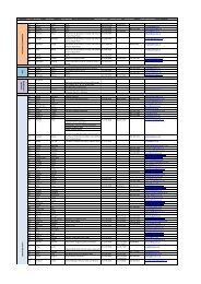
2 Scope split to be confirmed between WSP andthe Operator/DeveloperIndicated WSP scope is provisional and based upon initial assumptions at the time & date of printingof this document.ITEMCONSTRUCTION SCOPEFF&E(WSP)(OPERATOR / DEVELOPER)DATA & VOICE CABLING (CAT6)CAT6 Data & Voice Cabling Copper Fibre Backbone Cabling TELEPHONE CABLING (CAT3)Backbone Cabling ACTIVE NETWORK EQUIPMENTSwitches Servers TV CABLING SYSTEMSatellite Dish TV Point Termination Blocks Head-End Equipment Cabling SECURITY SYSTEMSAccess Control System CCTV Surveillance System VINGCARD SYSTEMVingcard Locks (incl. installation) System Controller FIRE DETECTION SYSTEMDetectors in relevant areas Control Panels and Cabling BUILDING MANAGEMENTSYSTEM (BMS)As Specified WiFi NETWORKEquipment Software & Installation AUDIO VISUAL INSTALLATIONMeeting Rooms Conference Rooms Other J5423-34 Concept Design Report 13
ITEMCONSTRUCTION SCOPEFF&E(WSP)(OPERATOR / DEVELOPER)SERVER ROOMINFRASTRUCTURE43U Data Cabinets Access Flooring Gas Suppression System IN-ROOM ENTERTAINMENT(IPTV – CAT6)TV Set LCD Screens Electronic Set-top Box for TV’s Head-End Equipment Servers Software Licencing PABXPABX System TMS Telephone Handsets POINT OF SALE (POS)Micros Server, Software, Terminals& PrintersServer Installation & Training PROPERTY MANAGEMENTSYSTEM (PMS)Property Management Software Server & Terminal Installation & Training PC’s & SERVERSPC’s with Software File Server Printers 3 ExclusionsThe Electronic Services Cost Estimate excludes for the following for which additional provisionsmust be allowed.3.1 ELECTRICAL3.1.1 Conduits, Cable Trays, Cable Baskets & Wireways25mm Diameter conduits and draw wire, trays and baskets would have to be provided bythe Electrical Contractor.J5423-34 Concept Design Report 14
3.1.2 Site sleeves and manholes infrastructure. As a provisional allowance WSP recommend thefollowing quantities be included in either the Electrical or Civil contractors construction budgets:Data & Electronic Services ONLY:ElectronicServicesData, Fire,Audio,Security and3 rd PartySystemsProposed sleeve and manhole runs for electronic servicesNo. of 110 mm Total Length man hole No. ofSleeves per run (km)size (l x l) Manholes4 8.6 600mm 85Summary Electronic ServicesTotal length of 110mm sleeves used (km) 8.6Total No. of Manholes 853.2 BUILDER'S WORK3.2.1 GeneralOpening through walls and slabs for trays, as required;3.2.2 RisersCable Risers will be required to allow connection of the backbone cabling to all floors fromthe Main ICT Equipment Room.3.3 PROFESSIONAL FEESOur Professional Fees will be based on the ECSA (Engineering Council of South Africa,December 2010) Fee Scale and as agreed with the Quantity Surveyors.Yours faithfullyAdri KotzéPr Techni EngAssociate (Electronic & IT Services)WSP Consulting Engineers SA Pty LtdCarlo CecchiPrincipal AssociateHead of Dept. (Electronic & IT Services)WSP Consulting Engineers SA Pty LtdJ5423-34 Concept Design Report 15