SCP-LC-32-03 (32 V, 3 A) 4-Q current controller for brushed DC ...
SCP-LC-32-03 (32 V, 3 A) 4-Q current controller for brushed DC ...
SCP-LC-32-03 (32 V, 3 A) 4-Q current controller for brushed DC ...
- No tags were found...

You also want an ePaper? Increase the reach of your titles
YUMPU automatically turns print PDFs into web optimized ePapers that Google loves.
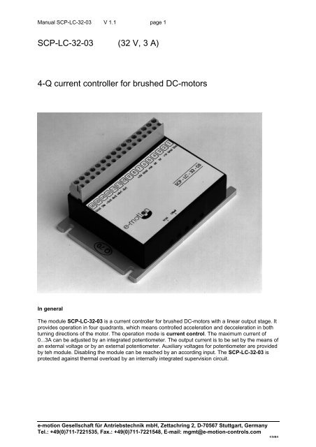
Manual <strong>SCP</strong>-<strong>LC</strong>-<strong>32</strong>-<strong>03</strong> V 1.1 page 1<strong>SCP</strong>-<strong>LC</strong>-<strong>32</strong>-<strong>03</strong> (<strong>32</strong> V, 3 A)4-Q <strong>current</strong> <strong>controller</strong> <strong>for</strong> <strong>brushed</strong> <strong>DC</strong>-motorsIn generalThe module <strong>SCP</strong>-<strong>LC</strong>-<strong>32</strong>-<strong>03</strong> is a <strong>current</strong> <strong>controller</strong> <strong>for</strong> <strong>brushed</strong> <strong>DC</strong>-motors with a linear output stage. Itprovides operation in four quadrants, which means controlled acceleration and decceleration in bothturning directions of the motor. The operation mode is <strong>current</strong> control. The maximum <strong>current</strong> of0...3A can be adjusted by an integrated potentiometer. The output <strong>current</strong> is to be set by the means ofan external voltage or by an external potentiometer. Auxiliary voltages <strong>for</strong> potentiometer are providedby teh module. Disabling the module can be reached by an according input. The <strong>SCP</strong>-<strong>LC</strong>-<strong>32</strong>-<strong>03</strong> isprotected against thermal overload by an internally integrated supervision circuit.e-motion Gesellschaft für Antriebstechnik mbH, Zettachring 2, D-70567 Stuttgart, GermanyTel.: +49(0)711-7221535, Fax.: +49(0)711-7221548, E-mail: mgmt@e-motion-controls.com12/01
Manual <strong>SCP</strong>-<strong>LC</strong>-<strong>32</strong>-<strong>03</strong> V 1.1 page 2specificationelectrical data power supply voltage12- 30 V <strong>DC</strong>Output voltage+/-6V ... +/-24VAdjustable <strong>current</strong> limitation0…3 Ainputs<strong>current</strong> set value 1-10...+10 V<strong>current</strong> set value 1-3...+3 VdisableTTL / CMOS / Schalteroutputsauxiliary voltage source –3 Vauxiliary voltage source +3 Vauxiliary voltage source +5 V 50 mAweight with terminal connector 165 gdimensions (LxWxH) 1<strong>03</strong> x 70 x 39 mmflangeDistance between holes of mounting 96 x 54mmflange (4x screws M3)temperature-range operation0...+45 o Cstorage-40...+80 o Chumidity range non condensing 20% -80% rel. hum.Safety note• operating voltages exceeding the specified values or reverse-connection will destroy the devices.• Unauthorised opening and improper repairs will put the user in danger.• If the module is brought from a cold environment into the operating environment, there can becondensation. Wait until the module has reached the right temperature and is absolutely drybe<strong>for</strong>e it is put into operation.Terminals1 Vcc2 Gnd3 + Vref4 - Vref5 - Motor6 + Motor7 Gnd8 +5V ( max. 50mA )9 nc10 nc11 - Set Value 112 + Set Value 113 - Set Value 214 + Set Value 215 Disable16 Gnde-motion Gesellschaft für Antriebstechnik mbH, Zettachring 2, D-70567 Stuttgart, GermanyTel.: +49(0)711-7221535, Fax.: +49(0)711-7221548, E-mail: mgmt@e-motion-controls.com12/01
Manual <strong>SCP</strong>-<strong>LC</strong>-<strong>32</strong>-<strong>03</strong> V 1.1 page 3Control input <strong>for</strong> disable (Dis)The control input „Dis“ ist <strong>for</strong> disabling the unit and can be controlled as following:• With external switch• Open collector transistor• With TTL/CMOS module„Dis“ not connected or high levelMotor is turning"Dis" connected to Gnd (16) or low levelMotor does not turnEven when the module is diabled a residual <strong>current</strong> of 25mA maximum can occur. This is not a failureof the drive, some small motors without load could drift away.Set value <strong>for</strong> <strong>current</strong>The set value <strong>for</strong> the <strong>current</strong> can be preset like following:a) By the means of an external potentiometer ( Start and End at 3 + 4, wiper at 13 )b) By the means of external voltage -10V .. +10V at 11 + 12c) By the means of external voltage -3V .. +3V at 13 + 14a) Set value with an external potentiometeran external potentiometer with 10kOhm to 47kOhm is required. The potentiometer is to beconnected as following:Start: at „+Vref (3)“End: at „-Vrer (4)“wiper: at „-Sv 2 (13)“b) Set value with external voltage -10V .. +10VThe external set value is connected as following:Set value Gnd to „-Sv1 (11)“Set value at „+Sv1 (12)“c) Set value with external voltage -3V .. +3VThe external set value is connected as following:Set value Gnd to „-Sv2 (13)“Set value at „+Sv2 (14)“Adjusting Offset (Offset)The offset preset by trimming potentiometer „offset“ as follows:Type Maximum left position Maximum right position<strong>SCP</strong>-<strong>LC</strong>-<strong>32</strong>-<strong>03</strong> Offset to ccw-operation Offset to cw-operationAdjusting motor <strong>current</strong> (Imax)The <strong>current</strong> preset by trimming potentiometer „Imax“ as follows:Type Maximum left position Maximum right position<strong>SCP</strong>-<strong>LC</strong>-<strong>32</strong>-<strong>03</strong> 0 A 3AShut down at overheatThe <strong>controller</strong> shuts down automatically when the temperature at the inside of the heat sink exceeds80°C .Assembly notee-motion Gesellschaft für Antriebstechnik mbH, Zettachring 2, D-70567 Stuttgart, GermanyTel.: +49(0)711-7221535, Fax.: +49(0)711-7221548, E-mail: mgmt@e-motion-controls.com12/01
Manual <strong>SCP</strong>-<strong>LC</strong>-<strong>32</strong>-<strong>03</strong> V 1.1 page 4• Optimum heat dissipation is achieved by mounting the module on an cooling surface and by theuse of a thermal conduction paste.Considerations on power supplyOutput voltage :Output <strong>current</strong> :> 12 V and < 30V with a maximumripple of < 5%Regarding mximum motor <strong>current</strong> + <strong>for</strong>accelerationConsiderations to put the device into operation:Please follow the sequence!1. Connect Motor to (5) + (6)2. connect input „disable“ if aplicable.3. preset potentiometers- Potentiometer Offset is adjusted ex works.- Potentiometer Imax is adjusted on a maximum <strong>current</strong> of 3A.4. Connect Set Valuea) external potentiometer 10-47k ( ends at 3 + 4, wiper at 13 ) orb) external voltage-10V .. +10V an 11 + 12 orc) external voltage-3V .. +3V an 13 + 145. connect power supply at 1 + 2 ( !!! check polarity !!! )6. Set <strong>current</strong> set value to 0V and adjust potentiometer Offset until the motor does not turn.7. Adjust maximum <strong>current</strong> by potentiometer Imax.Check this adjustment <strong>for</strong> the whole speed and loadrange.e-motion Gesellschaft für Antriebstechnik mbH, Zettachring 2, D-70567 Stuttgart, GermanyTel.: +49(0)711-7221535, Fax.: +49(0)711-7221548, E-mail: mgmt@e-motion-controls.com12/01