Capacitance and dissipation factor test sets. - Surgetek
Capacitance and dissipation factor test sets. - Surgetek
Capacitance and dissipation factor test sets. - Surgetek

You also want an ePaper? Increase the reach of your titles
YUMPU automatically turns print PDFs into web optimized ePapers that Google loves.
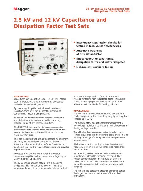
2.5 kV <strong>and</strong> 12 kV <strong>Capacitance</strong> <strong>and</strong>Dissipation Factor Test Sets2.5 kV <strong>and</strong> 12 kV <strong>Capacitance</strong> <strong>and</strong>Dissipation Factor Test Sets■■■■Interference suppression circuits for<strong>test</strong>ing in high-voltage switchyardsAutomatic balancingof <strong>dissipation</strong> <strong>factor</strong>Direct readout of capacitance,<strong>dissipation</strong> <strong>factor</strong> <strong>and</strong> watts dissipatedLightweight, compact designDESCRIPTION<strong>Capacitance</strong> <strong>and</strong> Dissipation Factor (C&DF) Test Sets areused for evaluating the nature <strong>and</strong> quality of electricalinsulation materials <strong>and</strong> systems.By measuring <strong>dissipation</strong> <strong>factor</strong> losses in electricalinsulation, these units can indicate the presence ofcontaminants, fractures <strong>and</strong> punctures.As part of a routine maintenance program, capacitance<strong>and</strong> <strong>dissipation</strong> <strong>factor</strong> <strong>test</strong>ing can aid in predictingpotential failure of deteriorating insulation.The C&DF Test Sets include interference suppressioncircuits that assure accurate measurements even undersevere interference or noise conditions such as thosefound in switchyards.They are the ligh<strong>test</strong> <strong>test</strong> <strong>sets</strong> on the market, making themextremely easy to transport to the <strong>test</strong>ing locations.Automatic balancing of <strong>dissipation</strong> <strong>factor</strong> (power <strong>factor</strong>)significantly reduces the required <strong>test</strong>ing time <strong>and</strong> provideshigher resolution.Two types of C&DF Test Sets are available: one formeasuring <strong>dissipation</strong> <strong>factor</strong> losses at <strong>test</strong> voltages up to2.5 kV; the other up to 12 kV.The 12 kV version consists of two units, a measuringbridge <strong>and</strong> a high-voltage power source. The 2.5 kVversion combines both units in one self-contained <strong>test</strong> set.An extended-range version of the 12 kV <strong>test</strong> set isavailable for <strong>test</strong>ing high-capacitance items. This unit iscapable of <strong>test</strong>ing capacitances of up to 1 µF at 10 kVwhen used with the Biddle Resonating Inductor.APPLICATIONSThe <strong>test</strong> <strong>sets</strong> are used for <strong>test</strong>ing high-voltage electricalinsulation systems at the power frequency by applying <strong>test</strong>voltages up to 12 kV.The purpose of the <strong>dissipation</strong> <strong>factor</strong> measurement ofhigh-voltage insulation is to find early signs of weakness inthe high-voltage insulation.Typical high-voltage equipment <strong>test</strong>ed includes: highvoltagecircuit breakers, transformers, cables <strong>and</strong> potheads,bushings, windings of rotating machines <strong>and</strong> protectivesurge arresters.Dissipation <strong>factor</strong> <strong>test</strong>s on high-voltage insulation arefrequently made in manufacturing facilities, repair shops<strong>and</strong> in the field.By measuring <strong>dissipation</strong> <strong>factor</strong> of the specimen pluscapacitance, undesirable conditions are found. Theyinclude conditions caused by moisture on or in theinsulation; shorts or opens in windings or insulation; <strong>and</strong>conductive contaminants in insulating oil, gas or solidmaterials.The <strong>test</strong> <strong>sets</strong> also detect the presence of internal partialdischarges that occur up to the level of the applied<strong>test</strong> voltage.
2.5 kV <strong>and</strong> 12 kV <strong>Capacitance</strong> <strong>and</strong>Dissipation Factor Test SetsC&DFTestSetCxH BlackCxLRedTwo-winding transformer <strong>test</strong>sCLGThe most important benefit to be gained from a typical<strong>dissipation</strong> <strong>factor</strong> <strong>test</strong> program is obtaining a benchmarkreference reading on costly <strong>and</strong> vital high-voltageapparatus.Whenever possible, these initial readings should be takenwhen the equipment is new <strong>and</strong> when the insulation isclean <strong>and</strong> dry.Later readings taken during the service life of theapparatus can be compared to the benchmark. Increasingvalues of <strong>dissipation</strong> <strong>factor</strong> can represent deterioratinginsulation <strong>and</strong> the need for remedial action.Intervals of one to three years between routine diagnostic<strong>test</strong>s are usually observed for high-voltage transmission<strong>and</strong> distribution apparatus.The <strong>Capacitance</strong> <strong>and</strong> Dissipation Factor (C&DF) Test Setscan perform the following st<strong>and</strong>ard <strong>test</strong>s:Ungrounded Specimen Test (UST)This <strong>test</strong> is made when both specimen terminals can beinsulated from ground. The <strong>test</strong> is often used to reducethe effect of stray capacitance losses to ground <strong>and</strong> toreduce the effect of interference pickup from nearbyenergized apparatus.Typical <strong>test</strong> specimens include the capacitive grading foilsused in high-voltage bushings <strong>and</strong> the interwindinginsulation used in high-voltage transformers.Grounded Specimen Test (GST)HV LeadCHLThis is the most frequently used <strong>test</strong> connection <strong>and</strong>involves all insulation between the high-voltage conductor<strong>and</strong> ground. Typical <strong>test</strong> specimens include transformerwindings to tank <strong>and</strong> core, circuit-breaker assemblies, coilsof rotating machines, etc.HCHGGrounded Specimen Test with Guard Connection(GST-G)This <strong>test</strong> is used to separate the total values of a GST intoseparate parts for better analysis. Often this <strong>test</strong> is usedwith the GST to confirm the <strong>test</strong> readings made using theUST.The C&DF Test Sets can perform excitation-current <strong>test</strong>s ontransformer windings or other insulated coil windings. Amaximum of 400 mA can be used up to 6 kV when <strong>test</strong>inglarge windings.Changes in transformer excitation-current measurementscan indicate internal faults caused by shorted turns in thewindings. This type of measurement has gained wideacceptance in the utility industry.These <strong>test</strong> <strong>sets</strong> make a direct measurement of <strong>test</strong>specimen capacitance, <strong>dissipation</strong> <strong>factor</strong> <strong>and</strong> wattsdissipated. The terms “power <strong>factor</strong>” <strong>and</strong> “<strong>dissipation</strong><strong>factor</strong>” have the same numerical values for the usualoperating range of insulation materials, so generally eitherterm may be used.Some simple conversions may be needed when highervalues (above 10%) are encountered. Because mostnameplate values are given as power <strong>factor</strong> (<strong>dissipation</strong><strong>factor</strong>) by the manufacturer, this <strong>test</strong> set provides quick,easy <strong>and</strong> direct <strong>test</strong> comparisons.FEATURES AND BENEFITS■ Interference suppression circuits allow for accuratemeasurements under severe interference or noiseconditions.■ Automatic balancing of <strong>dissipation</strong> <strong>factor</strong> allows theoperator to perform <strong>test</strong>s quickly <strong>and</strong> with higherresolution.■ Lightweight, compact design makes the <strong>test</strong> <strong>sets</strong>extremely portable. These are the ligh<strong>test</strong> <strong>test</strong> <strong>sets</strong> onthe market.■ Fully shielded <strong>and</strong> guarded circuits eliminate theinfluence of stray capacitances to ground.■ Extended-range <strong>test</strong> set is capable of <strong>test</strong>ing capacitancesof up to 1 µF at 10 kV when used with the ResonatingInductor.
2.5 kV <strong>and</strong> 12 kV <strong>Capacitance</strong> <strong>and</strong>Dissipation Factor Test SetsSPECIFICATIONSInstrumentationCommon to All Test SetsVoltmeter <strong>and</strong> AmmeterDigital readout with LED displayAmmeterAccuracy: ±(1% of reading + 0.1 mA)Resolution: 0.1 mA up to 200 mA; 1 mA above 200 mAAmmeter reads specimen current only.Voltmeter Accuracy: ±(1% of reading + 1 digit)Resolution: 10 VDissipation Factor <strong>and</strong> Watts/Milliwatts0 to 20% DF RangeAccuracy: ±(2% of reading 0.05% DF)Resolution: 0.01% DF0 to 200% DF RangeAccuracy: ±(2% of reading + 0.05% DF)Resolution: 0.1% DFBoth positive <strong>and</strong> negative DF values are indicated automatically.Values up to 1200% DF can be measured by indirect methods.LO/HI equivalent milliwatts/watts dissipated in specimen.<strong>Capacitance</strong>Range0 to 220,000 pF in eight ranges;110/220/1100/2200/11,000/22,000/110,000/220,000 pF full scaleAccuracy±(1% of reading + 2 pF) for ungrounded specimen <strong>test</strong>±(1% of reading + 6 pF)for grounded specimen <strong>test</strong>Resolution: 0.01% of range selectedDecade readout using three dials with eight-range multiplierswitch.Extended-range <strong>test</strong> set capable of <strong>test</strong>ing capacitances of up to1 µF when used with the Resonating Inductor.<strong>Capacitance</strong> Null Detector: Phase-sensitive, zero-center analogmeter with sensitivity selector switch providing six steps of gaincontrol from MIN to MAX. Automatic synchronization of nulldetector to <strong>test</strong> set output current over entire operating rangeTest Selector SwitchUST: Three switch positions. Two or three terminals of specimenare insulated from ground.GST L-GROUND: One switch position. Test specimen has oneinsulated terminal <strong>and</strong> one grounded terminal.GST L-GUARD: Three switch positions. Test specimen has oneinsulated terminal, one grounded terminal <strong>and</strong> one terminal raisedto guard potential.Note: These <strong>test</strong> switch positions are defined in IEEE St<strong>and</strong>ard 62,“Guide for Field Testing Power Apparatus Insulation.”Dimensions (each unit)12.5 H x 19.5 W x 15 D in.(310 H X 510 W x 380 D mm)Weight2.5 kV Unit: 51 lb (23 kg)12 kV Measuring Unit: 48 lb (22 kg)12 kV HV Power Unit: 63 lb (29 kg)Cables Only: 34 lb (15 kg)2.5 kV Test SetInput (specify one)120 V, 60 Hz, 3 A continuous120 V, 50 Hz, 3 A continuous240 V, 60 Hz, 1.5 A continuous240 V, 50 Hz, 1.5 A continuousOutputVoltage: 0 to 2.5 kV ac, digital readoutCurrent: 0 to 100 mA continuousDissipation Factor (or equivalent watts/milliwatts)Automatic, direct readout on digital LED at<strong>test</strong> voltages of 0.25,0.5, 1.0, 1.5, 2.0 <strong>and</strong> 2.5 kV. Indirect at intermediate <strong>test</strong> voltagesInterference SuppressionSeparate capacitance <strong>and</strong> <strong>dissipation</strong> <strong>factor</strong> gain controls withthree-position selector switch (LOW/HIGH/OFF)12 kV Test SetInput (specify one)120 V, 60 Hz, 10 A continuous 120 V, 50 Hz, 10 A continuous240 V, 60 Hz, 5 A continuous 240 V, 50 Hz, 5 A continuousOutputVoltage: 0 to 12 kV ac, digital readoutCurrent: High Range to 5 kV: 0 to 200 mA continuous; 0 to 400mA for 10 minLow Range to 10 kV: 0 to 100 mA continuous; 0 to 200 mA for10 minDissipation Factor (or equivalent watts/milliwatts)Automatic, direct readout on digital LED at <strong>test</strong> voltages of1, 2,2.5, 4, 5, 6, 8, 10 <strong>and</strong> 12 kVInterference SuppressionSeparate capacitance <strong>and</strong> <strong>dissipation</strong> <strong>factor</strong> gain controlswith seven position selector switches (a/b/c/d/e/f/OFF)
2.5 kV <strong>and</strong> 12 kV <strong>Capacitance</strong> <strong>and</strong>Dissipation Factor Test SetsORDERING INFORMATIONItem (Qty)2.5 kV <strong>Capacitance</strong> <strong>and</strong> Dissipation Factor Test SetCat. No.120 Vac, 60 Hz 670025120 Vac, 50 Hz 670025-44240 Vac, 60 Hz 670025-45240 Vac, 50 Hz 670025-4712 kV <strong>Capacitance</strong> <strong>and</strong> Dissipation Factor Test Set120 Vac, 60 Hz 670065120 Vac, 50 Hz 670065-44240 Vac, 60 Hz 670065-45240 Vac, 50 Hz 670065-4712 kV Extended Range <strong>Capacitance</strong> <strong>and</strong> DissipationFactor Test Set120 Vac, 60 Hz 670070120 Vac, 50 Hz 670070-44240 Vac, 60 Hz 670070-45240 Vac, 50 Hz 670070-47Included Accessories2.5 kV Unit - 670025Line cord120 volt input 17032-4240 volt input 17032-2Cable assemblyCxH high voltage, 50 ft (15 m) 30012-1CxL high voltage (red), 50 ft (15 m) 25572-3CxL high voltage (blue), 50 ft (15 m) 25572-4External interlock, 10 ft (3 m) 10229-3Ground, 15 ft (4.5 m) 4702-5Cable carrying bag, canvas 18313Instruction manual12 kV Unit - 670065Cable assemblyAVTM670025JInterconnection, four-conductor 30015Interconnection, eight-conductor 30016External interlock, 10 ft (3 m) 10229-3Ground, 15 ft (4.5 m) 4702-5Line cordItem (Qty)Cat. No.120 volt input 17032-4240 volt input 17032-2Cable assemblyCxH high voltage, 70 ft (15 m) 30012-5CxL high voltage (red), 70 ft (15 m) 25572-1CxL high voltage (blue), 50 ft (15 m) 25572-2Cable carrying bag, canvas 18313Instruction manualAVTM670065JA12 kV Unit - 670070Cable assemblyExternal interlock, 10 ft (3 m) 10229-5Interconnection, five-pin 27978Interconnection, eight-pin 27979Ground, 15 ft (4.5 m) 4702-6Line cord120 volt input 17032-4240 volt input 17032-2Cable assemblyCxH high voltage, 70 ft (21.3 m) 30012-5CxL high voltage (red), 70 ft (21.3 m) 25572-1CxL high voltage (blue), 50 ft (15 m) 25572-2Cable carrying bag, canvas 18313Instruction manualAVTM670065JAOptional AccessoriesAll UnitsHot collar straps [3] 670505Tap connectors [2] 670506Calibration st<strong>and</strong>ard 670500-1Oil <strong>test</strong> cell 670511Foam-padded case for calibration st<strong>and</strong>ard 670635Transit case, <strong>test</strong> set 670626Transit case, cables 218744-112 kV Extended-Range Unit OnlyResonating inductor 670600UKArchcliffe Road DoverCT17 9EN Engl<strong>and</strong>T +44 (0) 1304 502101F +44 (0) 1304 207342UNITED STATES4271 Bronze WayDallas TX75237-1088 USAT 800 723 2861 (USA only)T +1 214 330 3203F +1 214 337 3038OTHER TECHNICAL SALES OFFICESValley Forge USA, Toronto CANADA,Mumbai INDIA, Trappes FRANCE,Sydney AUSTRALIA, Madrid SPAIN<strong>and</strong> the Kingdom of BAHRAIN.Registered to ISO 9001:2000 Reg no. Q 09290Registered to ISO 14001 Reg no. EMS 61597CDF_DS_en_V10www.megger.comMegger is a registered trademark