RealTek RTL8305SB Port 4 Application Note
RealTek RTL8305SB Port 4 Application Note
RealTek RTL8305SB Port 4 Application Note

You also want an ePaper? Increase the reach of your titles
YUMPU automatically turns print PDFs into web optimized ePapers that Google loves.
<strong>RealTek</strong><strong>RTL8305SB</strong> <strong>Port</strong> 4 <strong>Application</strong> <strong>Note</strong>5-port 10/100 Mbps Single Chip Switch Controller<strong>RTL8305SB</strong> <strong>Port</strong> 4 <strong>Application</strong> <strong>Note</strong>1. General DescriptionOperation mode of port4: Each port of <strong>RTL8305SB</strong> has two parts: MAC and PHY. In the UTP and FX mode,<strong>Port</strong>4 uses both the MAC and internal PHY parts like the other ports. In the other mode, <strong>Port</strong>4 uses only theMAC part, which provides an external interface to connect to the external MAC or PHY. Two pins are used forthose operation mode configurations: P4MODE[1:0].The fifth port (port 4) supports an external MAC interface which can be set to PHY mode MII, PHY mode SNI,or MAC mode MII to work with an external MAC of a routing engine, PHY of a HomePNA or other physicallayer transceiver.If the MAC part of <strong>Port</strong>4 connects with an external MAC, such as processor for a router application, it should actas a PHY. This is PHY mode MII or PHY mode SNI. In PHY mode MII or PHY mode SNI, <strong>Port</strong>4 uses the MACpart only, and provides an external MAC interface to connect MAC of external device. In order to connect bothMACs, the MII of the switch MAC should be reversed into PHY mode.If the MAC part of <strong>Port</strong>4 connects with an external PHY, such as a PHY for a HomePNA application, <strong>Port</strong>4 shouldact as MAC. This is MAC mode MII. In MAC mode MII, <strong>Port</strong>4 uses its MAC to connect external PHY and ignoresthe internal PHY part.External MAC interface: In order to act as PHY. When port4 is in PHY mode, some pins of the external MACinterface should be changed. For example, TXC are input pins for MAC but output pins for PHY. So the pinMTXC/PRXC is input for MAC mode and output for PHY mode. Please refer to below diagram to check therelationship between <strong>RTL8305SB</strong> and the external device. Hint: Connect input of <strong>RTL8305SB</strong> to output ofexternal device. <strong>RTL8305SB</strong> has no RXER, TXER, and CRS pins for MII signaling. Because <strong>RTL8305SB</strong> doesnot support pin CRS, it is necessary to connect the MTXEN/PRXDV (output) of PHY mode to both CRS andRXDV (input) of the external device.<strong>Note</strong>: In order to differentiate between MAC and PHY mode, the <strong>RTL8305SB</strong> change the pin name of PHY mode.For example: <strong>RTL8305SB</strong>=MRXD[0]/PTXD[0], RTL8305S=MRXD[0]/MTXD[0].<strong>Port</strong>4 status pins: When P4MODE[1:0]=11, <strong>Port</strong>4 can be either UTP or MAC mode MII. <strong>Port</strong>4 willautomatically detect the link status of UTP from internal PHY and link status MAC mode MII from both TXC ofexternal PHY and P4LNKSTA#. If both UTP and MII port are linked OK, UTP has higher priority and<strong>RTL8305SB</strong> will ignore the signal of MII port.In UTP and FX mode, the internal PHY will provide the port status (Link/Speed/Duplex/Full Flow Controlability) in real time. In order to provide the initial configuration of <strong>Port</strong>4 ’s PHY (UTP or FX mode), four pins(P4ANEG, P4FULL, P4SPD100, P4EEFC) are used to strap upon reset. Upon reset: defined as a short time afterat the end of hardware reset. However, three of these pins are also used for <strong>Port</strong>4’s MAC (the other three modes)in real time after reset (P4SPD100 -> P4SPDSTA, P4FULL -> P4DUPSTA, P4ENFC -> P4FLCTRL). Afterreset: defined as the time after upon reset. <strong>Note</strong>: These 3 pin are changed as high active in order to provide dualfunction. For example: <strong>RTL8305SB</strong>=P4SpdSta/P4Spd100, <strong>RTL8305SB</strong>=P4SpdSta#.In the other three modes, four pins (P4LNKSTA#, P4SPDSTA, P4DUPSTA, P4FLCTRL) are necessary in orderto provides the port status to <strong>Port</strong>4’s MAC in real time. That means that the external MAC or PHY should beforced to the same port status as <strong>Port</strong>4’s MAC. In some applications, xDSL or Home Gateway, CPU or xDSLtransceivers would poll the PHY status via MDC/MDIO interface. <strong>RTL8305SB</strong> provides some specialinformation in MII registers for these applications to satisfy the polling procedure of the master chips. PHY 4register 1.2 reflects the P4LNKSTA# status, and PHY 4 register 0.13 reflects the P4SPDSTA status, and PHY 4register 0.8 reflects the P4DUPSTA status. Other bits in PHY 4 register 0 and 1 would follow the default value ofthe chip definition.<strong>RealTek</strong> Semiconductor Corp. Confidential Page 1 Version 1.0December 20, 2002
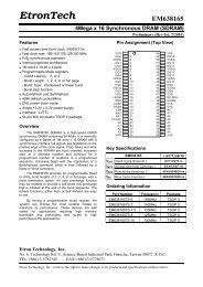
<strong>RealTek</strong><strong>RTL8305SB</strong> <strong>Port</strong> 4 <strong>Application</strong> <strong>Note</strong>5-port 10/100 Mbps Single Chip Switch ControllerRelated pins: When port4 is in UTP or FX mode, the LEDs of port4 are used to displays PHY status. Whenport4 is in other mode, the LEDs of port4 are used to displays MAC status.Four parallel LEDs corresponding to port 4 can be three-stated (disable LED functions) for MII port applicationby setting ENP4LED in EEPROM as 0. In UTP application, this bit should be 1 to drive LEDs of port 4.Pin SEL_MIIMAC# can be used to indicate MII MAC port active after reset for the sake of UTP/MII autodetection.One 25MHz clock output (pin CK25MOUT) can be used as a clock source of the underlying HomePNA/otherPHY physical devices. <strong>Note</strong>: the output voltage is 2.5V for <strong>RTL8305SB</strong> but is 3.3V for RTL8305S.PHY mode MII/PHY mode SNI: In routing application, <strong>RTL8305SB</strong> cooperates with a routing engine tocommunicate with WAN (Wide Area Network) through MII/SNI. In such application, P4LNKSTA# =0 andP4MODE[1] is pulled low upon reset. P4MODE[0] determines whether MII or SNI mode is selected.In MII (nibble) mode (P4MODE[0]=1), P4SPDSTA=1 results in MII operating at 100Mbps with MTXC andMRXC runs at 25MHz; however, P4SPDSTA=0 leads to MII operating at 10Mbps with MTXC and MRXC runsat 2.5MHz.In SNI (serial) mode (P4MODE[0]=0), P4SPDSTA takes no effect and should be pull-down. SNI mode operatesat 10Mbps only, with MTXC and MRXC running at 10MHz. In SNI mode, <strong>RTL8305SB</strong> does not loopbackRXDV signal as response to TXEN and does not support heart-beat function. (asserting COL signal for eachcomplete of TXEN signal).MAC mode MII: In HomePNA or other PHY applications, the <strong>RTL8305SB</strong> provides the MII interface to theunderlying HomePNA or other physical devices so as to communicate with other types of LAN media. In suchapplications, the P4MODE[1:0] pins are floating upon reset and the <strong>RTL8305SB</strong> supports the UTP/MII autodetectionfunction. When both UTP and MII are active (link on), the UTP port has a higher priority over MII port.Floating=HighFloating=High97-P4MODE[1]98-P4MODE[0]59-MRXC/PTXCRXCCRSPull Down=Link On<strong>Note</strong> 1<strong>Note</strong> 2<strong>Note</strong> 3LED Indication49-P4LNKSTA#47-P4SPDSTA/P4FULL48-P4DUPSTA/P4SPD10046-P4FLCTRL/P4ENFC68-SELMIIMAC#/DISDSPRI60-MRXDV/PTXEN67~61-MRXD[3:0]/PTXD[3:0]51-MTXC/PRXC52-MTXEN/PRXDV57~54-MTXD[3:0]/PRXD[3:0]58-MCOL/PCOL44RXDVRXD[3:0]TXCTXENTXDCOLVDSL/HomePNA/Single PHYMAC mode MIIR1<strong>Note</strong> 4<strong>Note</strong> 5Pull DownFloating=HighNot AssemblyR3Pull Down=Link On<strong>Note</strong> 1<strong>Note</strong> 2<strong>Note</strong> 397-P4MODE[1]98-P4MODE[0]72-RESERVED149-P4LNKSTA#47-P4SPDSTA/P4FULL48-P4DUPSTA/P4SPD10046-P4FLCTRL/P4ENFC51-MTXC/PRXC52-MTXEN/PRXDV57~54-MTXD[3:0]/PRXD[3:0]59-MRXC/PTXC60-MRXDV/PTXEN67~61-MRXD[3:0]/PTXD[3:0]58-MCOL/PCOL25MHzU1R244RXCCRSRXDVRXD[3:0]TXCTXENTXDCOLCPU/Processor/Routing EnginePHY mode MII<strong>RealTek</strong> Semiconductor Corp. Confidential Page 2 Version 1.0December 20, 2002
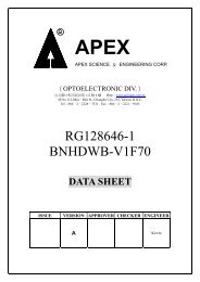
<strong>RealTek</strong><strong>RTL8305SB</strong> <strong>Port</strong> 4 <strong>Application</strong> <strong>Note</strong>5-port 10/100 Mbps Single Chip Switch Controller<strong>Note</strong> 5Pull DownNot AssemblyR3Pull Down=Link On<strong>Note</strong> 1<strong>Note</strong> 2<strong>Note</strong> 397-P4MODE[1]98-P4MODE[0]72-RESERVED149-P4LNKSTA#47-P4SPDSTA/P4FULL48-P4DUPSTA/P4SPD10046-P4FLCTRL/P4ENFC51-MTXC/PRXC52-MTXEN/PRXDV54-MTXD[0]/PRXD[0]59-MRXC/PTXC60-MRXDV/PTXEN61-MRXD[0]/PTXD[0]58-MCOL/PCOL10MHzU1R2R1<strong>Note</strong> 4RXCCRSRXDVRXDTXCTXENTXDCOLCPU/Processor/Routing EnginePHY mode SNI<strong>Note</strong> 1: Pull high or floating means to set the speed as 100Mbps and pull down means to set the speed as10Mbps.<strong>Note</strong> 2: Pull high or floating means to set as full duplex and pull down means to set as half duplex.<strong>Note</strong> 3: Pull high or floating means to enable flow control or backpressure and pull down means to disableflow control or backpressure.<strong>Note</strong> 4: R1 is used to enable/disable the single logic gate, R2 is used to bypass the single logic gate, and U1could be optional selected as 74LVC1G04 or 74LVC1G125 (gate delay within 5 ns) to fine tune thetiming of MII interface trace.<strong>Note</strong> 5: R3 should not be assembled; it’s reserved for future.2. Pin DescriptionThe following table describes the pin definition of the <strong>Port</strong> 4 MII interface.Pin Name Pin No. Type DescriptionP4MODE[1:0] 97,98 I Select <strong>Port</strong> 4 operating mode:11: UTP / MAC mode MII 10: 100Base-FX mode01: PHY mode MII 00: PHY mode SNIThe <strong>RTL8305SB</strong> has 4 options and the RTL8305S has 3options.These pins have internal 75k ohm pull-high resistors.P4LNKSTA# 49 I <strong>Port</strong>4 Link Status for MAC: This pin determines the linkstatus of the <strong>Port</strong>4 MAC in real-time. That is link status of realtimefor MII MAC/MII PHY/SNI PHY only. This pin is lowactive.1: No Link.0: Link.PHY 4, register 1.2 reflects this status in MAC mode MII, andPHY mode MII, and PHY mode SNI.This pin has internal 75k ohm pull-high resistor.P4DUPSTA 48 I <strong>Port</strong>4 MAC Circuit Duplex Status (real time after reset):Duplex Status for MAC circuit (MAC mode MII/PHY modeMII/PHY mode SNI) in real time after reset.1: Full duplex.0: Half duplex.PHY 4, register 0.8 reflects this status in MAC mode MII, andPHY mode MII, and PHY mode SNI.<strong>RealTek</strong> Semiconductor Corp. Confidential Page 3 Version 1.0December 20, 2002
<strong>RealTek</strong>MTXD[3]/PRXD[3]/P4IRTag[1]MTXD[2]/PRXD[2]/P4IRTag[0]MTXD[1]/PRXD[1]/LEDMode[1]575655I/O<strong>RTL8305SB</strong> <strong>Port</strong> 4 <strong>Application</strong> <strong>Note</strong>5-port 10/100 Mbps Single Chip Switch ControllerOutput after reset:For MAC mode MII (P4Mode[1:0]=11), these pins areMTXD[3:0], MII transmit data of MAC.For PHY mode MII (P4Mode[1:0]=01), these pins arePRXD[3:0], MII receive data of PHY.For PHY mode SNI (P4Mode[1:0]=00), PRXD[0] is SNI serialreceive data.These pins have internal 75k ohm pull-high resistors.<strong>Note</strong>: For P4IRTag[1:0] and LEDMode[1:0] please refer to section5.3 of <strong>RTL8305SB</strong>-C datasheet.MTXD[0]/54PRXD[0]/LEDMode[0]MTXEN/PRXDV 52 O For MAC mode MII, this pin represents MTXEN, MII transmitenable.For PHY mode MII, this pin represents PRXDV, MII receiveddata valid.For PHY mode SNI, this pin represents PRXDV, received datavalid.These pins have internal 75k ohm pull-high resistors.MTXC/PRXC 51 I/O For MAC mode MII, it is transmit clock, MTXC (acts as input).For PHY mode MII/PHY mode SNI, it is receive clock, PRXC (actsas output).These pins have internal 75k ohm pull-high resistors.3. MII Register DefinitionFor port 4 MAC application circuit, PHY 4 MII registers real time represent the port 4 MAC part status (linkstatus, speed, duplex; i.e. Reg1.2, Reg.0.13, Reg.0.8). Other register would follow the default value of thechip definition. The detail definition is shown as the following table.3.1 Register0: Control RegisterReg.bit Name Description Mode Default0.15 Reset Reset: 1: PHY reset. This bit is self-clearing. RW/SC 00.14 Loopback(digital loopback)Enable Loopback: This pin enables loopback from the MII TXD to RWthe MII RXD and ignores all the activities on the cable media.01: Enable loopback0: Normal operationThis function is usable only when this PHY is 10Based-T fullduplex or 100Base-T full duplex.The packet is forwarded from other PHY (could be 10Based-T,or 100TX, or 100FX, both full and half duplex) by switch coreand will loopback to the switch core. It could be forwarded tothe other port or dropped depending on the destination andsource MAC address of the packet.0.13 Spd_Sel Speed Select:1: 100Mbps0: 10MbpsWhen Nway is enabled, this bit reflects the result of auto-<strong>RealTek</strong> Semiconductor Corp. Confidential Page 5 Version 1.0December 20, 2002RWFrom pin
<strong>RealTek</strong><strong>RTL8305SB</strong> <strong>Port</strong> 4 <strong>Application</strong> <strong>Note</strong>5-port 10/100 Mbps Single Chip Switch Controller0.12 Auto NegotiationEnablenegotiation. (Read only)When Nway is disabled, this bit can be set through SMI.(Read/Write)When 100FX mode is enabled, this bit =1. (Read only)For MAC mode MII, PHY mode MII, and PHY mode SNI, itreflects the status of P4SPDSTA.1: Enable auto-negotiation processRW0: Disable auto-negotiation processThis bit can be set through SMI.(Read/Write)When 100FX mode is enabled, this bit =0.(Read only)From pin100FX should be force mode. In order to avoid errors, the<strong>RTL8305SB</strong> will ignore the action to this bit when writingReg0.12 as 1 in 100FX mode.0.11 Power Down 1: Power down. All functions will be disabled except SMI RW 0function and internal TXC to MAC.0: Normal operation.0.10 Isolate 1: Electrically isolate the PHY from internal MII. The PHY is RW 0still able to response to MDC/MDIO.0: Normal operation0.9 Restart Auto 1: Restart Auto-Negotiation process.RW/SC 0Negotiation 0: Normal operation.0.8 Duplex Mode Duplex mode:RW From pin1: Full duplex operation0: Half duplex operationWhen Nway is enabled (Reg0.12=1), this bit reflects the resultof auto-negotiation. (Read only)When Nway is disabled (Reg0.12=0, force mode of UTP or100FX), this bit can be set through SMI*. (Read/Write)100FX should be force mode. In order to avoid errors, the<strong>RTL8305SB</strong> will ignore the action to this bit when writingReg0.12 as 1 in 100FX mode.For MAC mode MII, PHY mode MII, and PHY mode SNI, itreflects the status of P4DUPSTA.0.[7:0] Reserved RO 03.2 Register1: Status RegisterReg.bit Name Description Mode Default1.15 100Base_T4 0: No 100Base-T4 capability. RO 01.14 100Base_TX_FD 1: 100Base-TX full duplex capable.RO 10: Not 100Base-TX full duplex capable.1.13 100Base_TX_HD 1: 100Base-TX half duplex capable.RO 10: Not 100Base-TX half duplex capable.1.12 10Base_T_FD 1: 10Base-TX full duplex capable.RO 10: Not 10Base-TX full duplex capable.1.11 10Base_T_HD 1: 10Base-TX half duplex capable.RO 10: Not 10Base-TX half duplex capable.1.[10:7] Reserved RO 01.6 MF PreambleSuppressionThe <strong>RTL8305SB</strong> will accept management frames with ROpreamble suppressed.1The <strong>RTL8305SB</strong> accepts management frames withoutpreamble. Minimum of 32 preamble bits are required for thefirst SMI read/write transaction after reset. One idle bit is<strong>RealTek</strong> Semiconductor Corp. Confidential Page 6 Version 1.0December 20, 2002
<strong>RealTek</strong><strong>RTL8305SB</strong> <strong>Port</strong> 4 <strong>Application</strong> <strong>Note</strong>5-port 10/100 Mbps Single Chip Switch Controller1.5 Auto-negotiateCompleterequired between any two management transactions as definedin IEEE802.3u specs.1: Auto-negotiation process completed. MII Reg.4,5 are valid if RO 0this bit is set.0: Auto-negotiation process not completed.RO/LH 01.4 Remote Fault 1: Remote fault condition detected.0: No remote fault.When in 100FX mode, this bit means in-band signal Far-End-Fault is detected.1.3 Auto-NegotiationAbility1.2 Link Status 1: Link is established. If link had ever failed, this bit will be 0until after reading this bit again.0: Link is failed.1: Nway auto-negotiation capable. (permanently: 1) RO 1RO/LL 0For MAC mode MII, PHY mode MII, and PHY mode SNI, itreflects the status of P4LNKSTA#.1.1 Jabber Detect 0: No Jabber detected.RO 0<strong>Note</strong>: this function is not necessary for single chip.1.0 Extended Capability 1: Extended register capable. (permanently: 1) RO 1<strong>RealTek</strong> Semiconductor Corp. Confidential Page 7 Version 1.0December 20, 2002