
Create successful ePaper yourself
Turn your PDF publications into a flip-book with our unique Google optimized e-Paper software.
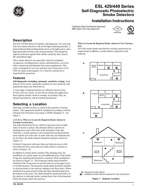
ceiling4”(10cm)NoteMeasurements shown are to theclosest edge of the detector.acceptable herenever heretop of detectoracceptable here4”(10cm)side wall12”(30cm)maximumFigure 3. Plug-in Terminal BlockNoteFor instructions on removal of terminal block andcircuit board, call technical services at 800-648-7424.Figure 2. Detector Placementmountingall boxestest switch4” square orWIREMOLD mounting(No. 5739)Are More Smoke Alarms Desirable?The required number of smoke alarms might not provide reliableearly warning protection for those areas separated by a doorfrom the areas protected by the required smoke alarms. For thisreason, it is recommended that the householder consider the useof additional smoke alarms for those areas for increasedprotection. The additional areas include the basement, bedrooms,dining room, furnace room, utility room, and hallwaysnot protected by the required smoke alarms. The installation ofsmoke alarms in kitchens, attics (finished or unfinished), orgarages is not normally recommended, as these locationsoccasionally experience conditions that can result in improperoperation.Important !Regulations pertaining to smoke detectorinstallations vary from state to state. For moreinformation, contact your local fire departmentor local authority having jurisdiction.In addition to NFPA 72, use the following location guidelines tooptimize performance and reduce the chance of false alarms:• Locate ceiling-mounted smoke detectors in the center of aroom or hallway at least 4 inches (10cm) from any walls orpartitions.• Locate wall-mounted smoke detectors so the top of the alarmis 4 to 12 inches (10 to 30cm) below the ceiling. See Figure 2.• When more than one detector is required, spacing of 30 feet(9m) may be used as a guide on smooth ceilings. Otherspacing may be used depending on ceiling height, high airmovement, and other conditions or response requirements.• Locate in a suitable environment as follows:- Temperature between 32°F (0°C) and 100°F (38°C)- Humidity between 0 and 95% non-condensing• Locate away from air conditioners, heating registers and anyother ventilation source that may interfere with smokeentering the detector.• Locate away from kitchens, wood stoves, garages, furnaces,and bathrooms.• Mount smoke detectors on a firm permanent surface,typically a stud or metal runner.single gang4” octagonmountingcover releaseFigure 4. Detector MountingInstallationThe detectors mount to standard single-gang electrical boxes,four-inch octagonal or four-inch square electrical boxes, or onWIREMOLD No. 5739 fixture boxes. The detectors may also bemounted directly to walls or ceilings where local codes/jurisdictions permit.1. Pull wire through the electrical box and connect to the plug-interminal block supplied, one wire per terminal. See Figures 3and 5.2. Dress wiring neatly and snap the terminal block into the backof the detector.NoteThe detector cover must be closed completely, to supportthe circuit board, while installing the terminalblock.3. Open the cover and mount the detector, using the mountingholes provided. See Figure 4.NotePositive air pressure from wire openings, conduit,mounting boxes, irregular mounting surfaces, orplenums causing air movement through and away fromthe detector may prevent proper operation. Seal allopenings causing unwanted air flow using UL Listedexpanding foam or Duxseal.4. Remove the red plastic dust cover from the detector. Thedetectors are shipped with a dust cover for protection onconstruction sites with dusty environments.2 <strong>ESL</strong> <strong>429</strong>/<strong>449</strong>
<strong>429</strong> <strong>Series</strong> Wiring Diagramfirst detectorModels <strong>429</strong>AT, <strong>429</strong>C,Model <strong>429</strong>CRT last detector<strong>429</strong>CT, <strong>429</strong>CSTauxiliary not used powerpowercontacts- - + +- - + +* Two-Wire CompatibilityRefer to <strong>ESL</strong>’s CompatibilityIndex for compatible controlpanel listings.Compatible ListedControl Unit*fire alarminitiatingcircuit+–End-of-LineDevice<strong>449</strong> <strong>Series</strong> Wiring Diagramfirst detectorModels <strong>449</strong>AT, C, CT, CSTalarmcontactModels <strong>449</strong>CRT, CSRTModels <strong>449</strong>CSRH*local nonlatchingauxiliary alarmsmoke alarm heat sensorpowercontacts contacts powercontacts contacts power- - + +- - + +- - + +last detector* The <strong>449</strong>CSRH unitsare smoke alarms withisolated heat detectors.Listed Control UnitDCpowercircuitfire alarminitiatingcircuit+–redblackbrownPowerSupervisionUnitbrownFigure 5. Wiring DiagramsEnd-of-LineDeviceSupervision of System WiringPower wiring in four-wire systems is required by NFPA 72 to besupervised. This is accomplished by installing a power supervisionrelay at the end of the detector power circuit. The contacts ofthe supervision relay are wired in series with the system’s alarminitiating circuit, and are closed when energized (see Figure 5). Abreak in the detector power circuit or a loss of power de-energizesthe power supervision relay, opening the contacts and causing atrouble annunciation at the fire alarm control unit.<strong>ESL</strong> models 204-6 V and 204-12/24 V are relays UL Listed forfour-wire power supervision. Models <strong>449</strong>CTE and <strong>449</strong>CSTE aresmoke detectors with a built-in end-of-line power supervisonrelay, and can be used to supervise a circuit in place of a powersupervison relay. The <strong>449</strong>CTE and <strong>449</strong>CSTE will also automaticallysend a trouble signal to the control panel whenever thedetector needs maintenance.Installation TestAfter all connections are complete and the wiring is checked forerrors, apply power to the system. There should be no alarm. Ifan alarm is reported, determine if a detector is latched in alarm orif there is a problem with the wiring.Smoke TestThe units should be tested in place annually using one of thefollowing methods:A. Use Smoke! in a can ® and follow the directions on the can.B. Hold a smoldering punk or cotton wick close to the unitand gently direct the smoke into the smoke entry openingsfor 20 seconds or until an alarm is indicated.Be sure to properly extinguish the smoke source aftertesting! This is a go/no go test and is not a reliable indication ofdetector sensitivity. If it is successful, the LED will remain lit.To reset the detector, operate the system reset switch to removepower from the detectors. The control unit alarm and allauxiliary functions should be verified for a complete test of eachdetector.Heat TestModels with heat sensors sample for heat every 3 seconds. Testheat sensors by using a hot air gun. Aim the gun at the heatsensor from 6-10 inches (15-25cm) away. The detector should gointo alarm in less than 30 seconds.<strong>ESL</strong> <strong>429</strong>/<strong>449</strong>3
Sensitivity Test1. Hold the magnet on the hinge side of the unit for more thanone second (see Figure 7). The LED will flash 1 to 9 times.2. Count the number of LED flashes, then use the followingtable to determine if any action is necessary.Flashes0-1 Indication: Unservicable hardware fault.Action: Reset and rerun sensitivity test. If theerror persists, replace unit.2-3 Indication: Unit is becoming insensitive.Action: Clean and reset the unit. Rerunsensitivity test. If the error persists,replace the unit.4-7 Indication: Unit is within normal sensitivity range.Action: N/A8-9 Indication: Unit is becoming too sensitive.Action: Verify the optical chamber is snappeddown securely. Clean the unit andreplace the optical chamber.optical block chamberindentationsnap into indentationLEDSQUEEZE HEREFigure 6. Detector Maintenanceoptical baseAfter the sequence of flashes, if the sensitivity is within limitsand all other tests pass, the unit goes into alarm until reset bythe panel. If the sensitivity is not within limits, or an unserviceablehardware fault is detected, the alarm LED will continue toflash once per second until the unit is reset by the panel.NoteCSRH models auto reset.magnetMaintenanceThe smoke detectors are designed for easy field service andmaintenance. If a detector drifts beyond its approved sensitivityrange for more than 24 hours, or fails internal diagnostic tests, theunit automatically indicates trouble by flashing its LED everysecond. This meets field sensitivity testing requirements withoutthe need for external meters.NoteConnect to a power supply that will not automaticallyreset. Since the self-diagnostics only indicate troubleafter 27 hours, if the power supply automatically resetsevery 24 hours the self-diagnostic indication will neverbe signaled (the smoke detector will still signal alarmcorrectly).In accordance with NFPA 72, smoke detector sensitivity shouldbe checked within one year after installation and every alternateyear thereafter, in commercial installations, or every three years inresidential sites. See Sensitivity Test.The detector’s replaceable optical block chamber unsnaps for easyfield cleaning and service. Whenever the status LED indicatescleaning is necessary, follow these steps:Figure 7. Sensitivity TestingApprovalsThe smoke detectors are for use in commercial fire protectivesignaling systems and in household fire warning systems(NFPA 72).<strong>429</strong>/<strong>449</strong> <strong>Series</strong>Listed by Underwriter’s Laboratories; California State FireMarshal approved (Listed # 7272-0447-128); MEA approved(New York City) (Listed # MEA 64-94-E) Factory Mutualapproved.1. Open the detector cover, unsnap and throw away the opticalblock chamber. See Figure 6.2. Thoroughly blow off the optical base and snap a new opticalblock chamber (part #211) back in place.NoteBe sure the new optical block chamber is seated all theway down.3. Close the detector cover and verify sensitivity. See SensitivityTest.4 <strong>ESL</strong> <strong>429</strong>/<strong>449</strong>
Planning for EmergenciesDevelop a plan to prepare for emergency situations. Discuss andrehearse your plan with everyone by doing a fire drill every fewmonths.WARNINGDo not enter a building where sirens are soundingGuidelines• Understand how to use your fire system.• Know the normal state of doors and windows: open, closed, orlocked.• Escape fast! (Do not stop to pack.)• Use a different escape route if closed doors feel hot to thetouch.• Crawl and hold your breath as much as possible to help reducesmoke inhalation during your escape.• Meet at a designated outdoor location.• Emphasize that no one should return to the premises if there isa fire.• Notify the fire department from a phone in another building.Your Floor PlanWhen establishing your escape routes, consider the followingguidelines:• Have a drawing for each building level.• Show all exits (two exits per room are recommended).• Show the location of stairwells and fire escapes.• Show the location of all components of the fire system.• Show the locations of all fire extinguishers, hoses, ladders, etc.WARNINGSmoke detectors CANNOT provide warnings forfires resulting from explosions, smoking in bed orother furniture, ignition of flammable liquids,vapors and gases, children playing with matches orlighters.Warning! Limitations of SmokeDetectorsSmoke detectors are very reliable, but may not work under allconditions. No smoke detector provides total protection of life orproperty. Smoke detectors are not a substitute for life insurance.Unreliable transmission or receiving of radio frequency(RF) signals may occur if the system is not installed,located, serviced and repaired properly. RF signals sent by thisdetector may be blocked or reflected by metal objects. Adjacentdevices or systems using radio frequency signals may interfere withthe operation of this alarm. Test the system often to be sure thatsignals are being sent and received properly.Smoke detectors may not be heard. A sound sleeper orsomeone who has taken drugs or alcohol may not awaken if thedetector is installed outside a bedroom. Closed or partially closeddoors and distance can block sound. This detector is not designedfor the hearing impaired.Smoke detectors may not always activate and providewarning early enough. Smoke detectors only activate whenenough smoke reaches the detector. If a fire starts in a chimney,wall, roof, on the other side of closed doors, or on a different levelof the property enough smoke may not reach the detector for it toalarm.Limited Warranty<strong>ESL</strong> is a brand of GE Security. The manufacturer warrants thissmoke detector to be free from defects in material and workmanshipunder conditions of normal use for a term of 3 years from thedate of manufacture.During the warranty period, if a GE Security product or any of itscomponents becomes defective, it will be repaired or replacedwithout charge.Out-of-warranty units will be repaired at the discretion of themanufacturer or, if not, a card will be forwarded to the customersuggesting a replacement unit and the cost of that unit.This warranty does not apply to units which have been subject toabuse, misuse, negligence or accident, or to which any modifications,alterations or repairs have been made or attempted.This warranty is extended only to the original purchaser of thesmoke detector and may be enforced only by such person. Duringthe warranty period, if the detector or any warranted componentsthereof becomes defective, it will be replaced or repaired withoutcharge at the manufacturer’s discretion if returned in accordancewith the following instructions:Obtain a Return Authorization Number by calling 1-800-648-7422or 503-692-4052, then carefully pack the detector in a well paddedand insulated carton and return, postal charges prepaid to:Customer Service RMA#GE Security12345 SW Leveton DriveTualatin, OR 97062-9938A note should be included advising the nature of the malfunction.Care must be exercised in the proper packing of detectors returnedunder this warranty as GE Security will not be responsible forwarranty repairs to equipment damaged because of improperpacking.The above warranty is in lieu of all other express warranties,and implied warranties of merchantability and fitnessfor a particular purpose are limited in duration for a periodof THREE years from the date of manufacture. Under nocircumstances shall manufacturer be liable to the purchaseror any other person for incidental or consequentialdamages of any nature, including without limitationdamages for personal injury or damages to property, andhowever occasioned, whether alleged as resulting frombreach of warranty by manufacturer, the negligence ofmanufacturer or otherwise. Manufacturer’s liability willin no event exceed the purchase price of the product. Somestates do not allow limitations on how long an impliedwarranty lasts, or the exclusion or limitation of incidentalor consequential damages, so the above limitations andexclusions may not apply to you. Unless a longer period isrequired by applicable law, any action against manufacturerin connection with this smoke detector must becommenced within one year after the cause of action hasoccurred.No agent, employee or representative of the Manufacturer nor anyother person is authorized to modify this warranty in any respect.Repair or replacement as stated above is the exclusive remedy ofthe purchase hereunder. This warranty gives you specific legalrights and you also have other rights which vary from state tostate.Smoke detectors are a significant help in reducing loss,injury and even death. However, no matter how good adetection device is, nothing works perfectly under everycircumstance and we must warn you that you cannot expecta smoke detector to ensure that you will never suffer anydamage or injury.<strong>ESL</strong> <strong>429</strong>/<strong>449</strong>5
Product Selection Guide<strong>Series</strong>DesignatorModel DesignatorFeatures<strong>449</strong>CSRTWire Type Model Designator Power DesignatorNumber Description Designator Listing Designator Power2 Two-wire only 9 UL A 6/12 VDC4 Four-wire only C 12/24 VDCWire TypePower DesignatorFeaturesDesignator Feature DescriptionE End-of-Line Power Built-in end-of-line relay that also acts as a sensitivity status output. For four-wire only. Fail-safeSupervisory and relay trips upon loss of power or if smoke detector is outside the approved sensitivity range forSensitivity Status more than one day. End-of-line resistor is easily connected to terminal with no extra wiring, orRelayrelay contacts can be connected to a separate trouble loop.H Isolated Fixed Temp. Isolated fixed 135°F (57°C) and rate-of-rise heat detector, independently trips the LED and alarmand Rate-of-Rise relay output. Smoke detector activates internal sounder (local alarm) and auxiliary relay, but doesHeat Detectornot latch. Approved as both single station smoke alarm and system heat detector.R Auxiliary Relay Used to activate other devices such as elevator recall, door holders, etc. UL Listed for releasing services.S Built-in Sounder 85db built-in sounder alarms when smoke is detected or when power wiring polarity is reversed.T Integrated Fixed Temp. Integrated fixed 135°F (57°C) temp. and rate-of-rise heat detector offers double protection.and Rate-of-Rise Either heat detector or smoke detector can trip and latch LED and alarm relay outputs.Heat DetectorElectrical SpecificationsModel 2-Wire 4-Wire Min.Volt. Max.Volt. Max. Ripple Typ.Avg.Stby. Typ. Alarm Cur. Typ.Avg. Pol. Alarm Relay Other Relay(PK to PK) Cur. (12-24V) (12-24V) Rev.Cur. Contacts Contacts(V) (uA) (mA) (mA) (A) (A)<strong>429</strong>AT * 6.5 20 10% 70 *see S09A - - -<strong>429</strong>C * 8.5 33 10% 70 *see S10A - - -<strong>429</strong>CT * 8.5 33 10% 70 *see S10A - - -<strong>429</strong>CRT * 8.5 33 10% 70 *see S11A - - 2<strong>429</strong>CST * 8.5 33 10% 70 *see S11A 10 - -<strong>449</strong>C * 8.5 33 10% 70 15 - 0.5 -<strong>449</strong>CT * 8.5 33 10% 70 15 - 0.5 -<strong>449</strong>CRT * 8.5 33 10% 70 31 - 0.5 -<strong>449</strong>AT * 5.1 27 10% 70 15 - 0.5 -<strong>449</strong>CST * 8.5 33 10% 70 40 10 0.5 -<strong>449</strong>CSRT * 8.5 33 10% 70 51 10 0.5 2<strong>449</strong>CSRH ** * 8.5 33 10% 70 51 10 0.5 2<strong>449</strong>CSTE * 8.5 33 10% 23mA 51 33 0.5 2<strong>449</strong>CTE * 8.5 33 10% 23mA 31 23 0.5 2Power Supervision UnitsModel Min.Volt. Max. Volt. Typ. Avg. Stby.Cur.(uA) Relay Contacts (A)204-6V (UL Listed) 5.1 15 33mA @ 6VDC 0.5204-12/24V (UL Listed) 8.5 33 14mA @ 12VDC, 28mA @ 24VDC 0.5AccessoriesSM-200Smoke! in a can® canned smoke for functional testing of smoke detectorsSM-EXT1 Smoke! in a can® extension accessory211 Replacement optical blocks (set of 10)241 Terminal block for 4-wire smoke detectors <strong>449</strong>CTE, <strong>449</strong>CSTE, <strong>449</strong>AT, <strong>449</strong>C, <strong>449</strong>CT,<strong>449</strong>CST* <strong>429</strong> models draw up to a maximum of 60mA current if not limited by panel.** <strong>449</strong>CSRH model is a smoke alarm with isolated heat detector.Certain items in the installation instructions are protected under one or more of the following patents: 5,546,074; 5,798,701; 5,821,666;6,756,906SpecificationsOperating temperature ................... ...32°F to 100°F (0°C to 38°C)Operating humidity range ....................... 0 to 95% non-condensingSounder specifications ............................................ 85dB at 10 feetField wiring size ............................................................ 14-24 AWGSelf-diagnostic indication .................. typically 27 hours after reset(do not connect power supply that resets every 24 hours)Heat detector .................. fixed temp 135°F, 50 foot (15m) spacingrate-of-rise 15°F/min > 105°F (8°C/min > 41°C)Auxiliary relay contacts ........ 2A @ 28VDC or 120VAC (resistive)Alarm contacts .................................. 500mA @ 36VDC (resistive)Dimensions ................. 6.1” (15.5cm) diameter x 1.9” (4.7cm) deepWeight ..................................................................... 8.8 oz. (0.25kg)Color ....................................................................................... whiteGE Security12345 SW Leveton DriveTualatin, OR 97062503-692-4052USA & Canada: 800-547-2556Tech Support: 800-648-7424www.ge-security.com14153D / September 2004