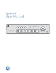
ceiling4”(10cm)NoteMeasurements shown are to theclosest edge of the detector.acceptable herenever heretop of detectoracceptable here4”(10cm)side wall12”(30cm)maximumFigure 3. Plug-in Terminal BlockNoteFor instructions on removal of terminal block andcircuit board, call technical services at 800-648-7424.Figure 2. Detector Placementmountingall boxestest switch4” square orWIREMOLD mounting(No. 5739)Are More Smoke Alarms Desirable?The required number of smoke alarms might not provide reliableearly warning protection for those areas separated by a doorfrom the areas protected by the required smoke alarms. For thisreason, it is recommended that the householder consider the useof additional smoke alarms for those areas for increasedprotection. The additional areas include the basement, bedrooms,dining room, furnace room, utility room, and hallwaysnot protected by the required smoke alarms. The installation ofsmoke alarms in kitchens, attics (finished or unfinished), orgarages is not normally recommended, as these locationsoccasionally experience conditions that can result in improperoperation.Important !Regulations pertaining to smoke detectorinstallations vary from state to state. For moreinformation, contact your local fire departmentor local authority having jurisdiction.In addition to NFPA 72, use the following location guidelines tooptimize performance and reduce the chance of false alarms:• Locate ceiling-mounted smoke detectors in the center of aroom or hallway at least 4 inches (10cm) from any walls orpartitions.• Locate wall-mounted smoke detectors so the top of the alarmis 4 to 12 inches (10 to 30cm) below the ceiling. See Figure 2.• When more than one detector is required, spacing of 30 feet(9m) may be used as a guide on smooth ceilings. Otherspacing may be used depending on ceiling height, high airmovement, and other conditions or response requirements.• Locate in a suitable environment as follows:- Temperature between 32°F (0°C) and 100°F (38°C)- Humidity between 0 and 95% non-condensing• Locate away from air conditioners, heating registers and anyother ventilation source that may interfere with smokeentering the detector.• Locate away from kitchens, wood stoves, garages, furnaces,and bathrooms.• Mount smoke detectors on a firm permanent surface,typically a stud or metal runner.single gang4” octagonmountingcover releaseFigure 4. Detector MountingInstallationThe detectors mount to standard single-gang electrical boxes,four-inch octagonal or four-inch square electrical boxes, or onWIREMOLD No. 5739 fixture boxes. The detectors may also bemounted directly to walls or ceilings where local codes/jurisdictions permit.1. Pull wire through the electrical box and connect to the plug-interminal block supplied, one wire per terminal. See Figures 3and 5.2. Dress wiring neatly and snap the terminal block into the backof the detector.NoteThe detector cover must be closed completely, to supportthe circuit board, while installing the terminalblock.3. Open the cover and mount the detector, using the mountingholes provided. See Figure 4.NotePositive air pressure from wire openings, conduit,mounting boxes, irregular mounting surfaces, orplenums causing air movement through and away fromthe detector may prevent proper operation. Seal allopenings causing unwanted air flow using UL Listedexpanding foam or Duxseal.4. Remove the red plastic dust cover from the detector. Thedetectors are shipped with a dust cover for protection onconstruction sites with dusty environments.2 <strong>ESL</strong> <strong>429</strong>/<strong>449</strong>
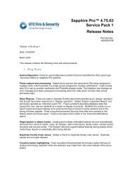
<strong>429</strong> <strong>Series</strong> Wiring Diagramfirst detectorModels <strong>429</strong>AT, <strong>429</strong>C,Model <strong>429</strong>CRT last detector<strong>429</strong>CT, <strong>429</strong>CSTauxiliary not used powerpowercontacts- - + +- - + +* Two-Wire CompatibilityRefer to <strong>ESL</strong>’s CompatibilityIndex for compatible controlpanel listings.Compatible ListedControl Unit*fire alarminitiatingcircuit+–End-of-LineDevice<strong>449</strong> <strong>Series</strong> Wiring Diagramfirst detectorModels <strong>449</strong>AT, C, CT, CSTalarmcontactModels <strong>449</strong>CRT, CSRTModels <strong>449</strong>CSRH*local nonlatchingauxiliary alarmsmoke alarm heat sensorpowercontacts contacts powercontacts contacts power- - + +- - + +- - + +last detector* The <strong>449</strong>CSRH unitsare smoke alarms withisolated heat detectors.Listed Control UnitDCpowercircuitfire alarminitiatingcircuit+–redblackbrownPowerSupervisionUnitbrownFigure 5. Wiring DiagramsEnd-of-LineDeviceSupervision of System WiringPower wiring in four-wire systems is required by NFPA 72 to besupervised. This is accomplished by installing a power supervisionrelay at the end of the detector power circuit. The contacts ofthe supervision relay are wired in series with the system’s alarminitiating circuit, and are closed when energized (see Figure 5). Abreak in the detector power circuit or a loss of power de-energizesthe power supervision relay, opening the contacts and causing atrouble annunciation at the fire alarm control unit.<strong>ESL</strong> models 204-6 V and 204-12/24 V are relays UL Listed forfour-wire power supervision. Models <strong>449</strong>CTE and <strong>449</strong>CSTE aresmoke detectors with a built-in end-of-line power supervisonrelay, and can be used to supervise a circuit in place of a powersupervison relay. The <strong>449</strong>CTE and <strong>449</strong>CSTE will also automaticallysend a trouble signal to the control panel whenever thedetector needs maintenance.Installation TestAfter all connections are complete and the wiring is checked forerrors, apply power to the system. There should be no alarm. Ifan alarm is reported, determine if a detector is latched in alarm orif there is a problem with the wiring.Smoke TestThe units should be tested in place annually using one of thefollowing methods:A. Use Smoke! in a can ® and follow the directions on the can.B. Hold a smoldering punk or cotton wick close to the unitand gently direct the smoke into the smoke entry openingsfor 20 seconds or until an alarm is indicated.Be sure to properly extinguish the smoke source aftertesting! This is a go/no go test and is not a reliable indication ofdetector sensitivity. If it is successful, the LED will remain lit.To reset the detector, operate the system reset switch to removepower from the detectors. The control unit alarm and allauxiliary functions should be verified for a complete test of eachdetector.Heat TestModels with heat sensors sample for heat every 3 seconds. Testheat sensors by using a hot air gun. Aim the gun at the heatsensor from 6-10 inches (15-25cm) away. The detector should gointo alarm in less than 30 seconds.<strong>ESL</strong> <strong>429</strong>/<strong>449</strong>3