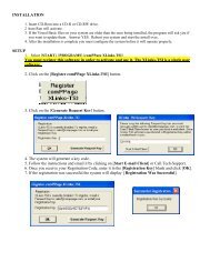
User & Installation Manual RS-232 Radio Paging ... - Comp Page
User & Installation Manual RS-232 Radio Paging ... - Comp Page
User & Installation Manual RS-232 Radio Paging ... - Comp Page

Create successful ePaper yourself
Turn your PDF publications into a flip-book with our unique Google optimized e-Paper software.
II<strong>User</strong> & <strong>Installation</strong> <strong>Manual</strong><strong>RS</strong>-<strong>232</strong> <strong>Radio</strong> <strong>Paging</strong> System
ConneXions II V7 MAC US Multi Port, Mains, USA VersionPREFACEImportant <strong>Installation</strong> InformationIt is the purchasers’ responsibility to determine the suitability of this equipment and its derivatives for any givenapplication, Scope cannot give specific advice in this manual, as each use will require independent evaluation.Scope has, wherever possible, employed extra safeguards or designed optional equipment to further monitor thesystem’s performance. Certain system installations, operational requirements or budgets may, however, limit theeffectiveness of these safeguards. Again, the suitability of the system for any given application must therefore bedecided by the installer and their customer, relative to the application and risk.LicenceThis equipment is cleared for use within the USA under a license assigned to the exclusive importer, PIPSHoldings Inc. License No. 950415906. Certain restrictions apply in respect of power output and antennainstallations.Alternative frequencies are available by formal license application (Form 600) via the FCC. These will not besubject to the same restrictions as the standard assigned license. You should obtain the FCC Rules andRegulations, Title 47, Part 80 to End, including Parts 90 and 95, available from the US Gov. Printing Office, GPOBookstore, FCC Office or www.fcc.gov/oet/info/rules/Important Safety InformationScope products are designed to operate safely when installed and used according to general safety practices.The following requirements should be observed at all times.Do NOT subject this equipment to:Mechanical shockExcessive humidity or moistureExtremes of temperatureCorrosive liquidsThis equipment is designed for indoor use, unless expressly stated otherwise, and must not be used in classifiedHazardous Areas, including areas containing explosive or flammable vapors, unless express authorization hasbeen given in writing by the manufacturer. If in doubt, consult your local product dealer for further information.Do not obstruct any slots or openings in the product. These are provided for ventilation to ensure reliableoperation of the product and to protect it from overheating.Only use a damp cloth for cleaning (not liquid or aerosol based cleaners), and ensure that any power is removedfrom the unit prior to beginning the cleaning operation.Removal of covers from the equipment must only be undertaken by authorized service personnel, who mustensure that power is isolated prior to removal.CONV7MACUS 02/00 Issue 22
ConneXions II V7 MAC US Multi Port, Mains, USA VersionPREFACEEquipment ApplicationsIt is the user’s responsibility to determine the suitability of the Scope products for any given application. Scope,including its subsidiaries and Distributors, cannot provide specific advice within this manual, as each applicationwill require independent evaluation. Common sense dictates that certain applications may require back upsystems to cover in the event of mains or equipment failure. All applications should be thoroughly assessed bythe installer in conjunction with the customer so as to minimize risk. Scope has no control of the use andapplication of the frequencies issued by the FCC. Some equipment that is individually licensed may have agreater degree of protection than other equipment that is operated on a FCC License Assignment basis. Thefollowing information, however, may be of benefit.Equipment Testing.Range tests should be carried out at least once a week on portable radio equipment, more often when criticalcriteria apply. This should involve testing the unit past the limit of its required working range. Good workingpractice dictates that a suitable system installation log, covering both portable and fixed equipment must begenerated, together with a record of the dates when the system has been manually checked and/or serviced,(with the aid of suitable test equipment etc.) enabling the system performance to be compared with the originalinstallation data.The frequency of the tests required will vary between applications. If portable equipment has been dropped or isworn by a person involved in an accident, the unit should be tested again before re-use. It must be stressed thatthe physical range tests are essential and that any construction work or movement of plant or equipment couldalter the signaling capability of the unit. <strong>Radio</strong> equipment, like any other requires servicing from time to time toensure that it is operating to its optimum performance. It is therefore essential that equipment is inspected andtested by authorized service centers at least once a year.LiteratureScope Marketing (Communications UK) Ltd, the manufacturer, in conjunction with it’s distributors operates apolicy of continual improvement, and therefore reserve the right to modify or change any specifications withoutprior notice.While every possible care has been taken in the preparation of this manual, Scope does not accept any liabilityfor technical or typographical errors or omissions contained herein, nor for incidental or consequential damagearising from the use of this material.<strong>Installation</strong><strong>Installation</strong> must only be undertaken by an Approved contractor, who shall ensure that all work is carried out incompliance with the appropriate State and Federal Regulations. For mains powered equipment, a readilyaccessible isolating fuse or socket must be located within 1 meter of the equipment.LiabilityScope does not accept liability for any damage or injury, howsoever caused as the result of misuse of thisequipment. It is the responsibility of the user to ensure that the equipment is operated in the manner for which itwas intended and that it is the correct item of equipment for the required task.CONV7MACUS 02/00 Issue 23
ConneXions II V7 MAC US Multi Port, Mains, USA VersionPREFACEWarrantyThis product is warranted as free from defects of workmanship and materials for a period of one year from theoriginal purchase date. During this time, if there is a defect or malfunction of this product, Scope will, with proofof purchase, repair or replace at its discretion any defective parts, free of charge. This does not include wherethe adjustments, parts and repair are necessary due to circumstances beyond the control of Scope, including butnot limited to fire or other casualty, accident, neglect, abuse, abnormal use or battery leakage damage.There are no other expressed or implied warranties except as stated herein, and those excluded include those ofmerchantability and fitness for a particular purpose. In no event will Scope or any of its agents be liable for direct,indirect, special incidental or consequential damages resulting from any defect in the product, even if advised ofthe possibility of such damages.The warranties and remedies set forth above are exclusive and in lieu of all others, oral or written, expressed orimplied. No Scope distributor, dealer, agent or employee is authorized to make any modification, extension oraddition to this warranty.Some states do not allow limitations on how long an implied warranty may last and some states do not allowexclusions or limitation of incidental or consequential damages.Warning ! No <strong>User</strong> Serviceable PartsAlteration or modification to any part of this equipment, without the prior written consent of the manufacturer, willinvalidate all manufacturer approvals and warranties. No adjustments can be undertaken except by qualifiedand licensed persons as defined by the FCC Rules and Regulations. Operation of altered equipment can resultin fines, imprisonment, and/or confiscation of such equipment.© Scope Marketing (Communications UK) Ltd, 2000 All Rights ReservedCONV7MACUS 02/00 Issue 24
ConneXions II V7 MAC US Multi Port, Mains, USA VersionSystem OverviewThe Scope ConneXions II is a POCSAG data display radio paging system which can be used to transmit bothtext and numeric messages direct to pocket pagers carried by individuals or entire groups. Information is inputby way of three <strong>RS</strong><strong>232</strong> serial ports. The unit can also be used in conjunction with an optional telephone interface,thereby enabling any telephone within the building or complex of buildings to access the paging system. Up to9,999 pagers can be supported on any one system.Base Equipment type & description:Transmitter FCC ID:Transmitting Frequency:Effective Range:Connexions II Multi Port, Mains <strong>Paging</strong> Transmitter with10 Dry ContactsJRNUSASERILINK457.575 or 457.550 MHz*Up to 1 mile with standard antenna!*or as specified on separate configuration sheet!optional external aerials and amplifiers available for greater rangeSection 1: <strong>Installation</strong>The information contained in this Section is intended for use by authorized system installationengineers only. Unqualified personnel should not undertake installation of this equipment under anycircumstances whatsoever.Sitting of the hardwareBefore locating the hardware in any given location, it is important to take into account the range of operation thatyou require to obtain from your system. The standard transmitter can quite easily provide ranges of up to a mileor more and will provide excellent propagation on most industrial sites, covering a considerable area with just aquarter wave antenna (BNC terminated) connected directly to the unit.For coverage of very large sites, or where exceptionally difficult operating conditions exist, it may beadvantageous to install an external antenna. Installing the transmitter on the second or third floor of a buildingwill more often than not boost overall range. However, horizontal range is not always required as much aspropagation through a multi-storey building. Here it may be more useful to use a small external antennamounted outside the building at half the building height. Sometimes range is required more in one direction thanin the other: moving the aerial to one side of the building can provide a bias in the required direction, which mayovercome the range difficulties. (See section: Other Antennas).Important: coaxial feeds over 5 metres must employ low loss 50 ohm coax. We normally do not recommendfeeds of more than 15 metres for standard applications. However, we suggest you contact our technicaldepartment where other considerations may prove this to be impractical.A further consideration is the distance between the transmitter and the source of the data feeding the transmitter.With a standard <strong>RS</strong><strong>232</strong> serial interface, data cables should not exceed 15 metres. These cables should bescreened/shielded and must be kept clear of sources of induced magnetic or electrical noise. In the event thatdistances of over 15 metres are required, additional drivers or amplifiers must be installed at both ends of thedata link.CONV7MACUS 02/00 Issue 25
ConneXions II V7 MAC US Multi Port, Mains, USA VersionSome major points to consider when installing equipment:1 Never install antennas near or adjacent to telephone, public address or data communication lines oroverhead power cables.2 Avoid, where ever possible, running antenna coax alongside other cables.3 Avoid mounting the transmitter in suspended ceiling voids, or in the immediate vicinity of telephoneexchanges or computer equipment.4 Always use proprietary 50 ohm coaxial cable between the antenna and the transmitter. If cable runsexceed 5 metres, always use low loss 50 ohm cable such as RG213, UR67 or equivalent.Coaxial cable intended for TV, Satellite or CCTV installations is normally 75 OHM and therefore totallyunsuitable for any transmitter installation manufactured by Scope.5 Also remember that the performance of the system will be affected by the type of material the unit ismounted on and its surroundings.The following is a list of materials that this transmitter will be adversely affected by if mounted on or ifmounted in close proximity to:a) Foil back wall boardb) Metal mesh or wire reinforced glassc) Metal sheeting, large mirrors or suspended ceilingsd) Lift shaftsAll of the above can reflect radio waves and thereby reduce the capability of the transmitter to perform itsdesired functions.6 The circuit boards within this equipment may be harmed by Electrostatic Discharge (ESD). Installersshould avoid touching the circuitry wherever possible, and should ensure that adequate anti-staticprocedures are adhered to at all times (earth bonding with wrist straps, etc).7 Warning! Never transmit without an aerial attached to the transmitter8 Warning! Carefully check the <strong>Installation</strong> section in this manual covering data pin connections prior toinstallation. Damage caused by incorrect connection is the responsibility of the installer!<strong>Installation</strong>The following procedure must be adhered to when installing the ConneXions paging system. Ensure you havetaken into consideration all of the above information before selecting the location for your transmitter. If in doubt,contact the supplier for further advice.1 Remove the cover from the ConneXions II transmitter unit by slackening the four Pozi headscrews located at the top and bottom of the unit (see Diagram 1).2 Carefully lift off the cover and set aside.3 The transmitter should be fixed to an even wall surface using suitable screws fitted through the holesprovided in the chassis plate. Hold the chassis up to the chosen location and with the aid of a pencilmark the position of the mounting holes.CONV7MACUS 02/00 Issue 26
ConneXions II V7 MAC US Multi Port, Mains, USA VersionWarning: Do not use the chassis plate as a template for drilling the holes into the wall. Hammer drills vibratingthrough the chassis may irreparably damage the quartz crystals on the printed circuit boards.4 Place the ConneXions transmitter over the mounting holes and secure the unit with suitable screws.Check that the chassis plate does not bend and that the screws do not snag or pinch any of the internalcables.5 Connect the antenna to the unit via the BNC connector located at the top of the housing. If the antennais an external antenna, or an antenna which is separate from the transmitter unit itself, ensure that theprevious criteria covered under the section headed Siting of the Hardware, have been strictly adheredto (also see section headed Other Antennas).6 It is important to note that due to the number of interfaces brought out to the 9-way ‘D’ connector, greatcare should be taken to use only the lines which are applicable to your installation. Failure to complywith this instruction will almost certainly DESTROY the unit.In your application the transcoder has been configured for a total of three <strong>RS</strong><strong>232</strong> inputs.PL3 and PL2 SERIAL PORTS (9 way D type plug)PL1 SERIAL PORT (25 way D type plug)PIN SIGNAL DIRECTION1 N/C2 RECEIVE DATA (RX) IN3 TRANSMIT DATA (TX) OUT4 DATA TERMINAL READY (DTR) OUT5 GROUND (GND)6 N/C7 REQUEST TO SEND (RTS) OUT8 CLEAR TO SEND (CTS) IN9 +5V (for Scope peripherals)PIN SIGNAL DIRECTION2 TRANSMIT DATA (TX) OUT3 RECEIVE DATA (RX) IN4 REQUEST TO SEND (RTS) OUT5 CLEAR TO SEND (CTS) IN7 GROUND (GND)19 +5V (for Scope peripherals)20 DATA TERMINAL READY (DTR) OUTAs information passes only from the host equipment to the ConneXions transcoder, you will only need to readthe DTR line which if high shows that power is applied to the Connexions unit. The RTS line will be high at theConnexions port when the transcoder is ready to receive data. The ConneXions RTS line should be connectedto the host CTS line to facilitate correct handshaking. Prior to connecting the data cable(s), thoroughly check thesystem pin connections as shown above.Note: the default comms Baud rate settings are as follows:PL3 = 9600 BaudPL1 and PL2 = 1200 Baud(these are factory set in software and are not hardware adjustable)PL1 DRY CONTACTS (25 way D PLUG)CONV7MACUS 02/00 Issue 27
ConneXions II V7 MAC US Multi Port, Mains, USA VersionPIN DESCRIPTION DEFAULT STATE DEFAULT MESSAGE21 DRY CONTACT NO. 1 NORMALLY OPEN ALARM 19 DRY CONTACT NO. 2 NORMALLY OPEN ALARM 213 DRY CONTACT NO. 3 NORMALLY OPEN ALARM 325 DRY CONTACT NO. 4 NORMALLY OPEN ALARM 412 DRY CONTACT NO. 5 NORMALLY OPEN ALARM 524 DRY CONTACT NO. 6 NORMALLY OPEN ALARM 611 DRY CONTACT NO. 7 NORMALLY OPEN ALARM 723 DRY CONTACT NO. 8 NORMALLY OPEN ALARM 810 DRY CONTACT NO. 9 NORMALLY OPEN ALARM 922 DRY CONTACT NO. 10 NORMALLY OPEN ALARM 10Switching any of the above pins to the Common (Ground) pin 7 will trigger the respective alarm.Note: the pre-programmed messages required for each contact, if different from the default, must be specified attime of ordering.7 If the unit is supplied with a sealed lead acid battery, connect the battery leads to the terminals markedBATT+ and BATT- on the power supply+ (Positive) = Black+White stripe - (Negative) = Black8 Replace the cover and re-tighten the four retaining screws.9 Finally, after checking all connections, insert the mains cable supplied into the IEC type connectorlocated at the base of the unit and plug in to a suitable earthed, switched wall outlet. With mains powerapplied, the red LED on the base of the unit should be lit.10 The system is now ready to accept calls from the host terminal. When a call is transmitted, the greenLED on the base of the unit will light momentarily.<strong>Radio</strong> Transmission Baud RateThis is fixed at the factory to suit the pagers supplied and will normally be set at either 512 or 1200 baud. Pleaserefer to the separate configuration sheet and/or delivery note supplied with your unit.Cable Diagram for 9-PinCommunication Ports9Pin to 25Pin Direct ConnectPin # Pin # <strong>Comp</strong>uter Serial Port to ConneXions 9Pin Port1-N/C 1-N/C 9Pin 25Pin2 3 2 23 2 3 34 6 4 65 5 5 76 4 7 57 8 8 48 79 9CONV7MACUS 02/00 Issue 28
ConneXions II V7 MAC US Multi Port, Mains, USA Version25-Pin D-Shell 9-Pin Connector 25-Pin ConnectorOn ConneXions for <strong>Paging</strong> data input for Dry Contact Input1 – N/C 1 – N/C 12 3 23 2 N/C 34 7 45 8 56 6 67 5 78 – N/C 9 – N/C 8 – N/C9 910 1011 1112 1213 1314 1415 1516 16 N/C17 1718 1819 1920 4 20-n/c21 2122 2223 <strong>232</strong>4 2425 25CONV7MACUS 02/00 Issue 29
ConneXions II V7 MAC US Multi Port, Mains, USA VersionConneXionsCONV7MACUS 02/00 Issue 210
ConneXions II V7 MAC US Multi Port, Mains, USA VersionSystem SpecificationMains Input:Mains Power Consumption:System Operating Voltage:System Power Consumption:110V 60Hz10W max13.8V dcless than *50mA standby, 300mA (transmit)Transmitter:Frequency Range:Channel Spacing:450-470 MHz25 KHzTX Baud Rate: 512 or 1200FCC ID No.JRNUSASERILINKGeneral:Ports:Serial Ports:Data Rate:Port configuration:Protocol:Footprint (mm):PL1,PL2 & PL3300, 600, 1200 (default PL1 & PL2), 2400, 4800 or 9600 (default PL3)8,N,1 (default)Scope (default)"328 (L) x 190 (W) x 75 (D) max*dependent on system configuration"excluding aerialScope’s policy is one of continuous development and specifications are subject to change without noticeCONV7MACUS 02/00 Issue 214
ConneXions II V7 MAC US Multi Port, Mains, USA VersionSection 3: Technical InformationThis section provides a more in depth understanding of how messages are formatted for serialcommunication from a host. It need only be studied by those intending to write their own serialcommunication software.Calling <strong>Page</strong>rs<strong>Page</strong>rs all use 7 digit numeric addresses which enables the system to support thousands of pagerswithout identity clashes. Most pagers will support multiple addresses (sometimes referred to as CAPcodes, RIC’s or identities). This enables the pager not only to respond to its own unique address but alsoto respond to group or global addresses.These real 7 digit numeric codes are often substituted for shorter logical numbers which are easier toremember. Under these conditions the host or speciality program within the transcoder will perform analgorithm on the data string received to convert the simpler logical number back into a real 7 digit numberfor transmission.For improved data recovery without error the real 7 digit pager numbers are always spaced 8 digits apart.To avoid system identity clashes, transcoders are provided with a base number within the range of 1000 to1,999,000. If for example a base address of 0100,000 is applied to a transcoder, the first real pagernumber will 0100,008 followed by 0100,016 and so on.Logical pager numbers are normally used on systems fitted with the telephone interface and those whichare interfaced to personal computers. The algorithm would perform the following function:-For example take the logical pager number of 123The logical pager number 123 will be multiplied by 8 and then added to the base number to provide the 7digit real numberLogical No Base No Real No123 x 8 = 984 + 0100,000 = 0100984<strong>Page</strong>r address 1 is normally reserved as the personal identity for that specific pager. Other addresses, ofwhich there can be 6 or more, can be tagged to specific pagers to form selected groups. Address 2 could,for example, be used for all pagers to formulate a global call.Address codes can be divided between full addresses and sub addresses. Full addresses can allow fourdifferent beep types, A, B, C or D, whereas sub-addresses will only accommodate a fixed beep type. Astatus line of information will normally be provided on the pager screen which will highlight the type ofbeep sent together with other status information.CONV7MACUS 02/00 Issue 215
ConneXions II V7 MAC US Multi Port, Mains, USA VersionNumeric <strong>Page</strong>rsExample serial message string:-N0012300A1234567890The ‘N’ informs the transcoder that this message is destined for a Numeric pager. Any data not precededby this will be ignored.Section 3: Technical InformationNext follows the 7 digit pager identity number. All seven digits must be used.The letter following the identity is the beep type of which there are four valid characters, A, B, C or D.Next follows the message to be transmitted, which can include:0-9, space, -(hyphen), ‘U’ (letter U for ‘U’rgent), [,] open/close square brackets, (open square brackets canalso be used to identify the letter ‘C’ for ‘C’ancel). The final character sent is ‘carriage return’ which is nottransmitted but represents the end of message marker.On sending a message to the unit in the correct format the transcoder will immediately recompose thestring into the POCSAG format and transmit the same at the pre-programmed baud rate. This will beaccompanied by the green LED lighting for the same period to show that data is being transmitted. Thetime taken to transmit the message is dependent upon the pager baud rate. For 512 baud this isapproximately 4 seconds, whilst at 1200 baud the time is approximately 2 seconds. The unit can acceptsequential data at 9600 baud which will be buffered and dealt with as soon as the preceding transmissionhas ended. The RTS line from the transcoder will only go high in the unlikely event that the messagebuffer is full.Alphanumeric <strong>Page</strong>rsExample serial message string:-A0012300A This is a message The data format is exactly as for numeric pagers, except that the recognition character at the front of themessage is changed from an ‘N’ to an ‘A’.Transmission baud rate: in the above example, the default baud rate is sent.To change the transmission baud rate in a message string, placing a letter “N” after the “A” will alter it to512 baud. Placing a letter “F” after the “A” will alter it to 1200 baud.The default setting for the Connexions V7 is 1200 baud.************************************************************************CONV7MACUS 02/00 Issue 216
ConneXions II V7 MAC US Multi Port, Mains, USA VersionIndustry Communications ProtocolsAppendix AThis section deals with the serial data formats commonly used within the On-site <strong>Paging</strong> Industry. Scopehas its own proprietary protocol, but can for certain systems provide a number of other industryrecognizedprotocols. Warning! Check the protocols available for any given unit before quoting for aspecific application. Maximum permissible message lengths will apply. Numeric will always limit to 20digits. Alphanumeric will depend upon the product in question or the software issue employed. Checkbefore quoting or ordering.Scope ProtocolNumeric <strong>Page</strong>rsExample serial message string transmitted from the host to the transceiver:-N0012300A1234567890The ‘N’ informs the transcoder that this message is destined for a Numeric pager. Any data not precededby this will be ignored. The maximum message length within the characters allowed for the Numerictransmission format is 20.Next follows the 7digit pager identity number. All seven digits must be used.The letter following the identity is the beep type of which there are four valid characters, A, B, C or D.Next follows the message to be transmitted, which can include:0-9, space, -(hyphen), ‘U’ (letter U for ‘U’rgent), [,] open/close square brackets, (open square brackets canalso be used to identify the letter ‘C’ for ‘C’ancel). The final character sent is ‘carriage return’ ,which is not transmitted but represents the end of message marker.On sending a message to the unit in the correct format the transcoder will immediately recompose thestring into the POCSAG format and transmit the same at the pre-programmed baud rate. The time takento transmit the message is dependent upon the pager baud rate and the length of the message string.Alphanumeric <strong>Page</strong>rsExample serial message string:-A0012300A This is a message The data format is exactly as for numeric pagers, except that the recognition character at the front of themessage is changed from an ‘N’ to an ‘A’ and the data can include the ISO 646 character set (fullalphabet including both upper and lower case). The maximum message length will be from 512 to 2,000characters depending on the software issue installed.Transmission baud rate: in the above example, the default baud rate is sent.To change the transmission baud rate in a message string, placing a letter “N” after the “A” will alter it to512 baud. Placing a letter “F” after the “A” will alter it to 1200 baud.The default setting for transmission to pagers on Scope transmitters is 1200 baudCONV7MACUS 02/00 Issue 217
ConneXions II V7 MAC US Multi Port, Mains, USA Version<strong>Comp</strong> 2 or People Finder ProtocolAppendix AThe system must be programmed with valid pager types or ranges. The system can be configured asNumeric, Alphanumeric or mixed. In the case of mixed systems the ranges must be defined at the time ofordering within the overall range 1 through 9,999. E.g. this could be ID 1 to 1000 reserved for numeric and1001 to 9,999 for Alphanumeric. Remember that the range selected must allow for Group Calls as well asindividual pager ID’s. The reason for the range requirement is due to the change in the transmitted dataword format under the POCSAG standard, coupled with the fact that the serial data provided by the hostunder this format does not allow the transcoder to differentiate between numeric and alphanumeric dataformats.Example Numeric serial message string transmitted from the host to the transceiver:-1234A1234567890U[-] The data starts with a one to four digit number followed by a beep type, (A,B,C or D) and then a ‘carriagereturn’ . This is then followed by the message (20 digits max) and another ‘carriage return’ .On sending a message to the unit in the correct format the transcoder will immediately recompose thestring into the POCSAG format and transmit the same at the pre-programmed baud rate. The time takento transmit the message is dependent upon the pager baud rate and the length of the message string.Example Alphanumeric serial message string:-1234A This is a message The sequence is exactly the same as for Numeric data except that the information transmitted can includethe ISO 646 character set (full alphabet including both upper and lower case).<strong>Comp</strong> 2 can also provide message prioritization on certain Scope systems equipped with messagebuffering. This utilizes the A,B,C,D beep type to set the level of priority. Certain Scope products will alsoaccept this format without the beep type included in the message string. This will invoke a default beeptype being inserted by the transcoder.<strong>Comp</strong> 1 ProtocolThis is a simplistic interface which accepts a serial data string from the host and adds a single cap ID oraddress to the string enabling it to be transmitted to pagers globally.Example Alphanumeric serial message string:-This is a message On receiving a valid message string the transcoder will immediately add the pre-programmed ID and beeptype, recompose it into the POCSAG format and transmit the same at the pre-programmed baud rate. Thetime taken to transmit the message is dependent upon the pager baud rate and the length of the messagestring.CONV7MACUS 02/00 Issue 218
ConneXions II V7 MAC US Multi Port, Mains, USA VersionTAP - (T)elocator (A)lphanumeric (P)rotocol:Appendix ATAP is commonly used in the wide-area paging industry, generally between remote transmitting stationsvia a modem. Its' advantage lies in the two-way nature of the communications link, and using checksums,the ability to request retransmissions in the event that an error is detected by the receiving station.There are two optional parameters: the password and a sign-off text message, and either or both ofthese can be included.Scope TAP implementation adheres strictly to the Version 1.8 specification, and will allow both of theseparameters to be defined or left out. If a password is not programmed into the system, it will not expectone, the same goes for the sign-off string, if the entry is blank it will not appear.A typical TAP transaction is as follows:1 The caller makes sure the receiving station is connected by requesting a response.2 The receiving station responds with a request for the identity of the caller, in this case the enquiryconsists of the text string 'ID='.3 The caller then sends a string to identify the protocol it intends to use, and a password if this isrequired.4 If the receiving station accepts the response and password it acknowledges the fact and thenrequests the sender deliver the message it is holding for transmission.5 The sender transmits the pager number and text message to deliver, and attaches achecksum based on the contents of the data transmitted. (see example below).6 The receiving station computes the checksum from the received data and if it matches theappended checksum of the received data, acknowledges the fact or requests a re-transmission ofthe data if this is not the case.7 The sending station will then either request another message block is transmitted, or indicateto the remote station that the transaction is complete.8 Once all the data has been sent, and the sending station indicates this fact, the receiving stationwill optionally send a sign-off message, and instruct the sender to terminate the link. If nosign-off message is included, only the link termination command is issued.On a modem-connected link, this would be the point at which the line is dropped by both sides. On apermanent link, the sender and receiving station return to their normal handshake exchanges to verify thelink, or cease communication until another transaction is required.These steps are normally limited to a set number of attempts, due mainly to the requirement that atelephone or modem link should not be maintained indefinitely. For this reason there are also timeconstraints which specify how long to wait for a given response.These 'retry' numbers and time limits are the other 'flexible' options in the TAP protocol. The Scopesystem allows the installer to specify these values for themselves to suit the application to which theprotocol is applied.CONV7MACUS 02/00 Issue 219
ConneXions II V7 MAC US Multi Port, Mains, USA VersionAppendix AExample of typical Command-Acknowledge Sequence:CALLERRECEIVING STATION every 1 second unit…..PG11TEST190(“TEST” is the message)(“190” is the Checksum)ID=[pProcessing-Please Wait+++,,,,,,,,,,ATHOCarrier DropExample Checksum:The following table shows an example of a complete block containing a correct checksum which is :123ABC17;STX *123 *CR *A *B *C *CRETX ****000 *011 *011 *011000 *100100 *100 *000 *000 *1 01111 70010 *00010010 *0011 *1101 *0001 *0010 *0011 *1101 *0011 *1011; *Checksum = 17*********************************************************************CONV7MACUS 02/00 Issue 220
ConneXions II V7 MAC US Multi Port, Mains, USA VersionSerial Cable 9-9Pin ConneXions Issue 7SuppliedSingle or Triple <strong>RS</strong><strong>232</strong> PortsVSP12860VVSP12824VSDCPROGSerial Cable 9-9 Pin<strong>Comp</strong>uter <strong>Paging</strong> usingNetwork or Standalone<strong>Paging</strong> Software10-Voltage Free ContactsAnd <strong>RS</strong><strong>232</strong> Input usingPL1 of a 3-Port Unit.PL1 is a 25-Pin MaleCONV7MACUS 02/00 Issue 221