UNDERSTANDING ASCE-10 COMPRESSION AND TENSION ...
UNDERSTANDING ASCE-10 COMPRESSION AND TENSION ...
UNDERSTANDING ASCE-10 COMPRESSION AND TENSION ...

You also want an ePaper? Increase the reach of your titles
YUMPU automatically turns print PDFs into web optimized ePapers that Google loves.
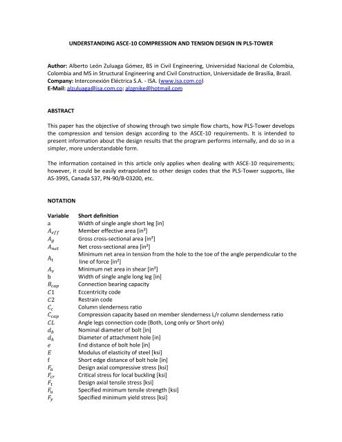
<strong>UNDERST<strong>AND</strong>ING</strong> <strong>ASCE</strong>-<strong>10</strong> <strong>COMPRESSION</strong> <strong>AND</strong> <strong>TENSION</strong> DESIGN IN PLS-TOWERAuthor: Alberto León Zuluaga Gómez, BS in Civil Engineering, Universidad Nacional de Colombia,Colombia and MS in Structural Engineering and Civil Construction, Universidade de Brasília, Brazil.Company: Interconexión Eléctrica S.A. - ISA. (www.isa.com.co)E-Mail: alzuluaga@isa.com.co; alzgnike@hotmail.comABSTRACTThis paper has the objective of showing through two simple flow charts, how PLS-Tower developsthe compression and tension design according to the <strong>ASCE</strong>-<strong>10</strong> requirements. It is intended topresent information about the design results that the program performs internally, and do so in asimpler, more understandable form.The information contained in this article only applies when dealing with <strong>ASCE</strong>-<strong>10</strong> requirements;however, it could be easily extrapolated to other design codes that the PLS-Tower supports, likeAS-3995, Canada S37, PN-90/B-03200, etc.NOTATIONVariableShort definitionWidth of single angle short leg [in]Member effective area [in²]Gross cross-sectional area [in²]Net cross-sectional area [in²]Minimum net area in tension from the hole to the toe of the angle perpendicular to theline of force [in²]Minimum net area in shear [in²]Width of single angle long leg [in]Connection bearing capacityEccentricity codeRestrain codeColumn slenderness ratioCompression capacity based on member slenderness L/r column slenderness ratioAngle legs connection code (Both, Long only or Short only)Nominal diameter of bolt [in]Diameter of attachment hole [in]End distance of bolt hole [in]Modulus of elasticity of steel [ksi]Short edge distance of bolt hole [in]Design axial compressive stress [ksi]Critical stress for local buckling [ksi]Design axial tensile stress [ksi]Specified minimum tensile strength [ksi]Specified minimum yield stress [ksi]
VariableShort definitionEffective length factorUnbraced length of member [in]Unbraced member length about its local x-axisUnbraced member length about it local y-axisUnbraced member length about it local z-axisNumber of angles in cross sectionNumber of bolts in end connectionNumber of bearing areas per boltNumber of holes to be deductedNumber of shear planes per boltTension capacity based on net sectionMember radii of gyration [in]Connection block shear capacityConnection rupture capacityConnection end, edge or spacing distance capacityAlternate unbraced length ratio for crossing diagonalsMember unbraced length ratio for its local x-axisMember unbraced length ratio for its local y-axisMember unbraced length ratio for its local z-axisMember radii of gyration for its local x-axisMember radii of gyration for its local y-axisMember radii of gyration for its local z-axisBolt spacing [in]Connection shear capacityThickness of element [in]Design shear capacity of one bolt [ksi]Flat-width of element [in]Width to thickness ratioUnit factor (1.0 for in ksi)Absolute value of the tension force in the supporting member divided by the force inthe compressed memberDISCLAIMERThe author will be not responsible for any information contained in this article. The conclusionsand recommendations should be used by an experienced engineer, and Licensee assumes allresponsibility for the design assumptions and results.
CAPACITY IN<strong>COMPRESSION</strong>Compression capacity based onmember slenderness L/r, CCAPConnection shear capacity, SCAPConnection bearing capacity, BCAPCrossing diagonals Other members(number of angles in cross section) if= 1 or 2, or/ 2 if = 4Leg membersMembers with a concentricload at both ends (C1=1):Short members: Long members:Members with a concentric load at one endand normal framing at the other end (C1=2):Members with normal framingeccentricities at both ends (C1=3):Other membersInelastic buckling: Elastic buckling:Members unrestrained againstrotation at both ends (C2=4):Members partially restrained againstrotation at one end (C2=5):Members partially restrained againstrotation at both ends (C2=6):Figure 1. Compression design flow chart
CAPACITY IN <strong>TENSION</strong>Members connected byboth legs, (CL=Both):Tension capacity based on net section, Connection shear capacity, Connection bearing capacity, Connection rupture capacity,Members connected bylong leg, (CL=Long Only):Members connected by short leg,(CL=Short Only): (number of angles in cross section) if= 1 or 2, or/ 2 if = 4Figure 2. Tension design flow chart
REFERENCES(1) TOWER – Version 12.3 Manual. Power Line System, Inc ©. 2012.(2) <strong>ASCE</strong> <strong>10</strong> (1997). Design of Latticed Steel Transmission Structures. American Society of CivilEngineers. Reston, Va.