PIR Outdoor Detector Rivelatore da Esterno ad ... - COP Security
PIR Outdoor Detector Rivelatore da Esterno ad ... - COP Security
PIR Outdoor Detector Rivelatore da Esterno ad ... - COP Security
You also want an ePaper? Increase the reach of your titles
YUMPU automatically turns print PDFs into web optimized ePapers that Google loves.
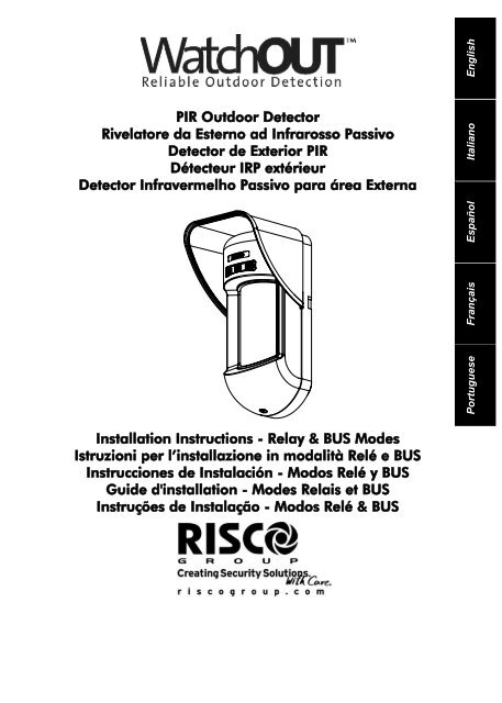
<strong>PIR</strong> <strong>Outdoor</strong> <strong>Detector</strong><strong>Rivelatore</strong> <strong>da</strong> <strong>Esterno</strong> <strong>ad</strong> Infrarosso Passivo<strong>Detector</strong> de Exterior <strong>PIR</strong>Détecteur IRP extérieur<strong>Detector</strong> Infravermelho Passivo para área ExternaPortuguese Français Español Italiano EnglishInstallation Instructions - Relay & BUS ModesIstruzioni per l’installazione in mo<strong>da</strong>lità Relé e BUSInstrucciones de Instalación - Modos Relé y BUSGuide d'installation - Modes Relais et BUSInstruções de Instalação - Modos Relé & BUS
TABLE OF CONTENTSRelay Mode Installation ....................................................................................................... 4Introduction .......................................................................................................................... 4Mounting............................................................................................................................... 4Mounting Considerations................................................................................................ 4Wall Mount Installation ................................................................................................... 6Flat Mounting:................................................................................................................. 645° angle Mounting (Left side mounting)........................................................................ 6Changing Back Tamper position .................................................................................... 7Terminal Wiring ................................................................................................................... 7DIP Switch Settings............................................................................................................... 8Walk test......................................................................................................................... 8LEDs Display ......................................................................................................................... 8Relay Mode / Bus Mode Jumper ........................................................................................ 8Stan<strong>da</strong>rd Swivel Installation ............................................................................................... 9Wall Mounting................................................................................................................. 9Swivel Conduit Mounting ............................................................................................... 9Replacing Lenses................................................................................................................ 11Lens Types ................................................................................................................... 12Technical Specification ...................................................................................................... 13Ordering Information........................................................................................................ 13Accessories Kits .................................................................................................................. 13Camera Option .................................................................................................................. 13BUS Mode Installation ....................................................................................................... 14Introduction ........................................................................................................................ 14Terminal Wiring ................................................................................................................. 14Cover and Back Tamper............................................................................................... 14Cover Tamper Only ...................................................................................................... 14Cover Tamper to Zone Input ........................................................................................ 14DIP Switch Settings............................................................................................................. 14ProSYS Programming ........................................................................................................ 15EnglishWatchOUT <strong>PIR</strong> Installation Manual 3
Relay Mode InstallationIntroductionRISCO Group's <strong>PIR</strong> <strong>Outdoor</strong> detector, WatchOUT, is a unique detector with signal processingbased on two Passive Infrared (<strong>PIR</strong>) correlated channels. The detector can operate as a regularrelay detector connected to any control panel, or as a BUS accessory when connected to RISCOGroup's ProSYS control panel via the RS485 BUS, thus having unique remote control anddiagnostic capabilities.The following instructions describe the installation of the WatchOUT in Relay & BUS mode.MountingMounting Considerations1m - 2.7m(3'3" - 8'9")Optional Height: 1m – 2.7m(3'3"-8'9")Typical Height: 2.2m (7'2")Default Lens: Wide angle 12m (40') 90°(RL300)If possible, avoid pointing the detector tomoving objects (swaying trees, bushesetc.)Note:1. For low installations, below 1.7m (5'6") in whichpet immunity is required, use the suppliedRL300F lens (Low wall or fence installations).2. The detector's pet immunity (height of an animal,no weight limitation), is up to 70 cm (2'4"), wheninstalling the detector at 2.2m (7'2"). If theinstallation is bellow the height mentione<strong>da</strong>bove, the Pet Immunity decreases accordingly;every 10 cm (4") decrease in installation heightle<strong>ad</strong>s to 10 cm (4") decrease in pet imunity.With moving objectskeep distance ofminimum 5 meters (16')For installations with extensive vehicle traffic or targetsbeyond the required detection range, it is recommended totilt the detector down.Note:Tilting the detector down may reduce the pet immunityFor optimum detection, select a locationthat is likely to intercept an intruder movingacross the coverage pattern at a 45°trajectory.5m (16')Out ofDetection RangeEnsure any objects do not obstruct thefield of view. Pay attention to growing treesor bushes, plants with big moving leavesetc.4 WatchOUT <strong>PIR</strong> Installation Manual
Installing WatchOUT <strong>PIR</strong> in challenging situationsIn the following situations rapid and significant infrared r<strong>ad</strong>iation changes can happen in both<strong>PIR</strong> channels together, resulting in false alarms and therefore care should be taken1. Situations in which metal and/or glass objects measuring over 70cm (2’4”) in height fromthe ground are in the field of view of the detector (cars, metal gates, shutters, metal walls,windows, etc.)2. Situations in which a reflective surface on the ground larger than 1m (3’4”) in diameter maycause reflection into the detector’s lens. Examples of a reflective surface on the ground area puddle, wet ro<strong>ad</strong> or car park, smooth concrete or asphalt surface, swimming pool, etc.EnglishTo avoid false alarms in the above situations:1. Reduce the detection range to 1m less than the distance of the metal/glass object orpossible ground surface reflection, as follows.2. Install the WatchOUT <strong>PIR</strong> on the supplied stan<strong>da</strong>rd swivel bracket.3. Reduce the detection range by sliding up the WatchOUT PCB within the detector housing,and by tilting the detector down on the swivel bracket.4. To reduce the required tilting angle, it is recommended to install the detector at a lowermounting height and to use the Pet immune lens for low installations.5. Confirm by walk-test that the WatchOUT <strong>PIR</strong> detects in Area 1, and that no detectionoccurs when walking in Area 2.NOTES:1. Please note that any outdoor <strong>PIR</strong> detector will require reduction in range to a shorter distance than the car,metal object or surface reflection (so that these objects won’t be protected) in order to eliminate falsealarms.2. For full 15m (50’) coverage in the above situations, it is highly recommended to install theWatchOUT DT, the only outdoor detector with 2 <strong>PIR</strong> channels and 2 Microwave channels.3. WatchOUT detectors include high quality Silicon filters on the <strong>PIR</strong> sensors for blocking out white lightinterferences. These filters are not intended to block infrared thermal r<strong>ad</strong>iation.WatchOUT <strong>PIR</strong> Installation Manual 5
Wall Mount InstallationNote:The installation knockouts numbering are marked onthe back plate.Figure 1Figure 2I11. Open WatchOUT front cover (unlock C1,Figure 1).2. Release internal base (unlock I1,Figure 2).3. Select mounting installation as follows:Flat Mounting:Open knockouts on external base (Figure 3).• B1 - B4: Wall mounting knockouts• T1: Back tamper knockout• W2 / W3: wires entry knockouts45° angle Mounting (Left sidemounting)a. Open knockouts on external base(Figure 3)• L1, L2: Left mounting knockouts• T3: Left tamper knockout• W5 / W6: Wire entry knockoutsb. Remove tamper springc. Replace tamper bracket (Item 1) withsupplied flat tamper bracket (Item 2).Item 1 Item 2Figure 3TamperLeverBAC1T1T3L1B1W5W6W3T6T5T4T2R1(not visible)B2W9W2d. Insert Tamper lever B onto T5 and T3and secure screw A (Figure 3)4. Insert external wires through external baseW2, W3 (Flat Mounting) or W5, W6 (Leftside mounting)(Figure 3).5. Secure external base to the wall.Figure 4L2B4R2(not visible)B36. Insert external wires and tamper wiresthrough internal base (Figure 4).7. Secure internal base to external base (lockI1, Figure 2).8. Close the front cover (Lock C1, Figure 1)after wiring and setting DIP switches.9. Walk test the detector.Note:For 45° right side installation use the equivalent units on the external base as follows:Knockouts Description Left RightMounting Knockouts L1, L2 R1, R2Tamper spring knockouts T1,T3 T2,T4Tamper screw anchor T5 T6Wiring Knockouts W5, W6 W7, W86 WatchOUT <strong>PIR</strong> Installation Manual
Changing Back Tamper positionThe back tamper is by default secured on theright side of the internal base (Rear view). Ifyou wish to move it to the left side (rear view),do the following (Figure 5):1. Remove tamper screw 1 in order torelease the tamper from position 7.2. Ensure tamper spring 2 rests over tamperwire base 4.3. Ensure plastic tamper bracket 3 rests overboth 2 and 4.4. Secure tamper screw 1 into 3 overposition 6.Figure 5123Left SideTamper64Right SideTamper75EnglishNotes:a. Verify that you hear a "Click" when attaching the tamper spring to the wall.b. For pole installation, the tamper can be moved to the bottom right-hand side of the internal base.Terminal Wiring12VDC+ -LEDYEL GRN ALARM TAMPER FREE FREE N.O COM N.CENABLN.CN.CWatchOUT <strong>PIR</strong> - PCB+,- 12 VDCYELLOW N/A (Used only for BUS mode installation)GREEN N/A (Used only for BUS mode installation)ALARM N.C relay, 24VDC , 0.1ATAMPER N.C relay, 24VDC , 0.1AFREE A free terminal that can be used to connect wires and EOL resistorsLEDENABLEN.OCOMN.CUsed to remotely control the LEDs when DIP1 is set to ON (used in high securityenvironments).LED Enable: input is +12V OR no terminal connection.LED Disable: Connect the input to 0V.Programmable auxiliary relay terminals. This relay is used to activate auxiliaryunits such as cameras or lighting when an alarm is triggered.The operation of the auxiliary relay depends on the settings of DIP switches 4-7.NORMALALARMN.O COM N.CN.OCOMN.CWatchOUT <strong>PIR</strong> Installation Manual 7
DIP Switch SettingsON1 2 3 4 5 6 7 8FactoryDefaultDIP 1: LEDs operationOn: LEDs enabledOff: LEDs disabledDIP 2-3: <strong>PIR</strong> Detection SensitivitySensitivity DIP2 DIP3Low Off OffMid Off OnNormal On OffMaximum On OnDIP 4: Auxiliary relay controlON: EnabledOFF: DisabledWalk testDIP 5: Used to define the auxiliary relay operationfollowing an alarm condition, depending onDay/Night time (defined by 24 Hours / NightPhotocell)ON (Night): Auxiliary relay is activated onlyduring nighttime.OFF (24 Hours): Auxiliary relay is activated24 hourDIP 6-7: Defines the time duration that the auxiliaryrelay is activatedActivation Time Switch 6 Switch 72.2 seconds OFF OFF2.0 Minutes OFF ON4.0 Minutes ON OFF8.0 Minutes ON ONDIP 8: Red LED /3 LEDON: Red LED onlyOFF: 3 LEDsTwo minutes after applying power, walk test the protected area to verifyproper operation.For installations on uneven surfaces slide the PCB inside the internal base tothe appropriate setting according to the desired height (1.0m, 1.5m, 2.2m,2.7m) as printed on the bottom left corner of the PCB or use the stan<strong>da</strong>rdswivel accessory.For reducing the detection range, slide the PCB up or tilt the swivel down.LEDs DisplayLED State DescriptionYELLOW Ste<strong>ad</strong>y Indicates channel 1 <strong>PIR</strong> detectionSte<strong>ad</strong>y Indicates channel 2 <strong>PIR</strong> detectionGREEN Ste<strong>ad</strong>y Indicates ALARM (Simultaneous 2 <strong>PIR</strong> channels)RED Ste<strong>ad</strong>y Indicates ALARM (Simultaneous 2 <strong>PIR</strong> channels)Flashing Indicates malfunctioned communication with ProSYS (BUS modeonly)All LEDs Flashing(One afteranother)Unit initialization on power upNotes:1. DIP-Switch 1 should be in ON position to enable LED indications.2. Only one LED is active at any one time. For example, in the case of both <strong>PIR</strong> channels detection, either theste<strong>ad</strong>y yellow LED or the ste<strong>ad</strong>y green LED is displayed (the first to detect), followed by the alarm red LED.Relay Mode / Bus Mode JumperJ-BUS jumper (located on the PCB between the red and green LEDs)is used to define the detector’s mode of operation as follows:RelayModeBUSMode1.00M1.55M2.20M2.70MPC8 WatchOUT <strong>PIR</strong> Installation Manual
Stan<strong>da</strong>rd Swivel InstallationThe <strong>Outdoor</strong> detector packaging contains a stan<strong>da</strong>rd swivel for flexible installation. Please followthe instructions below for mounting the detector with the Stan<strong>da</strong>rd Swivel:1. Open WatchOUT front cover (Unlock C1, Figure 1).2. Release internal base (Unlock I1, Figure 2).3. Open knockouts on external base (Figure 6, Detail B)• W1: Wires knockout• S1,S2: Knockouts for securing external base to Stan<strong>da</strong>rd Swivel• S3: External base locking screw knockout4. On the swivel accessory remove the required swivel cable wiring knockout S2, S7 or S9(Figure 6, Detail A).5. Remove back tamper from the internal base (see “Changing Back Tamper Position"paragraph) and connect it to S5 (Figure 6, Detail A) on the Stan<strong>da</strong>rd Swivel.6. Select the mounting installation as follows:Note:Ensure that you see the engraved UP mark on the upper front face of the swivel.Wall Mountinga. Insert external cable wiring through knockouts S2, S7 or S9 and extract them (including thetamper wires) through the Swivel Wires Passage (Figure 6, Detail B).b. Secure swivel to the wall through holes S1, S3, S6 and S8.Swivel Conduit Mounting (using Conduit Metal Swivel A<strong>da</strong>ptor - CSMA, Figure 6, Detail A)CSMADetail AØ 16 mmStan<strong>da</strong>rd SwivelS1 S2 S3W1Detail BSnapsEnglishTamperSpringHolesM1M2M3M4Ø 21 mmS9S8Swivel WiresPassageS7S6S4S1S5Tamper(see Detail C)S2S3Detail CFigure 6Note:The CSMA is required when wiring is in a pipe external to the wall. It should be ordered separately P/NRA300SC0000A.a. Choose the direction upon which to mount the CSMA according to the required diameter:16mm (0.63 inches) or 21mm (0.83 inches).b. Insert conduit to the CSMA.c. Secure CSMA to the wall through points (M1, M4).d. Insert external cables and tamper wires from the conduit through the swivel wires passageof the swivel (Figure 6, Detail A).e. Secure swivel to the wall through holes S1, S3, S6 and S8.Note:The Tamper spring S5 (Figure 6) should make contact with the wall through the tamper spring holes M2 orM3 on the CSMA. Make sure to hear the tamper "Click" when connecting to the wall.WatchOUT <strong>PIR</strong> Installation Manual 9
7. Insert tamper wires and external cable wiring from Stan<strong>da</strong>rd Swivel through knockout W1 onthe external base (Figure 6, Detail B).8. Connect the external base to the swivel using the dedicated snaps (Figure 7).See Detail AExternal BaseSnapsSwivel to External BaseConnecting ScrewsW1S1Internal BaseS2S3Detail AAngle LockingScrew(See Note 2)PCBSwivel AssyConnecting Screw(See Note)Figure 7NOTE:Do not open or close the Swivel Assy Screw since it is used for connecting the swivel parts only.9. Secure external base to swivel with two screws fastened to knockouts S1 and S2 (Figure 7).10. Insert the supplied angle locking screw from the external base through the angle locking screwknockout S3 on the external base to the stan<strong>da</strong>rd swivel (Figure 7).11. Tilt and Rotate the Stan<strong>da</strong>rd Swivel to the desired position.Once the Stan<strong>da</strong>rd Swivel is in the desired position, securethe angle locking screw.12. Line up the internal base onto the external base. Insert allwiring cables through the internal base.13. Secure internal base to external base (Lock I1, Figure 2).14. To re<strong>ad</strong>just the Stan<strong>da</strong>rd Swivel when the PCB is installed(Figure 8):a. Bend down the black foam located below the RED LEDon the PCB (enough to reach the Swivel locking screw).b. Use a Philips screwdriver to release the locking screw(see Figure 8).c. Tilt and/or Rotate the Stan<strong>da</strong>rd Swivel to the desiredposition.d. Secure the angle locking screw.Figure 8NOTE:When marks on the two movable parts are aligned (Figure 7), the Stan<strong>da</strong>rd Swivel is in 0° vertical /horizontalposition. Each click from this position represents shifting of 5° in vertical / horizontal position.15. Close the front cover (Lock C1, Figure 1) and walk test the detector.NOTE:The screw has to pass through External Base and locked to the swivel.10 WatchOUT <strong>PIR</strong> Installation Manual
Replacing Lenses1. Unlock the six screws that hold the lens holding sleeve from the back of the front cover.2. To release the protective sleeve, gently push the lens from the external side of the front cover.3. Disconnect the lens from the sleeve by gently pushing the lens clips that secure it to thesleeve.4. Replace the lens. Place the 4 clips of the lens into the matching holes on the sleeve.5. Insert the protective sleeve back into place on the front cover. Pay attention to place thesleeve over the sealing rubber.6. Secure the 6 holding screws back to their place.Sleeve LockingScrewsLens LockingClipsEnglishLens ProtectingSleeveSealing RubberHoles forLens ClipsFront CoverLocking ScrewWatchOUT <strong>PIR</strong> Installation Manual 11
Lens TypesWide angle lens (RL300) /Low installation - Pet lens(RL300F) :Top view40302010010203011975310135791140 0 2 4 6 8 10 12 14 15090°10 20 30 40 50TypicalInstallationHeight:2.2m (7'2")TypicalInstallationHeight:1.5m (5'3")Wide angle lens (RL300):Side ViewFeet10 310 0Meters 0 2 4 6 8 10 12Feet0 10 20 30 40Low installation - Pet lens (RL300F) :Side viewFeet6 210 0Meters 0 2 4 6 8 10 12Feet0 10 20 30 40Note:The detector's Pet Immunity (height of an animal, no weightlimitation), is up to 70 cm (2'4"), when installing the detectorat 2.2m (7'2"). If the installation is bellow the heightmentioned above, the Pet Immunity decreases accordingly;every 10 cm (4") decrease in installation height le<strong>ad</strong>s to 10cm (4") decrease in pet imunity.TypicalInstallationHeight:2.2m (7'2")TypicalInstallationHeight:2.2m (7'2")Long range lens (RL300LR): Top viewFeet3 10 05°3 1Meters 0 2 4 6 8 10 12 14 16 18 20 22 23Feet0 10 20 30 40 50 60 70 75Long range lens (RL300LR): Side view10310 0Meters 0 2 4 6 8 10 12 14 16 18 20 22 23Feet0 10 20 30 40 50 60 70 75Barrier lens (RL300B): Top viewFeet3 10 05°3 1Meters 0 2 4 6 8 10 12 14 15FeetFeet10 30 10 20 30 40 50Barrier lens (RL300B): Side view10 0Meters 0 2 4 6 8 10 12 14 15Feet0 10 20 30 40 5012 WatchOUT <strong>PIR</strong> Installation Manual
Technical SpecificationElectricalCurrent consumption (Relay 42mA at 12 VDC (Stand by)Mode)65mA at 12 VDC (MAX with LED ON)Current consumption (BUS 37mA at 12 VDC (Stand by),Mode)61mA at 12 VDC (Max. with LED ON)Voltage requirements9 -16 VDCAlarm contacts 24 VDC, 0.1AAuxiliary Relay30 VDC, 1APhysicalSize (including hood)220 x 115 x 123mm (8.7 x 4.5 x 4.85 in.)LxWxDEnvironmentalOperating/Storage temperature -30°C to 60°C (-22°F to 140°F)Ordering InformationPart NumberDescriptionRK312PR0000AWatchOUT <strong>PIR</strong> + swivelNote: The detector contains a stan<strong>da</strong>rd swivel and 3 replacement lenses (P/N engraved on theLens) 1.7m low installation pet (RL300F), Long-range (RL300R) and barrier lens (RL300B).Accessories KitsPart Number Description WeightRA300B00000A WatchOUT Barrier Swivel Kit 0.1 Kg (0.23 lb)RA300P00000A WatchOUT Pole A<strong>da</strong>ptor Kit 0.25 Kg (0.55 lb)RA300C00000A WatchOUT Conduit A<strong>da</strong>ptor Kit 0.6 Kg (1.27 lb)RA300HS0000A WatchOUT Demo Housing - -RA300SC0000A WatchOUT Swivel Metal Conduit A<strong>da</strong>ptor 1Kg (2.2 lb)Camera OptionPart NumberDescriptionRA300VC0001A WatchOUT Camera Cover A<strong>da</strong>ptor 1RA300VC017NA NTSC Narrow Camera For WatchOUTRA300VC053NA NTSC Wide Camera For WatchOUTRA300VC053PA WatchOUT PAL Wide Camera kitRA300VC017PA WatchOUT PAL Narrow Camera kitRA300VPS100A WatchOUT 220V PAL Camera Power supplyRA300VPS200A WatchOUT 120V Camera Power supplyEnglishWatchOUT <strong>PIR</strong> Installation Manual 13
BUS Mode InstallationIntroductionThe information in this section relates to WatchOUT <strong>PIR</strong> installation in BUS Mode only. Up to 32bus detectors can be installed on the ProSYS RS485 bus, saving cabling time and enablingremote control and diagnostics.Terminal Wiring+,- Used for the connection of 12VDC power supply. Connect the (+) terminal tothe AUX RED and the (–) terminal to the COM BLK of the ProSYS terminalsYELLOW Used for <strong>da</strong>ta communication with the ProSYS. Connect to the terminal to theBUS YEL of the ProSYSGREEN Used for <strong>da</strong>ta communication with the ProSYS. Connect to the terminal to theBUS GRN of the ProSYSTAMPER Used for the wiring for tamper detection, see belowLED Used for the wiring for tamper detection, see belowENABLECover and Back TamperCover Tamper OnlyProSYSAUX COM BUSRED BLK YEL GRNShortBUS Mode:Cover + Back tamper wiringBACKTAMPER (N.C)AUXREDProSYSCOM BUSBLK YEL GRNBUS Mode:Cover Tamper WiringShort+ -LEDYEL GRN ALARM TAMPER FREE FREE N.O COM N.CENABL+ -LEDYEL GRN ALARM TAMPER FREE FREE N.O COM N.CENABLCover Tamper to Zone InputProSYSBUSZoneInputBUS Mode:Cover Tamper to Zone InputAUXREDCOMBLKBUSYEL GRNZ1COMZ2Short+ -LEDYEL GRN ALARM TAMPER FREE FREE N.O COM N.CENABLDIP Switch SettingsDIP Switch DescriptionNumberUsed to set the detector ID number. (See Table 1) Set the ID number in the1 - 5 same way as for any other ProSYS accessory (Refer to the ProSYS installationinstruction manual)6 - 8 Not used14 WatchOUT <strong>PIR</strong> Installation Manual
WatchOUT ID: DIP Switches 1 - 5ID 1 2 3 4 5 ID 1 2 3 4 501 OFF OFF OFF OFF OFF 17 OFF OFF OFF OFF ON02 ON OFF OFF OFF OFF 18 ON OFF OFF OFF ON03 OFF ON OFF OFF OFF 19 OFF ON OFF OFF ON04 ON ON OFF OFF OFF 20 ON ON OFF OFF ON05 OFF OFF ON OFF OFF 21 OFF OFF ON OFF ON06 ON OFF ON OFF OFF 22 ON OFF ON OFF ON07 OFF ON ON OFF OFF 23 OFF ON ON OFF ON08 ON ON ON OFF OFF 24 ON ON ON OFF ON09 OFF OFF OFF ON OFF 25 OFF OFF OFF ON ON10 ON OFF OFF ON OFF 26 ON OFF OFF ON ON11 OFF ON OFF ON OFF 27 OFF ON OFF ON ON12 ON ON OFF ON OFF 28 ON ON OFF ON ON13 OFF OFF ON ON OFF 29 OFF OFF ON ON ON14 ON OFF ON ON OFF 30 ON OFF ON ON ON15 OFF ON ON ON OFF 31 OFF ON ON ON ON16 ON ON ON ON OFF 32 ON ON ON ON ONEnglishProSYS ProgrammingThe following section describes the <strong>ad</strong>ditional software programming options, <strong>ad</strong>ded to theProSYS software, that concern the settings of the Without <strong>PIR</strong> as a BUS detector. Up to 32 BUSdetectors can be <strong>ad</strong>ded to the system (16 in ProSYS 16) and each of them comes at the expenseof a zone in the system.It is recommend re<strong>ad</strong>ing and fully understanding the ProSYS Installation and User Manuals,before programming the WatchOUT.Notes:The WatchOUT is compatible with the ProSYS software Version 4.xx and above.The WatchOUT can be programmed via the U/D Software from UD Version 1.8 and above.For maximum operation stability, it is best NOT to exceed a total of 300 meters (1000 feet) of wiring whenconnecting the WatchOUT to the BUSThe WatchOUT is part of a new accessory category, BUS zones. Therefore, Adding/Deleting theWatchOUT is identical to any other accessory with the following exception:Each BUS Zone <strong>Detector</strong> should be assigned to a Regular Zone.Any BUS detector can be assigned to a physical wired zone or to a virtual zone.Physical zone: Any zone on the ProSYS PCB (zones 1-8) or on a wired zone expander(ZE08, ZE16).Virtual zone: Any zone on a BUS zone expander defined as BZ08 or BZ16.Notes:Virtual BUS zones are cost effective. They enable to expand your system zones without <strong>ad</strong>ding physical zoneexpanders.The virtual BUS zone expander can be used only for BUS zone detectors.To <strong>ad</strong>d a BUS zone expander select type BZ08 or BZ16 when <strong>ad</strong>ding a zone expander (Quick key [7][1][2])To Add / Delete the WatchOUT <strong>PIR</strong>1. From the installer menu enter the Add/Delete menu: Quick Key [7][1][9][5] for BUS Zonesdetectors2. Use the / or / keys to position the cursor over the Bus ZoneID number for which you want to assign (or delete) a detector.Note:Make sure that the detector's physical ID number is identical to the ID number you selectduring programmingWatchOUT <strong>PIR</strong> Installation Manual 15
3. Place the cursor on the TYPE field and use the / key to select OPR12 for theWatchOUT <strong>PIR</strong> detector.4. Press / to confirm.5. Repeat the process for the other BUS detectors.Assigning the WatchOUT <strong>PIR</strong> to a Zone1. From the main installer menu enter Zones: One by One option (Quick key [2][1])2. Select the zone number that you want to assign the BUS detector.Note:If you defined a BUS Zone Expander select a zone number from the virtual zones (definedby the BUS zone expander).3. Define Partitions, Groups, Zone Type and Zone Sound.4. In the Termination category select [5] Bus Zone followed by / . Thefollowing display appears:Z:001 LINK TO:ID:01TYPE:OPR125. Select the BUS zone number to assign to the programmed zone. The type field will beup<strong>da</strong>ted automatically when selecting the BUS zone.6. Press / . The loop response category is not applicable to a BUS zone andthe following display appears:Z:001 RESPONSE:N/A-BUS ZONE7. Press / , assign label and press /Configuring the WatchOUT <strong>PIR</strong> Parameters1. To access the WatchOUT settings option press [2][0][3] from the main installer menu.The following display appears:B-ZONE PRMS:ZONE#=001(M:ZZ)2. Select the zone that the BUS zone was assigned to and press / . You cannow program the WatchOUT parameters as follows:Zones Miscellaneous: BUS ZoneQuick Keys Parameter Default[2][0][3][zzz][1]LEDS3 LEDSDefines the LEDS operation mode[2][0][3][zzz][1][1]OffDisables the LEDS operation[2][0][3][zzz][1][2]Red OnlyOnly the Red led will operate. This option is highly recommended to avoidthe possibility that the intruder will “Learn” the detector behavior.[2][0][3][zzz][1][3]3 LEDSAll 3 LEDs will operate[2][0][3][zzz][2]<strong>PIR</strong> SensitivityNormalDefines the <strong>PIR</strong> sensitivity of the detector16 WatchOUT <strong>PIR</strong> Installation Manual
Zones Miscellaneous: BUS ZoneQuick Keys Parameter Default[2][0][3][zz][2][1]..[4][2][0][3][zzz][3][2][0][3][zzz][3][1]..[2][2][0][3][zzz][4][2][0][3][zzz][4][1][2][0][3][zzz][4][2][2][0][3][zzz][4][3][2][0][3][zzz][5][2][0][3][zzz][5][1]..4]Sensitivity Options1) Low2) MediumLens Type3) Normal4) HighDefines the actual Lens of the detectorLens Type Options1) Wide Angle 2) Barrier / Long RangeAuxiliary Relay ModeWide AngleNoDefines the operation of the Auxiliary relay of the detectorOffAuxiliary relay is disabled24 HoursThe Auxiliary Relay will always follow an alarmNight OnlyThe auxiliary relay output will follow an alarm condition only during night time.The time defined by the photocell on the PCB.Auxiliary Relay Time2.2 secondsDefines the time duration that the auxiliary relay is activatedAuxiliary Relay Time Options1) 2.2 seconds2) 2 minutes3) 4 minutes4) 8 minutesDiagnosticsThe ProSYS enables you to test parameters that reflect the operation of the detector.1. From the main user menu press [4] to access the Maintenance menu.2. Enter the Installer code (or sub-installer) and press / .3. Press [9] [1] to for the Bus Zones diagnostic menu.4. Enter the digit of the zone that you want to test and then press / . Thesystem will perform the diagnostics test and a list of test parameters will appear, asindicated in the table below.5. Use the keys / / to view the diagnostics test resultsUser Menu: 4) Maintenance → 9) Diagnostic → 1) Bus ZoneEnglishQuick KeysParameter[4][9][1][zzz] <strong>Detector</strong> Input Voltage: Display the input voltage of the detector.<strong>PIR</strong> 1 Level: Displays <strong>PIR</strong> channel 1 DC level. Range 0.1v - 4v<strong>PIR</strong> 1 Noise Level: Displays <strong>PIR</strong> channel 1 AC level. Range 0VAC(No noise) - 4VA<strong>PIR</strong> 2 Level: Displays <strong>PIR</strong> channel 1 DC level. Range 0.1v - 4v<strong>PIR</strong> 2 Noise Level: Displays <strong>PIR</strong> channel 2 AC level. Range 0VAC(No noise) - 4VAWatchOUT <strong>PIR</strong> Installation Manual 17
18 WatchOUT <strong>PIR</strong> Installation Manual
RTTE Compliance StatementHereby, RISCO Group declares that this equipment is in compliance with the essentialrequirements and other relevant provisions of Directive 1999/5/ECRISCO Group Limited WarrantyRISCO Group and its subsidiaries and affiliates ("Seller") warrants its products to be free fromdefects in materials and workmanship under normal use for 24 months from the <strong>da</strong>te ofproduction. Because Seller does not install or connect the product and because the product maybe used in conjunction with products not manufactured by the Seller, Seller cannot guarantee theperformance of the security system which uses this product. Seller's obligation and liability underthis warranty is expressly limited to repairing and replacing, at Sellers option, within a reasonabletime after the <strong>da</strong>te of delivery, any product not meeting the specifications. Seller makes no otherwarranty, expressed or implied, and makes no warranty of merchantability or of fitness for anyparticular purpose.In no case shall seller be liable for any consequential or incidental <strong>da</strong>mages for breach of this orany other warranty, expressed or implied, or upon any other basis of liability whatsoever.Seller's obligation under this warranty shall not include any transportation charges or costs ofinstallation or any liability for direct, indirect, or consequential <strong>da</strong>mages or delay.Seller does not represent that its product may not be compromised or circumvented; that theproduct will prevent any persona; injury or property loss by burglary, robbery, fire or otherwise; orthat the product will in all cases provide <strong>ad</strong>equate warning or protection. Buyer understands that aproperly installed and maintained alarm may only reduce the risk of burglary, robbery or firewithout warning, but is not insurance or a guaranty that such will not occur or that there will be nopersonal injury or property loss as a result.Consequently seller shall have no liability for any personal injury, property <strong>da</strong>mage or loss basedon a claim that the product fails to give warning. However, if seller is held liable, whether directlyor indirectly, for any loss or <strong>da</strong>mage arising from under this limited warranty or otherwise,regardless of cause or origin, sellers maximum liability shall not exceed the purchase price of theproduct, which shall be complete and exclusive remedy against seller. No employee orrepresentative of Seller is authorized to change this warranty in any way or grant any otherwarranty.Portuguese


