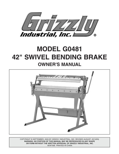
MODEL G0481 42" SWIVEL BENDING BRAKE - Grizzly Industrial Inc.
MODEL G0481 42" SWIVEL BENDING BRAKE - Grizzly Industrial Inc.
MODEL G0481 42" SWIVEL BENDING BRAKE - Grizzly Industrial Inc.
- No tags were found...

You also want an ePaper? Increase the reach of your titles
YUMPU automatically turns print PDFs into web optimized ePapers that Google loves.
<strong>MODEL</strong> <strong>G0481</strong>42" <strong>SWIVEL</strong> <strong>BENDING</strong> <strong>BRAKE</strong>OWNER'S ManualCopyright © SEPTEMBER, 2005 By <strong>Grizzly</strong> <strong>Industrial</strong>, <strong>Inc</strong>. Revised AUGUST, 2011(KN)Warning: No portion of this manual may be reproduced in any shapeOr form without the written approval of <strong>Grizzly</strong> <strong>Industrial</strong>, inc.#EW7566 printed in CHINA
This manual provides critical safety instructions on the proper setup,operation, maintenance, and service of this machine/tool. Save thisdocument, refer to it often, and use it to instruct other operators.Failure to read, understand and follow the instructions in this manualmay result in fire or serious personal injury—including amputation,electrocution, or death.The owner of this machine/tool is solely responsible for its safe use.This responsibility includes but is not limited to proper installation ina safe environment, personnel training and usage authorization,proper inspection and maintenance, manual availability and comprehension,application of safety devices, cutting/sanding/grinding toolintegrity, and the usage of personal protective equipment.The manufacturer will not be held liable for injury or property damagefrom negligence, improper training, machine modifications or misuse.Some dust created by power sanding, sawing, grinding, drilling, andother construction activities contains chemicals known to the Stateof California to cause cancer, birth defects or other reproductiveharm. Some examples of these chemicals are:• Lead from lead-based paints.• Crystalline silica from bricks, cement and other masonry products.• Arsenic and chromium from chemically-treated lumber.Your risk from these exposures varies, depending on how often youdo this type of work. To reduce your exposure to these chemicals:Work in a well ventilated area, and work with approved safety equipment,such as those dust masks that are specially designed to filterout microscopic particles.
Table of ContentsINTRODUCTION............................................................................................................................... 2Manual Accuracy........................................................................................................................ 2Contact Info................................................................................................................................ 2Identification................................................................................................................................ 3Machine Data Sheet................................................................................................................... 4SECTION 1: SAFETY....................................................................................................................... 5Additional Safety for Bending Brakes......................................................................................... 7SECTION 2: SET UP......................................................................................................................... 8Needed for Setup........................................................................................................................ 8Unpacking................................................................................................................................... 8Cleanup....................................................................................................................................... 8Site Considerations................................................................................................................... 10Lifting........................................................................................................................................ 11Mounting to Floor...................................................................................................................... 11SECTION 3: OPERATIONS............................................................................................................ 12Setback..................................................................................................................................... 12Clamping Pressure................................................................................................................... 14Bend Allowance........................................................................................................................ 14Basic Bending........................................................................................................................... 15Spacing Fingers........................................................................................................................ 15Setting the Adjustable Stops.................................................................................................... 16Aligning Fingers........................................................................................................................ 17SECTION 4: ACCESSORIES......................................................................................................... 18SECTION 5: MAINTENANCE......................................................................................................... 19Cleaning.................................................................................................................................... 19Unpainted Cast Iron.................................................................................................................. 19Lubrication................................................................................................................................ 19SECTION 6: SERVICE.................................................................................................................... 20Troubleshooting........................................................................................................................ 20Parts Breakdown...................................................................................................................... 21Parts List................................................................................................................................... 22WARRANTY CARD......................................................................................................................... 23WARRANTY & RETURNS.............................................................................................................. 25
INTRODUCTIONManual AccuracyContact InfoWe are proud to offer this manual with your newmachine! We've made every effort to be exactwith the instructions, specifications, drawings,and photographs of the machine we used whenwriting this manual. However, sometimes we stillmake an occasional mistake.Also, owing to our policy of continuous improvement,your machine may not exactly match themanual. If you find this to be the case, and the differencebetween the manual and machine leavesyou in doubt, check our website for the latestmanual update or call technical support for help.Before calling, find the manufacture date of yourmachine by looking at the date stamped into themachine ID label (see below). This will help usdetermine if the manual version you receivedmatches the manufacture date of your machine.We stand behind our machines. If you haveany questions or need help, use the informationbelow to contact us. Before contacting, please getthe serial number and manufacture date of yourmachine. This will help us help you faster.<strong>Grizzly</strong> Technical Support1203 Lycoming Mall CircleMuncy, PA 17756Phone: (570) 546-9663Email: techsupport@grizzly.comWe want your feedback on this manual. What didyou like about it? Where could it be improved?Please take a few minutes to give us feedback.<strong>Grizzly</strong> Documentation ManagerP.O. Box 2069Bellingham, WA 98227-2069Email: manuals@grizzly.comManufacture Dateof Your MachineFor your convenience, we post all available manualsand manual updates for free on our websiteat www.grizzly.com. Any updates to your modelof machine will be reflected in these documentsas soon as they are complete.-2- <strong>G0481</strong> 42" Swivel Bending Brake
IdentificationBHDEJCFAIGA. Bending Leaf—Swivels up to bend the workpiece.B. Clamping Leaf—Holds the clamping leaf fingers. Squeezes the workpiece against the block.C. Operating Handle—Used to raise and lower the bending leaf.D. Clamping Leaf Fingers—Adjustable dies that hold the workpiece against the clamping block.E. Bending Leaf Fingers—Adjustable dies that the workpiece is bent against.F. Clamping Pressure Turnbuckle—Adjusts clamping pressure, allowing for different gauges.G. Stop Collar—Used to lock bending angle.H. Quick Stop—Indicates the bending angle and can be used as an easily adjustable stop.I. Clamping Plate—Holds the bending leaf fingers.J. Clamping Block—Holds the workpiece against the clamping leaf.<strong>G0481</strong> 42" Swivel Bending Brake -3-
Machine Data SheetMACHINE DATASHEETCustomer Service #: (570) 546-9663 • To Order Call: (800) 523-4777 • Fax #: (800) 438-5901Model <strong>G0481</strong> 42" swivel bending <strong>BRAKE</strong>Design Type....................................... Floor Model Swivel Bending BrakeOverall Dimensions:Width................................................................................................52"Depth............................................................................................ 30 3 ⁄4"Height............................................................................................ 42 1 ⁄2"Net Weight................................................................................370 lbs.Footprint............................................................................31 1 ⁄2" x 45 1 ⁄4"Crate Size.................................................35 1 ⁄2" D x 63 3 ⁄4" W x 45 1 ⁄4" HShipping Weight........................................................................525 lbs.Finger Sizes:1 pc........................................................................................1"(25mm)1 pc................................................................................... 1 3 ⁄16"(30mm)1 pc.................................................................................... 1 3 ⁄8"(35mm)1 pc................................................................................... 1 9 ⁄16"(40mm)1 pc.................................................................................... 1 3 ⁄4"(45mm)1 pc...................................................................................... 2"(50mm)1 pc.................................................................................. 2 15 ⁄16"(75mm)1 pc................................................................................ 3 15 ⁄16"(100mm)1 pc................................................................................ 5 15 ⁄16"(150mm)2 pc.................................................................................. 9 7 ⁄8"(250mm)Capacities:Brake Range...........................................................................0° - 140°Maximum Width...............................................................................42"Maximum Height of Pan/Box Sides................................................ 1 1 ⁄2"Mild Steel.............................................................................. 16 GaugeAluminium............................................................................. 12 GaugeSoft Brass............................................................................. 14 GaugeAnnealed Phospor Bronze.................................................... 16 GaugeSoft Copper........................................................................... 14 GaugeHard Copper......................................................................... 16 GaugeConstruction:Fingers..................................Precision Ground Steel, Hardened EdgeBase.............................................................................................. SteelBending Leaf................................................................................ SteelClamping Leaf............................................................................... Steel-4- <strong>G0481</strong> 42" Swivel Bending Brake
SECTION 1: SAFETYFor Your Own Safety, Read InstructionManual Before Operating this MachineThe purpose of safety symbols is to attract your attention to possible hazardous conditions.This manual uses a series of symbols and signal words intended to convey the level of importanceof the safety messages. The progression of symbols is described below. Remember thatsafety messages by themselves do not eliminate danger and are not a substitute for properaccident prevention measures.Indicates an imminently hazardous situation which, if not avoided,WILL result in death or serious injury.Indicates a potentially hazardous situation which, if not avoided,COULd result in death or serious injury.NOTICEIndicates a potentially hazardous situation which, if not avoided,MAY result in minor or moderate injury. It may also be used to alertagainst unsafe practices.This symbol is used to alert the user to useful information aboutproper operation of the machine.OWNER’S MANUAL. Read and understandthis owner’s manual BEFORE using machine.Untrained users can be seriously hurt.EYE PROTECTION. Always wear ANSI-approvedsafety glasses or a face shield when operating orobserving machinery to reduce the risk of eyeinjury or blindness from flying particles. Everydayeyeglasses are not approved safety glasses.HAzARdOUS dUST. Dust created while usingmachinery may cause cancer, birth defects, orlong-term respiratory damage. Be aware of dusthazards associated with each workpiece material,and always wear a NIOSH-approved respirator toreduce your risk.WEARING PROPER APPAREL. Do not wearclothing, apparel, or jewelry that can becomeentangled in moving parts. Always tie back orcover long hair. Wear non-slip footwear to avoidaccidental slips which could cause a loss of workpiececontrol.HEARING PROTECTION. Always wear hearingprotection when operating or observiing loudmachinery. Extended exposure to this noisewithout hearing protection can cause permanenthearing loss.MENTAL ALERTNESS. Be mentally alert whenrunning machinery. Never operate under theinfluence of drugs or alcohol, when tired, or whendistracted.<strong>G0481</strong> 42" Swivel Bending Brake -5-
DISCONNECTING POWER SUPPLY.Alwaysdisconnectmachine from power supply before servicing,adjusting, or changing cutting tools (bits,blades,cutters,etc.).MakesureswitchisinOFFpositionbeforereconnectingtoavoidanunexpectedorunintentionalstart.APPROVED OPERATION. Untrained operatorscanbe seriously hurt by machinery. Only allowtrainedor properly supervised people to usemachine.When machine is not being used, disconnectpower, remove switch keys, or lock-outmachinetopreventunauthorizeduse—especiallyaroundchildren.Makeworkshopkidproof!DANGEROUS ENVIRONMENTS. Do not usemachineryin wet or rainy locations, clutteredareas,around flammables, or in poorly-lit areas.Keep work area clean, dry, and well-lighted tominimizeriskofinjury.ONLY USE AS INTENDED. Only use machineforits intended purpose. Never modify or altermachineforapurposenotintendedbythemanufacturerorseriousinjurymayresult!USE RECOMMENDED ACCESSORIES.Consultthisowner’smanualorthemanufacturerforrecommendedaccessories. Using improper accessorieswillincreasetheriskofseriousinjury.CHILDREN & BYSTANDERS. Keep childrenandbystandersasafedistanceawayfromworkarea.Stopusingmachineifchildrenorbystandersbecomeadistraction.REMOVE ADJUSTING TOOLS. Never leaveadjustmenttools,chuckkeys,wrenches,etc.inoronmachine—especiallynearmovingparts.Verifyremovalbeforestarting!SECURING WORKPIECE. When required, useclampsorvisestosecureworkpiece.Asecuredworkpieceprotectshandsandfreesbothofthemtooperatethemachine.FEED DIRECTION.Unlessotherwisenoted,feedworkagainst the rotation of blades or cutters.Feedinginthesamedirectionofrotationmaypullyourhandintothecut.FORCING MACHINERY.Donotforcemachine.Itwilldothejobsaferandbetterattherateforwhichitwasdesigned.GUARDS & COVERS. Guards and covers canprotectyou from accidental contact with movingpartsor flying debris. Make sure they are properlyinstalled,undamaged,andworkingcorrectlybeforeusingmachine.NEVER STAND ON MACHINE.Seriousinjuryoraccidentalcontact with cutting tool may occur ifmachineistipped.Machinemaybedamaged.STABLE MACHINE. Unexpectedmovementduringoperationsgreatlyincreasestheriskofinjuryandloss of control. Verify machines are stable/secure and mobile bases (if used) are lockedbeforestarting.AWKWARD POSITIONS. Keep proper footingandbalanceatalltimeswhenoperatingmachine.Donotoverreach!Avoidawkwardhandpositionsthatmake workpiece control difficult or increasetheriskofaccidentalinjury.UNATTENDED OPERATION. Never leavemachinerunningwhileunattended.Turnmachineoffandensureallmovingpartscompletelystopbeforewalkingaway.MAINTAIN WITH CARE.Followallmaintenanceinstructionsand lubrication schedules to keepmachineingoodworkingcondition.Animproperlymaintainedmachinemayincreasetheriskofseriousinjury.CHECK DAMAGED PARTS. Regularly inspectmachinefor damaged parts, loose bolts, misadjustedor mis-aligned parts, binding, or anyotherconditions that may affect safe operation.Alwaysrepairorreplacedamagedormis-adjustedpartsbeforeoperatingmachine.EXPERIENCING DIFFICULTIES. If at any timeyouare experiencing difficulties performing theintendedoperation, stop using the machine!Contact our Technical Support Department at(570)546-9663.-6- <strong>G0481</strong> 42" Swivel Bending Brake
SECTION 2: SET UPThis machine presentsserious injury hazardsto untrained users. Readthrough this entire manualto become familiar withthe controls and operationsbefore starting themachine!Wear safety glasses duringthe entire setup process!UnpackingThe Model <strong>G0481</strong> was carefully packed when itleft our warehouse. If you discover the machineis damaged after you have signed for delivery,please immediately call Customer Service at(570) 546-9663 for advice.Save the containers and all packing materials forpossible inspection by the carrier or its agent.Otherwise, filing a freight claim can be difficult.When you are completely satisfied with the conditionof your shipment, you should inventory thecontents.The Model <strong>G0481</strong> is aheavy machine. Seriouspersonal injury may occurif safe moving methodsare not followed. Tobe safe, you will needassistance and powerequipment when movingthe shipping crate andremoving the equipmentfrom the crate.Needed for SetupThe following are needed to complete the setupprocess, but are not included with your machine.DescriptionQty• Safety Glasses............................................ 1• Cleaner/Degreaser...................................... 1• Disposable Shop Rags ................ As Needed• Forklift w/Lifting Straps............................... 1• Additional People At Least.......................... 1• Mounting Hardware (Page 11) .... As Needed• Wrench or Socket 17mm............................. 1• Wrench or Socket 19mm............................ 2SUFFOCATION HAZARD!Keep children and pets awayfrom plastic bags or packingmaterials unpacked with thismachine. Discard immediately.CleanupThe unpainted surfaces of your machine arecoated with a heavy-duty rust preventative thatprevents corrosion during shipment and storage.This rust preventative works extremely well, but itwill take a little time to clean.Be patient and do a thorough job cleaning yourmachine. The time you spend doing this now willgive you a better appreciation for the proper careof your machine's unpainted surfaces.There are many ways to remove this rust preventative,but the following steps work well in a widevariety of situations. Always follow the manufacturer’sinstructions with any cleaning product youuse and make sure you work in a well-ventilatedarea to minimize exposure to toxic fumes.-8- <strong>G0481</strong> 42" Swivel Bending Brake
Before cleaning, gather the following:• Disposable Rags• Cleaner/degreaser (WD•40 works well)• Safety glasses & disposable gloves• Plastic paint scraper (optional)Basic steps for removing rust preventative:1. Put on safety glasses.2. Coat the rust preventative with a liberalamount of cleaner/degreaser, then let it soakfor 5–10 minutes.3. Wipe off the surfaces. If your cleaner/degreaser is effective, the rust preventativewill wipe off easily. If you have a plastic paintscraper, scrape off as much as you can first,then wipe off the rest with the rag.4. Repeat Steps 2–3 as necessary until clean,then coat all unpainted surfaces with a qualitymetal protectant to prevent rust.Gasoline and petroleumproducts have low flashpoints and can explodeor cause fire if used toclean machinery. Avoidusing these productsto clean machinery.Many cleaning solventsare toxic if inhaled. Onlywork in a well-ventilatedarea.To clean the fingers:1. Raise the clamping leaf to make sure there isno pressure on the fingers.2. Use a 6mm hex wrench to remove the clampingfingers as shown in Figure 1, but leavethe T-nuts in the guide slots.Cap ScrewT-NutFingerBlocksFigure 1. Removing finger blocks.3. Loosen the clamping block and remove thebending leaf fingers.4. Thoroughly clean the fingers and coat themliberally with a metal protectant.Note: For metal protectants, we recommendusing G96 ® GUN TREATMENT orBOESHIELD ® T-9 (see SECTION 4:ACCESSORIES on Page 18).5. Replace the fingers and secure them with thecap screws.NOTICEAvoid chlorine-based solvents, such asacetone or brake parts cleaner, that maydamage painted surfaces.<strong>G0481</strong> 42" Swivel Bending Brake -9-
Site ConsiderationsPhysical EnvironmentThe physical environment where your machineis operated is important for safe operation andthe longevity of its components. For best results,operate this machine in a dry environment that isfree from excessive moisture, hazardous chemicals,airborne abrasives, or extreme conditions.Extreme conditions for this type of machinery aregenerally those where the ambient temperaturerange exceeds 41°–104°F; the relative humidityrange exceeds 20–95% (non-condensing); or theenvironment is subject to vibration, shocks, orbumps.Space AllocationConsider the largest size of workpiece that willbe processed through this machine and provideenough space around the machine for adequateoperator material handling or the installation ofauxiliary equipment. With permanent installations,leave enough space around the machine to openor remove doors/covers as required by the maintenanceand service described in this manual.See below for required space allocation.Weight LoadRefer to the Machine Data Sheet for the weightof your machine. Make sure that the surface uponwhich the machine is placed will bear the weightof the machine, additional equipment that may beinstalled on the machine, and the heaviest workpiecethat will be used. Additionally, consider theweight of the operator and any dynamic loadingthat may occur when operating the machine.LightingLighting around the machine must be adequateenough that operations can be performed safely.Shadows, glare, or strobe effects that may distractor impede the operator must be eliminated.Children or untrained peoplemay be seriously injured bythis machine. Only install in anaccess restricted location.30 3 ⁄4"42 1 ⁄2"Figure 2. Machine dimensions.-10- <strong>G0481</strong> 42" Swivel Bending Brake
LiftingMounting to Floor• If you are unsure of how to lift this equipmentsafely, consult a qualified professional.• When lifting the bending brake, make surethe weight is supported evenly with two ormore lifting devices.• Make sure the body of the brake is bearingthe load (Figure 3).Do not operate the Model <strong>G0481</strong> unless ithas been mounted to the floor, or it could tipover on you, causing severe injury!Confirm that the bending brake works to yoursatisfaction using a small test piece, then mountthe bending brake to the floor. Make sure there isenough working room around the bending brakeand the mounting location is level to ensure accurateoperation.Floor mounting hardware is not included becausefloor materials vary. Research machine mountingoptions and choose the best method for yourapplication. Lag shield anchors with lag bolts, oranchor studs (Figures 4 & 5), are common methodsfor mounting machines to concrete floors.Figure 3. Swivel bending brake supportedevenly by two lifting straps.Note: Anchor studs are stronger and more permanentthan lag shield anchors; however, theystick out of the floor, causing difficulties if youdecide to move your bending brake later.Figure 4. Typical lag shield anchor and lag bolt.Figure 5. Typical anchor stud.<strong>G0481</strong> 42" Swivel Bending Brake -11-
SECTION 3: OPERATIONSDamage to your eyes, hands, and feet couldresult from using this machine without properprotective gear. Always wear safety glasses,protective gloves and footwear whenoperating this machine.SetbackNOTICEYou must include the thickness of foldededges or joints when determining the propersetback, or the brake may be damaged.Loose hair and clothingcould get caught inmachinery and cause seriouspersonal injury. Keeploose clothing and longhair away from movingmachinery.NOTICEIf you have never used this type of machineor equipment before, We strongly recommendthat you read books, trade magazines,or get formal training before beginningany projects. Regardless of the contentin this section, <strong>Grizzly</strong> <strong>Industrial</strong> willnot be held liable for accidents caused bylack of training.Before you begin any bending operation, considerthe differences of sheet metal gauges when tryingto achieve either sharp or rounded edges,and allow for the differences by adjusting thesetback.The setback is the distance from the forward edgeof the fingers to the edge of the bending leaf,as shown in Figure 6. The setback distance isdetermined by the gauge of the workpiece and thedesired radius of the bend.Normally, setback is adjusted at least 1 1 ⁄2–2times the thickness of the workpiece. Thickeror tempered workpieces will need a larger setback.Refer to material gauge capacities on theMACHINE DATA SHEET on Page 4.SetbackDistanceFingerBendingLeafClampingBlockFigure 6. Setback distance.Tools Needed:Qty17mm Wrench.................................................... 232mm or 1 ⁄4" Wrench........................................ 16mm Hex Wrench.............................................. 1-12- <strong>G0481</strong> 42" Swivel Bending Brake
To make minor setback adjustments to theclamping leaf:1. Unlock the clamping leaf, loosen the setbackadjustment lock bolts shown in Figure 7, androtate the setback adjustment cams evenlyto move the clamping fingers.Note: Make sure the finger edges are parallelwith the edge of the clamp block or yourbend will be distorted.3. Make minor adjustments with the setbackadjustment cams if necessary to make surethe finger edges are parallel with the edge ofthe clamp block.4. Retighten the cap screws before using.To make bending leaf adjustments:1. Loosen the lock bolts on both sides of thebending leaf (see Figure 9).SetbackAdjustmentCamLock BoltsSetbackAdjustmentLock BoltBendingLeaf SetbackAdjustment BoltFigure 7. Setback adjustment controls.2. Tighten the setback adjustment lock bolts.To make major setback adjustments:1. Unlock the clamping leaf.2. Loosen all of the setback adjustment capscrews like the one shown in Figure 8, thenadjust the finger block.SetbackCap Screw (MajorAdjustments)Figure 9. Bending leaf setback adjustments.2. Adjust the setback adjustment bolts (Figure9) on both ends of the bending leaf equally.Note: Use a permanent marker, paper correctionfluid, or fingernail polish to mark thesetback adjustment bolt on both sides. Thisstep will aid you in keeping track of the rotationsas you turn the bolts, so they remain aseven as possible.3. Retighten the lock bolts before using thebending brake.Finger BlockFigure 8. Setback adjustment cap screws.<strong>G0481</strong> 42" Swivel Bending Brake -13-
Clamping Pressure5. Loosen the cam shown in Figure 11 androtate it to fine tune the clamping pressure.Clamping pressure depends on the workpiecethickness. The ideal pressure will have medium/hard resistance and will lock the workpiece intoposition easily—much like a pair of Vice-Grips.This pressure is adjusted by adjusting the turnbuckles,shown in Figure 10, located on bothsides of the bending brake.TurnbuckleFine AdjustmentCamLockingNutsFigure 11. Clamping pressure fineadjustment cam.Bend AllowanceFigure 10. Clamping pressure turnbuckle.Tools Needed:Qty24mm or Adjustable Wrench.............................. 119mm Wrench.................................................... 117mm Wrench.................................................... 1To adjust the clamping pressure:1. Lock the clamping leaf with your workpiece inthe brake using the operating handle.— If the clamping pressure feels right, no furtheradjustments are necessary.— If the clamping pressure feels light, movethe turnbuckle clockwise.— If the clamping pressure feels hard, movethe turnbuckle counterclockwise.To bend metal objects accurately, you need toconsider the total length of each bend, especiallywhen more than one bend is required. This iscalled bend allowance.Subtract bend allowance from the sum of theworkpiece outside dimensions to obtain the overalllength and width of the blank needed to makea particular part.Exact allowances can only be obtained by trialdue to differences in sheet metal hardness,whether the bend is with or across the grain, anddifficulties in making an exact bend radius. Bendallowances accurate enough for average use maybe found in metalworking handbooks.2. Remove the workpiece from the brake, lockthe clamping leaf in place, then loosen thelocking nuts.3. Unlock the clamping leaf and turn the turnbucklea 1 ⁄2 turn in the needed direction.4. Lock the clamping leaf, tighten the lockingnuts, and repeat Step 1.-14- <strong>G0481</strong> 42" Swivel Bending Brake
Basic BendingSpacing FingersDo not operate the Model <strong>G0481</strong> unless ithas been mounted to the floor, or it could tipover on you, causing severe injury!The fingers can be spaced apart for clearancewhen making pans or boxes. This requiresremoving one or more of the fingers so that youcan space the others to match the width of yourpan or box as shown in Figure 12.Bending operations require the fingers to be parallelwith the edge of the clamping block and requirethe setback and clamping pressure to be correctlyadjusted for the thickness of the workpiece.To perform a basic bending operation:1. Mark the desired bend on the workpiece.2. Open the clamping leaf and insert theworkpiece between the fingers and the clampingblock.3. Align the fingers to the bend mark on theworkpiece, and clamp it in place.Note: Do not force the clamping handle. Ifthe handle is hard to put in the locked position,the pressure may need to be adjustedfor the sheet metal thickness (see ClampingPressure on Page 14).4. Lift the bending leaf until the workpiece hasreached the desired bend angle.5. Raise the clamping leaf and remove the bentworkpiece.Note: If a pan or box bend is desired, choose afinger or a selection of fingers that are as closeas possible to the length of the pan or box sidelengths.Hold onto the workpiece so it does not dropand hit you when it is released!Figure 12. Fingers spaced apart.Tools Needed:Qty8mm Hex Wrench.............................................. 1To space the fingers apart:1. Remove the cap screw from each of theclamping leaf fingers you decide to remove.2. Pull the fingers off the guide and set themaside.Note: Mix and match finger widths to equalthe width of the pan/box opening.3. Loosen the top cap screws of the fingers youneed to move, slide them across the guideso that you have adequate room for yourworkpiece on both sides, then retighten thecap screws.4. Remove the bending leaf fingers by looseningthe cap screws securing the clampingblock and sliding the fingers out.5. Adjust the bending leaf fingers as necessary,then retighten the cap screws in the clampingblock.<strong>G0481</strong> 42" Swivel Bending Brake -15-
Setting theAdjustable StopsThe Model <strong>G0481</strong> features two adjustable stopsthat limit the bending leaf travel, allowing you torepeat a bend at an exact angle.Tools Needed:Qty17mm Wrench.................................................... 110mm Wrench.................................................... 1To set the adjustable quick stop:To use the stop collar:1. Raise the bending leaf to the desired angleaccording to the quick stop and hold thebending leaf in place at the top of the bend.2. Thread the stop nut against the stop collarand tighten the lock nut against the bottomof the stop nut, as shown in Figure 14.Stop Collar1. Rotate the bending leaf all the way down.2. Loosen the hex bolt on the quick stopand rotate it down until it rests againstthe bending leaf, as shown in Figure 13.Stop NutLock NutPointerBendingAngle DialFigure 13. Setting adjustable stop.QuickStopFigure 14. Stop nut tightened against stop coloron stop rod.3. Check the stop collar by lowering the bendingleaf and then raising the bending leaf intoa bend. If the stop is working correctly, thebending leaf will stop in the same position asthe first bend.4. The stop rod can be attached in several locationsfor additional adjustment options, asshown in Figure 15.3. Loosen the pointer and align it with the180° mark on the bending angle dial.4. Tighten the quick stop hex bolt and raisethe bending leaf to the desired angle.The quick stop will stay in the raisedposition, allowing the bend to be repeated.5. To select and lock a different bendingangle, loosen the quick stop and repeatSteps 1-4.Figure 15. Stop rod attachment locations.-16- <strong>G0481</strong> 42" Swivel Bending Brake
Aligning FingersFinger alignment is critical for accuracy and toprevent dimples in bends.Tools Needed:Qty8mm Hex Wrench.............................................. 1To align the bending leaf fingers:1. Place a straightedge across the bending leaffingers as shown in Figure 17.Bending LeafFingersTo align a clamping leaf finger:1. Loosen the cap screw on the misalignedfinger enough to move it up or down withoutresistance.2. Make sure the bending leaf is lowered all theway and close the clamping leaf.Clamp Plate3. Push the finger firmly against the clampingblock and tighten the cap screw, as shown inFigure 16.Clamping BlockFigure 16. Tightening cap screw on finger.To align all of the clamping leaf fingers:Figure 17. Finger edges aligned.2. If an individual finger sticks out beyond theother fingers, loosen the cap screws in theclamp plate, wiggle the finger up or down,retighten and recheck finger alignment.3. Repeat Steps 1 & 2 if necessary.1. Loosen all of the cap screws on the fingersenough to move them up or down withoutresistance.2. Close the clamping leaf and lock the bendingleaf in place at 90°.3. Use the setback adjustments (Page 12) topush the fingers against the bending leaf.4. Tighten all of the cap screws on the fingers.5. Reset the setback as instructed on Page 12.<strong>G0481</strong> 42" Swivel Bending Brake -17-
ACCESSORIESSECTION 4: ACCESSORIESSome aftermarket accessories can beinstalled on this machine that could causeit to function improperly, increasing the riskof serious personal injury. To minimize thisrisk, only install accessories recommendedfor this machine by <strong>Grizzly</strong>.T23085—Pneumatic NibblerThe Model T23085 pneumatic nibbler cuts up to16 gauge steel without leaving burrs or deformededges. Features a lightweight aluminum housingwith adjustable die that can be turned to suitvarious cutting positions. Produces 3,800 strokesper minute at a working air pressure of 90 PSI.Average air consumption is 9.8 CFM.NOTICERefer to the newest copy of the <strong>Grizzly</strong>Catalog for other accessories available forthis machine.G5562—SLIPIT ® 1 Qt. GelG5563—SLIPIT ® 12 oz SprayG2871—Boeshield ® T-9 12 oz SprayG2870—Boeshield ® T-9 4 oz SprayH3788—G96 ® Gun Treatment 12 oz SprayH3789—G96 ® Gun Treatment 4.5 oz SprayFigure 19. Model T23085 Pneumatic Nibbler.10" Aviation Tin SnipsG8189—LeftG8190—StraightG8191—RightG8782—3 Piece SetPrecision-machined, hardened steel cutting jawsensure quality results. Color coded to providequick identification, these snips feature thick gripsfor cutting comfort and a positive lock.Figure 18. Recommended products for protectingunpainted cast iron/steel part on machinery.Figure 20. 10" Aviation Tin Snips.-18- <strong>G0481</strong> 42" Swivel Bending Brake
SECTION 5: MAINTENANCECleaningCleaning the Model <strong>G0481</strong> is relatively easy.Vacuum metal shavings and wipe off oil and dustwith a dry cloth. Treat all unpainted cast iron andsteel with a non-staining lubricant after cleaning.Unpainted Cast IronTo prevent rust, all unpainted cast iron surfaceson the Model <strong>G0481</strong> should be regularlymaintained with a surface protectant like G96 ®GUN TREATMENT or BOESHIELD ® T-9 (seeSECTION 4: ACCESSORIES on Page 18 formore details).LubricationThe pivot points indicated in Figures 21 and 22must be lubricated daily or each time the bendingbrake is used with a light machine oil.Figure 21. Pivot point locations.Figure 22. Clamping leaf lubrication.<strong>G0481</strong> 42" Swivel Bending Brake -19-
SECTION 6: SERVICEReview the troubleshooting and procedures in this section to fix your machine if a problem develops. If youneed replacement parts or you are unsure of your repair skills, then feel free to call our Technical Supportat (570) 546-9663.TroubleshootingSymptom Possible Cause Possible SolutionTapered bend or aradius change along thelength of the bend.1. Clamping leaf fingers not aligned withthe edge of the clamping block.2. Bending leaf setback is to far from theclamping v.1. Align the clamping leaf as instructed inSetback section on Page 12.2. Adjust the setback as instructed inSetback section beginning on Page 12.Dimple(s) in the bend. 1. One or more fingers out of alignment. 1. Align the fingers (see Page 17).Angle is not accurate oris not repeatable.Moving the bending leafor clamping leaf is extradifficult.Cannot complete thedesired bend, incorrectradius, or cracked material.Workpiece is not heldsecurely.Finished workpiece istoo short.Fingers are stucktogether or nuts on thestop rod will not move.1. Quick stop pointer is not adjusted correctly.2. Quick stop is not tightened down.3. Stop nut on the stop rod is not adjustedcorrectly.4. The lock nut is not tightened againstthe stop nut on the stop rod.1. Hinges are gummed up.2. Attempting to bend too thick of material.1. Not enough setback.2. Attempting to bend too thick of material.1. Adjust the quick stop pointer (seePage 16).2. Tighten the quick stop (see Page 16).3. Adjust the stop nut (see Page 16).4. Tighten the lock nut against the stopnut to prevent the angle from changing(see Page 16).1. Clean and lubricate the pivot points(see Page 18).2. Refer to material gauge capacities onthe MACHINE DATA SHEET on Page 4.1. Adjust the setback to 1 1 ⁄2–2 times thethickness of the workpiece (see Page 12).2. Refer to material gauge capacities onthe MACHINE DATA SHEET on Page 4.1. <strong>Inc</strong>orrect clamping pressure. 1. Adjust the clamping pressure toaccommodate the gauge of metalused (see Page 14).1. Inadequate bend allowance. 1. Lay out the workpiece with enoughmaterial to compensate for the lengthof the bend.1. The waxy oil used as a protectantduring shipping was not removedduring set-up.1. Use a degreaser to clean off the waxyoil (see Page 8).-20- <strong>G0481</strong> 42" Swivel Bending Brake
Parts Breakdown12223372056728 29302421113525262748323713163683323118194140113812391734344434214464515495010495147<strong>G0481</strong> 42" Swivel Bending Brake -21-
Parts ListREF PART # DESCRIPTION REF PART # DESCRIPTION1 P0481001 CLAMPING LEAF FRAME 12 P0481012 CLAMPING LEAF HANDLE2 P0481002 CROSSBEAM 13 P0481013 CLAMPING LEAF ADJ BLOCK3 P0481003 STAND 14 P0481014 RT <strong>BENDING</strong> LEAF ADJ PLATE4 P0481004 <strong>BENDING</strong> LEAF 15 P0481015 LT <strong>BENDING</strong> LEAF ADJ PLATE5 P0481005 T-SLOT PLATE 16 P0481016 QUICK STOP6 P0481006 CLAMPING LEAF FINGER SET 17 P0481017 STOP ROD6-1 P0481006-1 25MM FINGER 18 P0481018 STOP COLLAR BRACKET6-2 P0481006-2 30MM FINGER 19 P0481019 STOP COLLAR6-3 P0481006-3 35MM FINGER 20 P0481020 FENDER WASHER 8MM6-4 P0481006-4 40MM FINGER 21 P0481021 ECCENTRIC SLEEVE6-5 P0481006-5 45MM FINGER 22 PSB31M CAP SCREW M8-1.25 X 256-6 P0481006-6 50MM FINGER 23 PB87M HEX BOLT M8-1.25 X 156-7 P0481006-7 75MM FINGER 24 PB38M HEX BOLT M12-1.75 X 606-8 P0481006-8 100MM FINGER 25 P0481025 T-NUT M8-1.256-9 P0481006-9 150MM FINGER 26 PSB11M CAP SCREW M8-1.25 X 166-10 P0481006-10 250MM FINGER 27 PSB60M CAP SCREW M8-1.25 X 557 P0481007 CLAMPING BLOCK SET 28 P0481028 ECCENTRIC SHAFT7-1 P0481007-1 25MM CLAMPING BLOCK 29 PB27M HEX BOLT M12-1.75 X 307-2 P0481007-2 30MM CLAMPING BLOCK 30 P0481030 ROUND PIN 8 X 507-3 P0481007-3 35MM CLAMPING BLOCK 31 P0481031 BUSHING7-4 P0481007-4 40MM CLAMPING BLOCK 32 PB27M HEX BOLT M12-1.75 X 307-5 P0481007-5 45MM CLAMPING BLOCK 33 PB49M HEX BOLT M12-1.75 X 207-6 P0481007-6 50MM CLAMPING BLOCK 34 PB27M HEX BOLT M12-1.75 X 307-7 P0481007-7 75MM CLAMPING BLOCK 35 PB02M HEX BOLT M6-1 X 127-8 P0481007-8 100MM CLAMPING BLOCK 36 P0481036 BUSHING7-9 P0481007-9 150MM CLAMPING BLOCK 37 PW06M FLAT WASHER 12MM7-10 P0481007-10 250MM CLAMPING BLOCK 38 P0481038 BUSHING8 P0481008 TRANSMISSION BAR 39 PB87M HEX BOLT M8-1.25 X 159 P0481009 <strong>BENDING</strong> LEAF FINGER SET 40 P0481040 BUSHING9-1 P0481009-1 25MM <strong>BENDING</strong> LEAF FINGER 41 PEC03M E-CLIP 10MM9-2 P0481009-2 30MM <strong>BENDING</strong> LEAF FINGER 42 P0481042 STOP NUT M10-1.59-3 P0481009-3 35MM <strong>BENDING</strong> LEAF FINGER 43 PN02M HEX NUT M10-1.59-4 P0481009-4 40MM <strong>BENDING</strong> LEAF FINGER 44 PB34M HEX BOLT M10-1.5 X 609-5 P0481009-5 45MM <strong>BENDING</strong> LEAF FINGER 45 PB33M HEX BOLT M12-1.75 X 509-6 P0481009-6 50MM <strong>BENDING</strong> LEAF FINGER 46 PB27M HEX BOLT M12-1.75 X 309-7 P0481009-7 75MM <strong>BENDING</strong> LEAF FINGER 47 PSB31M CAP SCREW M8-1.25 X 259-8 P0481009-8 100MM <strong>BENDING</strong> LEAF FINGER 48 PN09M HEX NUT M12-1.759-9 P0481009-9 150MM <strong>BENDING</strong> LEAF FINGER 49 P0481049 <strong>G0481</strong> ID LABEL9-10 P0481009-10 250MM <strong>BENDING</strong> LEAF FINGER 50 PLABEL11 SAFETY GLASSES 2" X 3 5/16"10 P0481010 CLAMP PLATE 51 P0481051 DEBURR LABEL11 P0481011 TURNBUCKLESafety labels warn about machine hazards and ways to prevent injury. The owner of this machineMUST maintain the original location and readability of the labels on the machine. If any label isremoved or becomes unreadable, REPLACE that label before using the machine again. Contact<strong>Grizzly</strong> at (800) 523-4777 or www.grizzly.com to order new labels.-22- <strong>G0481</strong> 42" Swivel Bending Brake
WARRANTY CARDWARRANTY CARDName _____________________________________________________________________________Street _____________________________________________________________________________City _______________________ State _________________________ Zip _____________________Phone # ____________________ Email ________________________ Invoice # _________________Model # ____________________ Order # _______________________ Serial # __________________The following information is given on a voluntary basis. It will be used for marketing purposes to help us developbetter products and services. Of course, all information is strictly confidential.1. How did you learn about us?____ Advertisement ____ Friend ____ Catalog____ Card Deck ____ Website ____ Other:CUT ALONG DOTTED LINE2. Which of the following magazines do you subscribe to?____ Cabinetmaker & FDM____ Family Handyman____ Hand Loader____ Handy____ Home Shop Machinist____ Journal of Light Cont.____ Live Steam____ Model Airplane News____ Old House Journal____ Popular Mechanics____ Popular Science____ Popular Woodworking____ Precision Shooter____ Projects in Metal____ RC Modeler____ Rifle____ Shop Notes____ Shotgun News____ Today’s Homeowner____ Wood3. What is your annual household income?____ $20,000-$29,000 ____ $30,000-$39,000 ____ $40,000-$49,000____ $50,000-$59,000 ____ $60,000-$69,000 ____ $70,000+4. What is your age group?____ 20-29 ____ 30-39 ____ 40-49____ 50-59 ____ 60-69 ____ 70+____ Wooden Boat____ Woodshop News____ Woodsmith____ Woodwork____ Woodworker West____ Woodworker’s Journal____ Other:5. How long have you been a woodworker/metalworker?____ 0-2 Years ____ 2-8 Years ____ 8-20 Years ____20+ Years6. How many of your machines or tools are <strong>Grizzly</strong>?____ 0-2 ____ 3-5 ____ 6-9 ____10+7. Do you think your machine represents a good value? _____Yes _____No8. Would you recommend <strong>Grizzly</strong> <strong>Industrial</strong> to a friend? _____Yes _____No9. Would you allow us to use your name as a reference for <strong>Grizzly</strong> customers in your area?Note: We never use names more than 3 times. _____Yes _____No10. Comments: ________________________________________________________________________________________________________________________________________________________________________________________________________________________________________________________________________________________________________________________
FOLD ALONG DOTTED LINEPlaceStampHereGRIZZLY INDUSTRIAL, INC.P.O. BOX 2069BELLINGHAM, WA 98227-2069FOLD ALONG DOTTED LINESend a <strong>Grizzly</strong> Catalog to a friend:Name_______________________________Street_______________________________City______________State______Zip______TAPE ALONG EDGES--PLEASE DO NOT STAPLE
WARRANTY & RETURNS<strong>Grizzly</strong> <strong>Industrial</strong>, <strong>Inc</strong>. warrants every product it sells for a period of 1 year to the original purchaser fromthe date of purchase. This warranty does not apply to defects due directly or indirectly to misuse, abuse,negligence, accidents, repairs or alterations or lack of maintenance. This is <strong>Grizzly</strong>’s sole written warrantyand any and all warranties that may be implied by law, including any merchantability or fitness, for any particularpurpose, are hereby limited to the duration of this written warranty. We do not warrant or representthat the merchandise complies with the provisions of any law or acts unless the manufacturer so warrants.In no event shall <strong>Grizzly</strong>’s liability under this warranty exceed the purchase price paid for the product andany legal actions brought against <strong>Grizzly</strong> shall be tried in the State of Washington, County of Whatcom.We shall in no event be liable for death, injuries to persons or property or for incidental, contingent, special,or consequential damages arising from the use of our products.To take advantage of this warranty, contact us by mail or phone and give us all the details. We will then issueyou a “Return Number,’’ which must be clearly posted on the outside as well as the inside of the carton. Wewill not accept any item back without this number. Proof of purchase must accompany the merchandise.The manufacturers reserve the right to change specifications at any time because they constantly strive toachieve better quality equipment. We make every effort to ensure that our products meet high quality anddurability standards and we hope you never need to use this warranty.Please feel free to write or call us if you have any questions about the machine or the manual.Thank you again for your business and continued support. We hope to serve you again soon.
Buy Direct and Save with <strong>Grizzly</strong> ® – Trusted, Proven and a Great Value!~Since 1983~Visit Our Website Today ForCurrent Specials!ORDER24 HOURS A DAY!1-800-523-4777