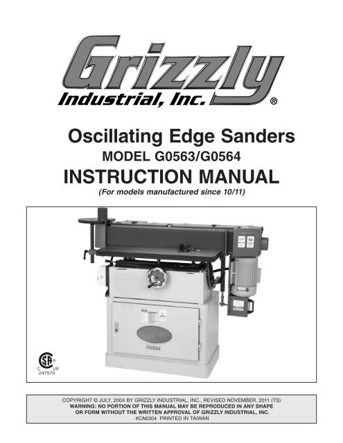
Oscillating Edge Sanders InStructIOn ManuaL - Grizzly.com
Oscillating Edge Sanders InStructIOn ManuaL - Grizzly.com
Oscillating Edge Sanders InStructIOn ManuaL - Grizzly.com
You also want an ePaper? Increase the reach of your titles
YUMPU automatically turns print PDFs into web optimized ePapers that Google loves.
INTRODUCTION................................................ 2Foreword........................................................ 2Contact Info.................................................... 2G0563 Machine Data Sheet.......................... 3G0564 Machine Data Sheet.......................... 5Machine Features........................................... 7SECTION 1: SAFETY........................................ 8Safety Instructions for Machinery................... 8Additional Safety for <strong>Oscillating</strong> <strong>Edge</strong>Sander.......................................................... 10SECTION 2: POWER SUPPLY....................... 11Availability.................................................. 11Full-Load Current Rating............................ 11Circuit Requirements for 240V................... 11Grounding Instructions............................... 12Extension Cords......................................... 12SECTION 3: SET UP....................................... 13About this Section........................................ 13Items Needed for Set Up.............................. 13Unpacking..................................................... 14Site Considerations...................................... 14Inventory....................................................... 15Hardware Recognition Chart........................ 16Clean Up...................................................... 17Installing Belt................................................ 17Back Stop..................................................... 18Dust Port...................................................... 18Dust Port Cover............................................ 19Dust Collection............................................. 19Sanding Spindle........................................... 20Belt Tracking................................................ 21Test Run....................................................... 21Table of ContentsSECTION 4: OPERATIONS............................ 22Sanding Belts............................................... 22Emergency Stop Button............................... 22Platen Angle Adjustment.............................. 23Table Adjustment......................................... 23Miter Gauge.................................................. 24Fence............................................................ 25Spindle Table Height.................................... 25Spindle Sanding........................................... 26<strong>Edge</strong> & End Sanding.................................... 26SECTION 5: ACCESSORIES.......................... 27SECTION 6: MAINTENANCE.......................... 29General......................................................... 29Lubrication.................................................... 29Tables........................................................... 30Rack and Pinion Gear.............................. 30Grease Fittings & Oil Ports..................... 30Spindle Connector........................................ 31Eccentric....................................................... 31Maintenance Log.......................................... 32SECTION 7: SERVICE.................................... 33About Service............................................... 33Calibrating Angle Gauge.............................. 33Removing Drive Roller................................. 34G0563 Wiring Diagram................................. 35G0564 Wiring Diagram................................. 36G0563 Parts Breakdown.............................. 37G0564 Parts Breakdown.............................. 41G0564 Parts List........................................... 44Troubleshooting Machine............................. 45Troubleshooting Sanding............................. 46WARRANTY AND RETURNS......................... 49Model G0563/G0564 (Mfg. Since 10/11) -1-
Table InformationTable Length........................................................................................................................................ 26-7/8 in.Table Width................................................................................................................................................ 12 in.Table Thickness.................................................................................................................................... 1-1/4 in.Table Travel........................................................................................................................................... 3-3/4 in.Floor To Table Height............................................................................................................ 35-3/4 – 39-1/2 in.End Table Length................................................................................................................................ 11-1/2 in.End Table Width........................................................................................................................................ 10 in.End Table Thickness................................................................................................................................ 3/4 in.End Table Travel....................................................................................................................................... 10 in.Platen InformationPlaten Type.............................................................................................................................. Graphite CoatedPlaten Length...................................................................................................................................... 30-1/4 in.Platen Width.......................................................................................................................................... 6-3/4 in.ConstructionTable....................................................................................................................... Precision-Ground Cast IronFrame......................................................................................................................................................... SteelBase........................................................................................................................................................... SteelDrive Roller......................................................................................................................................... AluminumIdler Roller.............................................................................................................................................. RubberPaint Type/Finish....................................................................................................................... Powder CoatedOther Related InformationNo Of Dust Ports.............................................................................................................................................. 2Dust Port Size.............................................................................................................................................. 4 in.Belt Release................................................................................................................................ Quick ReleaseDrive Roller Size.......................................................................................................................................... 7 in.Idler Roller Size..................................................................................................................................... 3-7/8 in.Other Specifications:Features:Country Of Origin ............................................................................................................................................. TaiwanWarranty ........................................................................................................................................................... 1 YearApproximate Assembly & Setup Time ........................................................................................................ 15 MinutesSerial Number Location .................................................................................................................... ID Label on BaseSound Rating ..................................................................................................................................................... 90 dBISO 9001 Factory .................................................................................................................................................... NoCSA Certified ......................................................................................................................................................... YesSanding Surface Tilts Vertical to HorizontalT-Slot Table and Miter GaugeQuick Release Belt Tension LeverGraphite Coated Platen<strong>Oscillating</strong> Sanding SurfacesSanding Belt Oscillates at 52 Cycles per MinuteIncludes 3 Spindles Drums: 1 1/2", 2", 3" x 4 1/2"Platen Tilts 0 to 90 degrees (5 deg. Scale)Model G0563The information contained herein is deemed accurate as of 6/19/2014 and represents our most recent product specifications.Due to our ongoing improvement efforts, this information may not accurately describe items previously purchased.PAGE 2 OF 2-4- Model G0563/G0564 (Mfg. Since 10/11)
MACHINE DATASHEETCustomer Service #: (570) 546-9663 · To Order Call: (800) 523-4777 · Fax #: (800) 438-5901MODEL G0564 OSCILLATING EDGE SANDER 3 HPProduct Dimensions:Weight.............................................................................................................................................................. 495 lbs.Width (side-to-side) x Depth (front-to-back) x Height........................................................................... 60 x 28 x 49 in.Footprint (Length x Width)..................................................................................................................... 32 x 19-1/2 in.Shipping Dimensions:Type.......................................................................................................................................................... Wood CrateContent........................................................................................................................................................... MachineWeight.............................................................................................................................................................. 597 lbs.Length x Width x Height....................................................................................................................... 58 x 31 x 44 in.Electrical:Motors:MainPower Requirement........................................................................................................... 240V, Single-Phase, 60 HzPrewired Voltage.................................................................................................................................................. 240VFull-Load Current Rating........................................................................................................................................ 11AMinimum Circuit Size.............................................................................................................................................. 15ASwitch........................................................................................................... Magnetic Contactor and Overload RelaySwitch Voltage..................................................................................................................................................... 220VCord Length.......................................................................................................................................................... 10 ft.Cord Gauge.................................................................................................................................................... 12 AWGPlug Included........................................................................................................................................................... NoRe<strong>com</strong>mended Plug/Outlet Type............................................................................................................... NEMA 6-15Type.................................................................................................................. TEFC Capacitor Start InductionHorsepower................................................................................................................................................ 3 HPVoltage....................................................................................................................................................... 240VPhase....................................................................................................................................................... SingleAmps............................................................................................................................................................ 11ASpeed................................................................................................................................................ 1725 RPMCycle......................................................................................................................................................... 60 HzNumber of Speeds............................................................................................................................................ 1Power Transfer ............................................................................................................................... Direct DriveBearings................................................................................................. Shielded and Permanently LubricatedMain Specifications:Operation InformationSanding Belt Speed........................................................................................................................... 3150 FPMSanding Belt Oscillations.......................................................................................................................... 3/4 in.Sanding Belt Length................................................................................................................................ 108 in.Sanding Belt Width...................................................................................................................................... 6 in.Sanding Belt Tilt................................................................................................................................ 0 - 90 deg.Model G0564The information contained herein is deemed accurate as of 11/23/2011 and represents our most recent product specifications.Due to our ongoing improvement efforts, this information may not accurately describe items previously purchased.PAGE 1 OF 2Model G0563/G0564 (Mfg. Since 10/11) -5-
Table InformationTable Length........................................................................................................................................ 35-1/2 in.Table Width................................................................................................................................................ 12 in.Table Thickness.................................................................................................................................... 1-1/2 in.Table Travel................................................................................................................................................. 4 in.Floor To Table Height............................................................................................................ 35-3/4 - 39-3/4 in.End Table Length................................................................................................................................ 11-1/2 in.End Table Width........................................................................................................................................ 10 in.End Table Thickness................................................................................................................................ 3/4 in.End Table Travel....................................................................................................................................... 10 in.Platen InformationPlaten Type.................................................................................................................... Steel wih Graphite PadPlaten Length...................................................................................................................................... 39-3/4 in.Platen Width.......................................................................................................................................... 6-3/4 in.Platen Travel..................................................................................................................................... 0 - 90 deg.ConstructionTable....................................................................................................................... Precision Ground Cast IronFrame.............................................................................................................................................. Sheet MetalBase................................................................................................................................................ Sheet MetalDrive Roller......................................................................................................................................... AluminumIdler Roller.............................................................................................................................................. RubberMiter Block.......................................................................................................................................... AluminumPaint........................................................................................................................................... Powder CoatedOther Related InformationNo Of Dust Ports.............................................................................................................................................. 2Dust Port Size.............................................................................................................................................. 4 in.Belt Release...................................................................................................................... Quick Release LeverDrive Roller Size.......................................................................................................................................... 7 in.Idler Roller Size..................................................................................................................................... 3-7/8 in.Other Specifications:Features:Country Of Origin ............................................................................................................................................. TaiwanWarranty ........................................................................................................................................................... 1 YearSerial Number Location ........................................................................................................................... On the BaseAssembly Time ........................................................................................................................................... 10 MinutesSound Rating ..................................................................................................................................................... 90 dBSanding Surfaces Tilts Vertical and HorizontalT-Slot Table and Miter GaugeQuick Belt Release LeverGraphite Coated Platen<strong>Oscillating</strong> Sanding SurfacesSanding Belt Oscillates at 52 Cycles per MinuteIncludes 3 Sanding Drums: 1 1/2", 2", 3" x 4 1/2"Platen Tilts 0 to 90 degrees (5 deg. Scale)Model G0564The information contained herein is deemed accurate as of 11/23/2011 and represents our most recent product specifications.Due to our ongoing improvement efforts, this information may not accurately describe items previously purchased.PAGE 2 OF 2-6- Model G0563/G0564 (Mfg. Since 10/11)
Machine Features12345616715814139121110Figure 1. Main Features of the G0563/G0564.1. Sanding Spindle Table2. Sanding Spindle3. Belt Access Door4. Emergency Stop Switch5. Back Stop6. Dust Port7. Motor8. Angle Adjustment & Lock Handle9. Belt Tracking Adjustment10. Vertical Adjustment Lock Handles11. Vertical Adjustment Handwheel12. Storage Compartment13. Sanding Table14. ON/OFF Switch15. Table Lock Levers16. Spindle Table Adjustment Lock HandleFor Your Own Safety Read Instruction Manual Before Operating Sawa) Wear eye protection.b) Support workpiece with miter gauge, backstop or worktable.c) Maintain 1 ⁄16" in maximum clearance between table and sanding belt.d) Avoid kickback by sanding in accordance with the directional arrows.Model G0563/G0564 (Mfg. Since 10/11) -7-
For Your Own Safety, Read InstructionManual Before Operating This MachineThe purpose of safety symbols is to attract your attention to possible hazardous conditions.This manual uses a series of symbols and signal words intended to convey the level of importanceof the safety messages. The progression of symbols is described below. Remember thatsafety messages by themselves do not eliminate danger and are not a substitute for properaccident prevention measures. Always use <strong>com</strong>mon sense and good judgment.NOTICESECTION 1: SafETYIndicates an imminently hazardous situation which, if not avoided,WILL result in death or serious injury.Indicates a potentially hazardous situation which, if not avoided,COULD result in death or serious injury.Indicates a potentially hazardous situation which, if not avoided,MAY result in minor or moderate injury. It may also be used to alertagainst unsafe practices.This symbol is used to alert the user to useful information aboutproper operation of the machine.Safety Instructions for MachineryOWNER’S MANUAL. Read and understand thisowner’s manual BEFORE using machine.TRAINED OPERATORS ONLY. Untrained operatorshave a higher risk of being hurt or killed.Only allow trained/supervised people to use thismachine. When machine is not being used, disconnectpower, remove switch keys, or lock-outmachine to prevent unauthorized use—especiallyaround children. Make workshop kid proof!DANGEROUS ENVIRONMENTS. Do not usemachinery in areas that are wet, cluttered, or havepoor lighting. Operating machinery in these areasgreatly increases the risk of accidents and injury.MENTAL ALERTNESS REQUIRED. Full mentalalertness is required for safe operation of machinery.Never operate under the influence of drugs oralcohol, when tired, or when distracted.ELECTRICAL EQUIPMENT INJURY RISKS. Youcan be shocked, burned, or killed by touching liveelectrical <strong>com</strong>ponents or improperly groundedmachinery. To reduce this risk, only allow qualifiedservice personnel to do electrical installation orrepair work, and always disconnect power beforeaccessing or exposing electrical equipment.DISCONNECT POWER FIRST. Always disconnectmachine from power supply BEFORE makingadjustments, changing tooling, or servicing machine.This prevents an injury risk from unintended startupor contact with live electrical <strong>com</strong>ponents.EYE PROTECTION. Always wear ANSI-approvedsafety glasses or a face shield when operating orobserving machinery to reduce the risk of eyeinjury or blindness from flying particles. Everydayeyeglasses are not approved safety glasses.-8- Model G0563/G0564 (Mfg. Since 10/11)
WEARING PROPER APPAREL. Do not wearclothing,apparel or jewelry that can be<strong>com</strong>eentangledin moving parts. Always tie back orcoverlonghair.Wearnon-slipfootweartoavoidaccidentalslips,whichcouldcauselossofworkpiececontrol.hAzARdOus dusT. Dust created while usingmachinerymay cause cancer, birth defects, orlong-termrespiratorydamage.Beawareofdusthazardsassociatedwitheachworkpiecematerial,andalwayswearaNIOSH-approvedrespiratortoreduceyourrisk.hEARING PROTECTION. Always wear hearingprotection when operating or observing loudmachinery.Extended exposure to this noisewithouthearingprotectioncancausepermanenthearingloss.REMOVE AdJusTING TOOLs. Tools left onmachinerycan be<strong>com</strong>e dangerous projectilesuponstartup.Neverleavechuckkeys,wrenches,or any other tools on machine. Always verifyremovalbeforestarting!INTENdEd usAGE. Only use machine for itsintendedpurposeandnevermakemodificationsnotapproved by <strong>Grizzly</strong>. Modifying machine orusingit differently than intended may result inmalfunctionormechanicalfailurethatcanleadtoseriouspersonalinjuryordeath!AWKWARd POsITIONs. Keep proper footingandbalanceatalltimeswhenoperatingmachine.Donotoverreach!Avoidawkwardhandpositionsthatmake workpiece control difficult or increasetheriskofaccidentalinjury.ChILdREN & BYsTANdERs. Keepchildrenandbystandersatasafedistancefromtheworkarea.Stopusingmachineiftheybe<strong>com</strong>eadistraction.GuARds & COVERs.Guardsandcoversreduceaccidentalcontact with moving parts or flyingdebris.Make sure they are properly installed,undamaged,andworkingcorrectly.FORCING MAChINERY.Donotforcemachine.Itwilldothejobsaferandbetterattherateforwhichitwasdesigned.NEVER sTANd ON MAChINE. Serious injurymayoccur if machine is tipped or if the cuttingtoolisunintentionallycontacted.sTABLE MAChINE. Unexpectedmovementduringoperation greatly increases risk of injury orlossofcontrol.Beforestarting,verifymachineisstableandmobilebase(ifused)islocked.usE RECOMMENdEd ACCEssORIEs.Consultthisowner’smanualorthemanufacturerforre<strong>com</strong>mendedaccessories. Using improper accessorieswillincreasetheriskofseriousinjury.uNATTENdEd OPERATION. To reduce theriskof accidental injury, turn machine off andensureall moving parts <strong>com</strong>pletely stop beforewalkingaway. Never leave machine runningwhileunattended.MAINTAIN WITh CARE.Followallmaintenanceinstructionsand lubrication schedules to keepmachinein good working condition. A machinethatis improperly maintained could malfunction,leadingtoseriouspersonalinjuryordeath.ChECK dAMAGEd PARTs. Regularly inspectmachinefor any condition that may affect safeoperation.Immediatelyrepairorreplacedamagedormis-adjustedpartsbeforeoperatingmachine.MAINTAIN POWER CORds. When disconnectingcord-connected machines from power, grabandpulltheplug—NOTthecord.Pullingthecordmaydamage the wires inside. Do not handlecord/plugwithwethands.Avoidcorddamagebykeepingitawayfromheatedsurfaces,hightrafficareas,harshchemicals,andwet/damplocations.EXPERIENCING dIFFICuLTIEs. If at any timeyouexperiencedifficultiesperformingtheintendedoperation,stopusingthemachine!ContactourTechnicalSupportat(570)546-9663.Model G0563/G0564 (Mfg. Since 10/11) -9-
Additional Safety for <strong>Oscillating</strong><strong>Edge</strong> SanderREAD <strong>ManuaL</strong>. This manual contains properoperating and safety procedures for thismachine.WORKPIECE PRESSURE: Do not jam theworkpiece against the sanding surfaces. Firmlygrasp the workpiece in both hands and ease itagainst the belt/spindle using light pressure.CLOthING: Do not wear loose clothing whileoperating this machine. Roll up or button sleevesat the cuff.hanD PLacEMENT: Do not place hands near,or in contact with, sanding surfaces during operation.WORKPIECE HANDLING: Grip the workpiecewith both hands.MAIntEnancE: Perform machine inspectionsand maintenance promptly as required.unattENDED MachINE: Never leave themachine running unattended.SanDING BELTS/DruMS: Replace sandingbelts and drums promptly as needed.WORKPIECE QuantITY: Never sand more thanone piece of stock at a time.FOREIGN MatERIAL: Always inspect stock fornails, staples, knots, and other imperfections thatcould be dislodged and thrown from the machineduring sanding operations.DUST COLLEctION: Never operate the sanderwithout an adequate dust collection system inplace and running.DIREctION: Never sand tapered or pointed stockwith the point facing the feed direction.POWER DISCOnnEct: Disconnect the machinefrom the power source before changing the sandingbelt or sleeve.TEST RUN: Test run the machine before startingany work.Like all machinery there is potential dangerwhen operating this machine. Accidents arefrequently caused by lack of familiarity orfailure to pay attention. Use this machinewith respect and caution to decrease therisk of operator injury. If normal safety precautionsare overlooked or ignored, seriouspersonal injury may occur.No list of safety guidelines can be <strong>com</strong>plete.Every shop environment is different. Alwaysconsider safety first, as it applies to yourindividual working conditions. Use this andother machinery with caution and respect.Failure to do so could result in serious personalinjury, damage to equipment, or poorwork results.-10- Model G0563/G0564 (Mfg. Since 10/11)
SECTION 3: SET UPAbout this SectionThe purpose of this section is to guide you throughthe required steps to get your machine out of itspackaging and into operating condition.If you do not read thisentire manual beforeoperating machine, youwill greatly increase yourchances of injury. To protectyourself, read andunderstand this entiremanual!Items Needed forSet UpThe following items are needed to <strong>com</strong>plete theset up process, but are not included with yourmachine.DescriptionQtyPhillips Screwdriver............................................ 1Straight Slot Screwdriver................................... 1Machinist's Square............................................. 1Hammer............................................................. 1Socket 7 /8".......................................................... 1Ratchet w/6" extension...................................... 1Hex Wrench 4mm.............................................. 1Dust Collector.................................................... 1Dust Hoses 4".................................................... 2Hose Clamps 4"................................................. 2Wear safety glasses duringthe entire set up process!Model G0563/G0564 (Mfg. Since 10/11) -13-
UnpackingSite ConsiderationsThe Model G0563/G0564 was carefully packedwhen it left our warehouse. If you discover themachine is damaged after you have signedfor delivery, please immediately call CustomerService at (570) 546-9663 for advice.Save the containers and all packing materials forpossible inspection by the carrier or its agent.Otherwise, filing a freight claim can be difficult.When you are <strong>com</strong>pletely satisfied with the conditionof your shipment, you should inventory thecontents.Floor LoadThe Model G0563 weighs 396 lbs., and has abase footprint of 22 1 /2"W x 19 1 /12"D. The ModelG0564 weighs 495 lbs., and has a base footprintof 32"W x 19 1 /2"D. Most <strong>com</strong>mercial floors aresuitable for your machine, though some residentialfloors may require additional support.Working ClearancesConsider existing and anticipated needs, size ofmaterial to be processed through each machine,and space for auxiliary stands, work tables orother machinery when establishing a location foryour sander. See Figure 4 for the minimum workingclearances of the Model G0563/G0564.The Model G0563/G0564weighs 396/495 lbs.respectively. Serious personalinjury may occurif safe moving methodsare not followed. Youwill need assistance andpower equipment whenmoving the shippingcrate and removing themachine from the crate.29" min.50"G0563Some metal parts mayhave sharp edges onthem after they areformed. Please examinethe edges of all metalparts before handlingthem. Failure to do socould result in injury.29" min.G056460"Figure 4. Working clearances.-14- Model G0563/G0564 (Mfg. Since 10/11)
InventoryBACEDFGHIJKLMONFigure 5. Box contents.After all the parts have been removed from thepackaging, you should have the following items:Box Contents: (Figure 5)A. Fence.......................................................... 1B. spindle Table Assembly............................. 1C. sanding Belt................................................ 1D. Miter Gauge................................................ 1E. spindle........................................................ 1F. Back Stop.................................................... 1G. Dust Port Cover.......................................... 1H. 3" Drum....................................................... 1I. 2" Drum....................................................... 1J. 1 1 /2" Drum.................................................... 1K. 3" Table Insert............................................. 1L. 2" Table Insert............................................. 1M. 1 1 /2" Table Insert.......................................... 1N. dust Port..................................................... 1O. hardware Bag............................................. 1— Lock Handle........................................... 1— Star Knob 5 /16-18 x 1............................... 2— Hex Bolt 5 /16-18 x 1................................. 2— Hex Bolt 5 /16-18 x 1 /2................................ 1— 1 /4-20 x 3 /8" Phillips Head Screw............. 4— Spindle Washer 5 /16................................ 1— Flat Washer 5 /16....................................... 4— Hinge Pin................................................ 2— Open End Wrench 10mm x 12mm......... 1— Hex Wrench 5mm.................................. 1— Hex Wrench 6mm.................................. 1— Rod......................................................... 1— Drive Puller Plate.................................... 1— Cap Screw 5 /16-18 x 1 1 /4 ......................... 1— Cap Screw 1 /4-20 x 1 3 /4........................... 2In the event that any non proprietary parts aremissing (e.g. a nut or a washer), we would beglad to replace them, or for the sake of expediency,replacements can be obtained at your localhardware store.Model G0563/G0564 (Mfg. Since 10/11) -15-
Hardware Recognition Chart-16- Model G0563/G0564 (Mfg. Since 10/11)
Clean UpInstalling BeltThe unpainted surfaces of this machine arecoated with a waxy oil for protection from corrosionduring shipment. Remove it with a solventcleaner or citrus-based degreaser such as<strong>Grizzly</strong>’s G7895 Degreaser. To clean thoroughly,some parts may need to be removed.For optimum performance from your machine,make sure you clean all moving parts or slidingcontact surfaces that are coated. Avoid chlorinebasedsolvents as they may damage paintedsurfaces should they <strong>com</strong>e in contact.Components and Hardware Needed: QtySanding Belt........................................................1To install the belt:1. Open the belt access door by removing thestar knobs and opening all latches.2. Lift the belt tensioning lever as shown inFigure 6.Always follow the manufacturer’s instructionswhen using any type of cleaning product.Figure 6. Belt tensioning lever in the releasedposition.3. Determine the belt direction from the arrowon the dust port and the access door.4. Match the arrows on the sander to the arrowsinside the sanding belt, and place and centerthe belt on the sanding drums.5. Tension the sanding belt by pushing the belttensioning lever down.6. Close the belt access door, insert the starknobs, and latch the levers.7. Adjust the belt tracking as described on page19.Model G0563/G0564 (Mfg. Since 10/11) -17-
Back StopComponents and Hardware Needed: QtyHex Bolt 5 /16-18 x 1............................................. 2Flat Washer 5 /16"................................................. 2Back Stop........................................................... 1Tools Needed:Open End Wrench 10mm x 12mm..................... 1To mount the back stop:1. Place a washer on each hex bolt and threadthem approximately one turn into the holes inthe platen shown in Figure 7.Dust PortComponents and Hardware Needed: QtyDust Port............................................................ 1Phillips Head Screw 1 /4-20 x 3 /8.......................... 4Flat Washer 1 /4".................................................. 4Tools Needed:Phillips Screwdriver............................................ 1To mount the dust port:1. Align the dust port holes with the tappedholes on the side of the sander as shown inFigure 8.Figure 7. Back stop bolts.2. Slide the back stop onto the hex bolts andtighten, allowing 1 /8" clearance from the beltto the bottom of the back stop.Figure 8. Installing dust port.2. Insert the Phillips head screws and washersthrough the aligned holes and tighten.-18- Model G0563/G0564 (Mfg. Since 10/11)
Dust Port CoverDust CollectionComponents and Hardware Needed: QtyDust Port Cover................................................. 1Hinge Pin........................................................... 2There are two 4" dust collection ports for thesander that should be connected to a dust collector.The port locations are shown in Figure 10.Tools Needed:Hammer............................................................. 1To mount the dust port cover:1. Align the dust port cover hinges with thehinges on the sander.2. Insert the hinge pins through the alignedhinges, as shown in Figure 9, and tap with ahammer for full insertion.Figure 10. G0563/G0564 dust ports.Hinge PinsComponents and Hardware Needed: QtyDust Collector.................................................... 1Dust Hose 4"...................................................... 2Hose Clamp 4"................................................... 4Tools NeededPhillips Screwdriver............................................ 1Figure 9. Dust port cover installation.3. Latch the belt access door to the dust portcover.To connect your machine to a dust collectionsystem:1. Use a 4" diameter hose and clamps to connecta dust collection system to your dustports.Model G0563/G0564 (Mfg. Since 10/11) -19-
Sanding SpindleThe Model G0563/G0564 <strong>com</strong>es with a spindlesanding attachment for sanding curved surfaces.The included sanding drums measure 1 1 /2", 2",and 3" in diameter. The spindle table may also beused on the end of the sanding belt if so desired.Be sure to periodically adjust the table height tominimize spot wear on the spindle/belt.Components and Hardware Needed: QtySpindle............................................................... 1Spindle Washer 5 /16"........................................... 1Hex Head Bolt 5 /16-18 x 1 /2.................................. 1Spindle Table Assembly..................................... 1Lock Handle....................................................... 1Sanding Drum (dia. of choice)........................... 1Table Insert (dia. of choice)................................ 14. Thread the cap screws removed in step 2into the drum and tighten evenly and securelyas shown in Figure 11.5. Slide a sanding drum onto the spindle, andinsert the spindle washer and hex bolt intothe top of the spindle.6. Insert the rod into the side of the spindle toanchor it and tighten the hex bolt as shown inFigure 12.Tools Needed:Open End Wrench 10mm x 12mm..................... 1Hex Wrench 5mm.............................................. 1Phillips Screwdriver............................................ 1R o d 1To install the sanding spindle:1. Release the belt guard latch, open the cover,and latch the cover to the belt access door.2. Remove the three cap screws and falsecover from the drum.3. Line up the screw holes and place the spindleinto the drum.Figure 12. Using the rod to anchor the spindle.7. Insert spindle table assembly shaft into theopening in the idler roller bracket.8. Thread the table lock handle into the pretappedhole in the idler roller bracket. Note —the handle is spring loaded and can be usedas a ratchet.9. Remove the 4" table insert by removing thethree flat head screws in the insert.10. Replace with the table insert that matches thesanding drum diameter. Tighten with the flathead screws removed in step 9.Figure 11. Tightening cap screws.-20- Model G0563/G0564 (Mfg. Since 10/11)
Belt TrackingAfter the sanding belt has been removed orreplaced, or used for a significant amount of timeit is necessary to adjust the sanding belt tracking.DO NOT attempt to perform any adjustmentsto the sanding belt while the machineis connected to a power source. Failure tounplug before adjusting the sanding beltcould result in serious personal injury.5. Determine if the sanding belt is tracking toohigh, or too low:—If the belt tracks above center, turn theadjustment nut, shown in Figure 13, counterclockwise.—If the sanding belt tracks below center, turnthe adjustment nut clockwise.6. Tighten the jam nut.7. Connect the machine to power and turn ON.Observe the belt tracking behavior:—If the belt is tracking correctly, no furtheradjustment is necessary.—If the belt is not tracking correctly, repeatsteps 3-7.Tools Needed:Hex Wrench 12mm............................................ 1To adjust the sanding belt tracking:1. Turn the machine ON long enough to observethe tracking of the sanding belt, then turn itOFF.2. If the sanding belt does not track on a centeredpath across the rollers, adjustment isnecessary.3. Disconnect the machine from the powersource!4. Loosen the jam nut shown in Figure 13.Test RunOnce the set up is <strong>com</strong>plete, it is time to test runyour new sander.Turn the machine ON and keep the your handpoised near the switch just in case there is aproblem. The machine should run smoothly withlittle or no vibration or rubbing noises. Strange orunnatural noises should be investigated and correctedbefore further operation of the machine.If you cannot easily locate the source of unusualnoise or vibration, contact our Service Departmentfor assistance.JamNutCW/CCWAdjustmentNutFigure 13. Check and adjustment nuts.Model G0563/G0564 (Mfg. Since 10/11) -21-
SECTION 4: OPERATIONSDamage to your eyes, lungs, and ears couldresult from using this machine withoutproper protective gear. Always wear safetyglasses, a respirator, and hearing protectionwhen operating this machine.Emergency StopButtonThe Model G0563/G0564 is equipped with anemergency stop button on top of the sander.Should an emergency ever occur during use ofthe sander, immediately press the emergencystop button. See Figure 14 for the emergencystop button location.Loose hair and clothingcould get caught inmachinery and cause seriouspersonal injury. Keeploose clothing and longhair away from machinery.Sanding BeltsThere are many types of sanding belts to choosefrom. We re<strong>com</strong>mend aluminum oxide for generalworkshop environments. Below is a chart thatgroups abrasives into different classes and showswhich grits fall into each class.Grit Type24-36 Very Coarse40-60 Coarse80-100 Medium120-180 Fine220-360 Very FineFigure 14. Emergency stop button.Never use the Model G0563/G0564 for applicationsother than those for which it wasmade. DO NOT overload the machine oruse excess force when sanding. Severepersonal injury, damage to the machine, ordamage to your workpiece could occur.The general rule is to sand a workpiece withprogressively higher grits. Refer to Section 5:Accessories on page 24 for replacement sandingbelts.-22- Model G0563/G0564 (Mfg. Since 10/11)
Platen AngleAdjustmentThe sanding angle of the oscillating edge sanderis variable between 0 and 90 degrees.To adjust the platen angle:1. Loosen the angle adjustment lock handle andtilt the sander until the pointer is aligned withthe desired angle as shown in Figure 15.Table AdjustmentThe table on the oscillating edge sander movesboth vertically and horizontally to ac<strong>com</strong>modatevarious workpieces shapes and thicknesses.Adjust the table height periodically to reduce spotwear of you sanding belt.To vertically adjust the table:1. Loosen the lock handles that secure the tableheight position.2. Turn the table height adjustment wheel shownin Figure 16, clockwise to raise the table orcounterclockwise to lower the table.Lock handlesFigure 15. Adjusted sanding angle.2. Tighten the angle adjustment lock handle.N o t e — See page 31 to calibrate the angle scale.HandwheelFigure 16. Height adjustment controls.3. When the desired position is achieved, tightenthe lock handles to secure the table height.Model G0563/G0564 (Mfg. Since 10/11) -23-
To horizontally adjust the table:1. Move the table lock levers to the looseposition as illustrated by the labels on themachine.2. Push or pull the table until there is a gap ofno more than 1 /16" from the sanding belt asshown in Figure 17.Minimum1/16" gapMiter GaugeThe miter gauge needs to be adjusted perpendicularto the face of the belt when it is mountedin the table slot.To adjust the miter gauge:1. Use a machinist square with one edgeagainst the face of the miter gauge andthe other against the belt face as shown inFigure 18.Table LockLeversFigure 17. Horizontal table adjustment.3. Move the table lock levers to the locked positionto secure the table position.Figure 18. Squaring miter gauge to belt.2. Loosen the lock knob on the miter gauge toadjust it flush with the edge of the square.3. Tighten the lock knob, and verify the setting.Note—Sometimes the tightening procedurecan affect the adjustment.4. Loosen the screw that secures the anglepointer and adjust the pointer to the 0˚ markon the scale.5. Retighten the screw that secures the anglepointer.-24- Model G0563/G0564 (Mfg. Since 10/11)
The Model G0563/G0564 <strong>com</strong>es with a removablefence to assist sanding operations when thetable is in the horizontal position.Components and Hardware Needed: QtyFence................................................................. 1Star Knob........................................................... 2Flat Washer 5 /16"................................................. 2To mount the fence:Fence1. Set the fence on the table and align the slotswith the threaded holes in the table.2. Thread the star knobs and flat washers intothe threaded table holes (Figure 19) andtighten.Spindle Table HeightThe spindle table on the oscillating edge sandercan moved vertically to ac<strong>com</strong>modate varioussanding operations and to decrease spot wear onthe sanding drums.KEEP hanDS CLEAR of allpinch points when adjustingthe spindle table.To adjust the spindle table height:1. Loosen the adjustment lock handle shown inFigure 20.Figure 19. Fence installation.Figure 20. Spindle table adjustment lock handle.2. Raise or lower the spindle table to the desiredheight.3. Tighten the adjustment lock handle.Model G0563/G0564 (Mfg. Since 10/11) -25-
Spindle SandingThe spindle sander on the Model G0563/G0564produces a high quality sanding finish on insidecontours.<strong>Edge</strong> & End SandingProper use of the oscillating edge sander willyield excellent sanding results due to the oscillatingmovement.Do not use the spindle sanding attachmentwithout the spindle table properly installedand the correct table insert for the drum inplace. Failure to do so could result in seriouspersonal injury.If you must feed a workpiece into the sandingbelt corner first, feed the trailing cornerfirst. Feeding the leading corner firstcould cause the sanding belt to grab theworkpiece and jerk it out of your hands.To perform spindle sanding operations:1. Make sure that the appropriate spindle andtable insert have been installed correctly andboth are secured tightly.2. Position the table in the desired location andturn the power switch ON.To perform an edge or end sandingoperation:1. Start the sander by turning the switch ON.2. Support the workpiece against the back stop,and slowly feed the workpiece into the movingbelt, as shown in Figure 22.3. While securely holding the workpiece, lightlypress it against the spindle and maintainconsistent pressure against the table asshown in Figure 21. Use extra caution whensanding end-grain.Figure 22. Typical edge sanding operation.3. When you have <strong>com</strong>pleted your sandingoperation, turn the power switch OFF.Figure 21. Spindle sanding.4. When you have <strong>com</strong>pleted your sandingoperation, turn the power switch OFF.-26- Model G0563/G0564 (Mfg. Since 10/11)
SECTION 5: ACCESSORIESH5445 —1 1 /2" x 4 1 /2", 60 Grit, Hard SleeveH5446 —1 1 /2" x 4 1 /2", 80 Grit, Hard SleeveH5447 —1 1 /2" x 4 1 /2", 100 Grit, Hard SleeveH5448—1 1 /2" x 4 1 /2", 120 Grit, Hard SleeveH5449—1 1 /2" x 4 1 /2", 150 Grit, Hard SleeveH5450 —2 x 4 1 /2", 60 Grit, Hard SleeveH5451—2 x 4 1 /2", 80 Grit, Hard SleeveH5452 —2 x 4 1 /2", 100 Grit, Hard SleeveH5453—2 x 4 1 /2", 120 Grit, Hard SleeveH5454—2 x 4 1 /2", 150 Grit, Hard SleeveH5455—3 x 4 1 /2", 60 Grit, Hard SleeveH5456—3 x 4 1 /2", 80 Grit, Hard SleeveH5457—3 x 4 1 /2", 100 Grit, Hard SleeveH5458—3 x 4 1 /2", 120 Grit, Hard SleeveH5459—3 x 4 1 /2", 150 Grit, Hard SleeveH3757—6"W x 108"L, 60 Grit, Sanding BeltH3758—6"W x 108"L, 80 Grit, Sanding BeltH3759—6"W x 108"L, 100 Grit, Sanding BeltH3760—6"W x 108"L, 120 Grit, Sanding BeltH3761—6"W x 108"L, 150 Grit, Sanding BeltH6881—6"W x 89"L, 60 Grit, Sanding BeltH6882—6"W x 89"L, 80 Grit, Sanding BeltH6883—6"W x 89"L, 100 Grit, Sanding BeltH6884—6"W x 89"L, 120 Grit, Sanding BeltH6885—6"W x 89"L, 150 Grit, Sanding Belt<strong>Grizzly</strong> Industrial offers a full selection of replacementsanding belts and sleeves for you ModelG0563/G0564. Increase the versatility and overallresults from you machine by keeping a full rangeof grits and using the best choice for each application.G1511 —Pro-Stik Belt CleanerG1512—Pro-Stik Belt CleanerH1446 —Pro-Stik Belt CleanerH1447—Pro-Stik Belt CleanerThese crepe-rubber belt cleaners quickly removegum and grit from belts and discs without damage.Just press the cleaning block against yoursanding belt or disc until it is clean.Figure 23. Pro-Stik Belt Cleaners.H1302—Standard EarmuffsH4979—Deluxe Twin Cup Hearing ProtectorH4977—Work-Tunes Radio Headset EarmuffsProtect yourself <strong>com</strong>fortably with a pair of cushionedearmuffs. Especially important if you oremployees operate for hours at a time. What?H1302H4979H4977Figure 24. Our most popular earmuffs.Model G0563/G0564 (Mfg. Since 10/11) -27-
H2499—Small Half-Mask RespiratorH3631—Medium Half-Mask RespiratorH3632—Large Half-Mask RespiratorH3635—Disposable Cartridge Filter Pair P100Wood dust is now considered a known carcinogenand has been linked to nasal cancer andsevere respiratory illnesses. If you work arounddust everyday, a half-mask respirator can be alifesaver. Also <strong>com</strong>patible with safety glasses!G5562—SLIPIT ® 1 Qt. GelG5563—SLIPIT ® 12 oz SprayUsed on cast iron table surfaces and otherunpainted metal surfaces to reduce rust and corrosion.This product is perfect for keeping toolsclean, especially during long-term storage.Figure 27. SLIPIT ® gel and spray.Figure 25. Half-mask respirator and disposablecartridge filters.H3788—G96 ® Gun Treatment 12 oz SprayH3788—G96 ® Gun Treatment 4.5 oz SprayThis triple action gun treatment cleans, lubricatesand protects all metal parts. Contains solventsthat <strong>com</strong>pletely remove all traces of rust and corrosionand leaves no gummy residue.T20501—Face Shield Crown Protector 4"T20502—Face Shield Crown Protector 7"T20503—Face Shield WindowT20452—"Kirova" Anti-Reflective S. GlassesT20451—"Kirova" Clear Safety GlassesH7194—Bifocal Safety Glasses 1.5H7195—Bifocal Safety Glasses 2.0H7196—Bifocal Safety Glasses 2.5T20502T20503T20452H7194T20451Figure 28. Eye protection assortment.Figure 26. G96 ® Gun Treatment spray.-28- Model G0563/G0564 (Mfg. Since 10/11)
Figure 30. Oil fill hole and screw.Figure 31. Oil ports on oscillating assembly.5. Reinstall the gear box cover with the hexbolts and cap screwsRack and Pinion GearThe rack and pinion gear that moves the tablevertically should be greased well to maintainsmooth operation.To grease the rack and pinion gear:1. With the table in its lowest position, wipethe rack and pinion with a rag to remove thebuildup of sawdust and old grease.2. Apply a coat of all purpose grease to the rackand pinion gears.Figure 32. Grease fittings inside sanding body.Grease Fittings & Oil PortsThere are two oil ports shown in Figure 31 andfour grease fittings shown in Figure 32 on theModel G0563/G0564. Lubricate these pointsafter approximately 50 hours of use with a lightmachine oil.All other bearings on the Model G0563/G0564are sealed and permanently lubricated and thereis no need to lubricate them.TablesThe tables of the model G0563/G0564 can bekept rust-free with regular applications of productslike Boeshield T-9 ® or SLIPIT ®.-30- Model G0563/G0564 (Mfg. Since 10/11)
Spindle ConnectorThe spindle connector connects the shafts fromthe motor to the gear box and is secured by twoset screws that need to be tightened every timethe gear box oil is filled (every 500 hours).Tools Needed:Hex Wrench 5mm.............................................. 1Hex Wrench 4mm.............................................. 1Open End Wrench 10mm x 12mm..................... 1To secure the spindle connector set screws:1. Refer to Lubrication steps 1 -3 on page 27 toremove the gear box cover2. Tighten the set screws shown in Figure 33.EccentricThe eccentric on the Model G0563/G0564 is connectedto the shaft by a set screw. This set screwneeds to be tightened every time the gear box oilis filled (every 500 hours).Tools Needed:Hex Wrench 5mm.............................................. 1Hex Wrench 4mm.............................................. 1Open End Wrench 10mm x 12mm..................... 1To secure the eccentric set screw:1. Refer to Lubrication steps 1 -3 on page 27 toremove the gear box cover.2. Tighten the set screw on the eccentric, shownin Figure 34.Figure 33. Spindle connector set screws.3. Reinstall the gear box cover.Figure 34. Eccentric set screw.3. Reinstall the gear box cover.Model G0563/G0564 (Mfg. Since 10/11) -31-
Maintenance LogDateApproximate Hours Of UseMaintenance Performed-32- Model G0563/G0564 (Mfg. Since 10/11)
SECTION 7: SErvICEAlways disconnectpower to the machinebefore performing serviceadjustments. Failureto do this may result inserious personal injury.About ServiceThis section is designed to help the operator withadjustments that were made at the factory andthat may also need to be made during the life ofthe machine.This section is provided for your convenience—it is not a substitute for the <strong>Grizzly</strong> ServiceDepartment. If any adjustments arise that are notdescribed in this manual, then feel free to call the<strong>Grizzly</strong> Service Department at (570) 546-9663.Calibrating AngleGaugeIn order to maintain accuracy and precision withthe oscillating edge sander, periodically calibratethe angle gauge.Tools Needed:Machinist's Square............................................. 1Straight Slot Screwdriver................................... 1To calibrate the angle gauge:1. Loosen the angle adjustment lock handle.2. Place the machinist's square on the table andpress it against the platen.3. Adjust the platen until it is flush with themachinist's square as in Figure 35.Similarly, if you are unsure of how to performany procedure in this section, the <strong>Grizzly</strong> ServiceDepartment will be happy to guide you throughthe procedures or help in any other way.Figure 35. Aligning the table to the platen4. Tighten the angle adjustment lock handle.5. Loosen the angle indicator pin screw, shownin Figure 36, a 1 /2 turn.Model G0563/G0564 (Mfg. Since 10/11) -33-
Figure 36. Angle indicator pin screw.6. Align the angle indicator pin with the 90˚ markand tighten the angle indicator pin screw.Removing DriveRollerFigure 37. Using the drive roller puller.4. To re-install, place the drive roller on theshaft, and thread the lock washer and hex nutonto the shaft and tighten securely.notE—Do not hammer the drive roller ontothe shaft or you will cause damage to theshaft.The Model G0563/G0564 <strong>com</strong>es equipped witha puller to remove the drive roller should it everbe<strong>com</strong>e necessary to do so.Tools Needed:Cap Screw 5 /16-18 x 1 1 /4...................................... 1Cap Screw 1 /4-20 x 1 3 /4....................................... 2Drive Puller Plate............................................... 1Hex Wrench 5mm.............................................. 1Hex Wrench 6mm.............................................. 1Socket 7 /8".......................................................... 1Ratchet w/6" extension...................................... 1To remove the drive roller:1. Remove the hex nut and lock washer securingthe driver roller to the shaft.2. Thread the two 1 /4-20 x 1 3 /4 cap screws on thepuller four turns into the threaded holes in thedrive roller.3. Thread and tighten the 5 /16-18 x 1 1 /4 capscrew the puller, shown in Figure 37, untilthe drive roller is pulled.-34- Model G0563/G0564 (Mfg. Since 10/11)
G0563 Wiring DiagramDisconnect power beforeperforming any electricalservice. Electricity presentsserious shock hazards thatwill result in severe personalinjury and even death!EmergencySTOP ButtonAContactor SDE MA-09L1/1 L2/3 L3/5 7T1/2 T2/4 T3/6 8BGround240VAC 6-15 Plug(As Re<strong>com</strong>mended)1/23/45/612108AMPRESET96 98OL RelaySDE RA-2095GroundHot240VACGHotMotor2HP240VRun Capacitor60MFD 250VACStart Capacitor400MFD 125VACGrndModel G0563/G0564 (Mfg. Since 10/11) -35-
G0564 Wiring DiagramDisconnect power beforeperforming any electricalservice. Electricity presentsserious shock hazards thatwill result in severe personalinjury and even death!EmergencySTOP ButtonAContactor SDE MA-09L1/1 L2/3 L3/5 7T1/2 T2/4 T3/6 8BGround240VAC 6-15 Plug(As Re<strong>com</strong>mended)1/23/45/61815AMPRESET1296 98OL RelaySDE RA-2095GroundHot240VACGHotMotor3HP240VRun Capacitor60MFD 250VACStart Capacitor400MFD 125VACGrnd-36- Model G0563/G0564 (Mfg. Since 10/11)
30G0563 Parts Breakdown52993410410513833323110610911292 163301101073119529405742 186 35 3639100 35167102 103 10010118616193 16210216417092169 165 163108121163118 1661141201701131113438116596241106119117 1161155861107191195169170606416810817637168171150172 17566177179 180173 19017419017325 18949147-2178782747147-1 147-414866 159 151147-3141140181188138182149147-56718418514418318717914318618015515485861091398714684147V2561991426884156157153152828483828465V284156145465383147-61601070V265V2811003045607590754560151011131412162417 1823192022214D R U M S !S A N D IN G B E L T A N DG IN G N A H C E R O F E BD IS C O N E C T P O W E R157-12C A U T IO ND U S T H A Z A R D !A lw a y s w e a r are s p ira to r w h n u s in gth is m a c h in e .3Model G0563/G0564 (Mfg. Since 10/11) -37-
˚-9 0˚A R EG0563 Parts Breakdown532653546915494959719676V21984519519350105191 104190194 13819251 19750 288975110109921911901941271251931328874134126133129133136134 135919071V272138130128 80130133137131 13413313463132 15815877156187557365V2 43791871731241231221224844G0563168V275998: 2 H P , 2 0 V , S IN G L E -P H A S EM O T O R S P E D : 1 7 2 5 R P MIZ : 6 " X 8 9 "B E T P D : 3 1 5 0 F P MS IZ : 2 6 -3 /4" X 1 2 "T A B L E : P R C IS IO N G R O UN D C A S T IR O NP IN D E S IZ E : 1 -1 /2 " , 2 " , " X 4-1 /2 "O S C I L A IO N S T R O KE : 3 /4"D US P O R : (2 ) 4"P L A N T IL 0N E T W E IG H T : 3 9 6 L B SG 0 5 6 3 O S C IL L A T IN G 6 " X 8 9 "E D G E B E L T & S P IN D L E /D R U M S A N D E R76-476-176-2V276-3-38- Model G0563/G0564 (Mfg. Since 10/11)
G0563 Parts ListREF PART # DESCRIPTION REF PART # DESCRIPTION1 P0563001 ELECTRICITY LABEL 54 P0563054 EXTENDABLE COVER2 P0563002 SAFETY GLASSES LABEL 55 P0563055 FENCE3 P0563003 DUST HAZARD LABEL 56 PB57 HEX BOLT 1/4-20 X 1/44 P0563004 DISCONNECT LABEL 57 P0563057 SANDING SLEEVE 1-1/25 P0563005 MODEL NUMBER LABEL 58 P0563058 SANDING SLEEVE 26 G8589 LOGO PLATE 59 P0563059 SANDING SLEEVE 37 P0563007 READ MANUAL LABEL 60 P0563060 RUBBER DRUM1-1/28V2 P0563008V2 MACHINE ID LABEL CSA V2.10.11 61 P0563061 RUBBER DRUM 29 P0563009 DOOR W/LATCH 62 P0563062 RUBBER DRUM 310 PW06 FLAT WASHER 1/4 63 P0563063 ADJUSTMENT LABEL11 P0563011 PLASTIC WASHER 1/4 64 P0563064 SANDING DRUM SPINDLE12 P0563012 STUD 1/4-20 X 1-1/4 65V2 P0563065V2 CONDUIT CONNECTOR 3/8" V2.09.1113 PS18 PHLP HD SCR 10-24 X 1/4 66 P0563066 GREASE FITTING14 P0563014 POINTER PLATE 67 P0563067 COVER/DUST PORT15 P0563015 POINTER BODY 68 P0563068 GUARD16 P0563016 STOP SHAFT 69 P0563069 POWER CORD17 P0563017 PIVOT PIN 70V2 P0563070V2 PLASTIC CONDUIT 3/8" X 18" V2.09.1118 PN07 HEX NUT 10-24 71V2 P0563071V2 PLASTIC CONDUIT 3/8" X 12" V2.09.1119 PS08 PHLP HD SCR 10-24 X 3/4 72 P0563072 PLASTIC CONDUIT 3/8" X 11"20 PFH01 FLAT HD SCR 10-24 X 3/8 73 P0563073 CONDUIT CONNECTOR 3/821 P0563021 T-SLOT WASHER 74 P0563074 MOTOR POWER CORD22 P0563022 MITER BAR 75 P0563075 EMERGENCY STOP PWR CORD23 P0563023 MITER GAUGE BODY 76V2 P0563076V2 MAGNETIC SWITCH V2.10.1124 P0563024 FEMALE KNOB 1/4-20 76-1 P0563076-1 CONTACTOR SDE MA-09 220–240V25 PSB24M CAP SCREW M5-.8 X 16 76-2V2 P0563076-2V2 OL RELAY SDE RA-20 8-12A V2.10.1126 PS08 PHLP HD SCR 10-24 X 3/4 76-3 P0563076-3 MAG SWITCH FRONT COVER27 PSB11 CAP SCREW 5/16-18 X 1-1/4 76-4 P0563076-4 MAG SWITCH REAR COVER28 PN05 HEX NUT 1/4-20 77 P0563077 SANDING BELT 6 X 8929 P0563029 HEX SPINDLE BACK COVER 78 P0563078 GRAPHITE PAPER30 P0563030 HEX SPINDLE 79 P0563079 BACK STOP31 P0563031 SLEEVE 80 P0563080 ECCENTRIC32 P0563032 HEX SPINDLE FRONT COVER 81 PW06 FLAT WASHER 1/433 PSS08 SET SCREW 5/16-18 X 1/2 82 P0563082 ADJUSTING ROD34 PSB01M CAP SCREW M6-1 X 16 83 P0563083 TIE ROD35 P0563035 TABLE MOUNTING BRACKET 84 PN32M HEX NUT M14-236 P0563036 IDLER ROLLER COVER 85 P0563085 SPECIAL NUT 3/8-1637 PR11M EXT RETAINING RING 25MM 86 PW02 FLAT WASHER 3/838 PFH01 FLAT HD SCR 10-24 X 3/8 87 P0563087 HANDLE 3/8-16 X 5039 P0563039 TABLE INSERT 1-1/2 88 P0563088 ANGLE GAUGE LABEL40 P0563040 TABLE INSERT 2-1/2 89 P0563089 MITER GAUGE SPACER41 P0563041 TABLE INSERT 3 90 PFH05 FLAT HD SCREW 1/4-20 X 3/442 P0563042 TABLE INSERT 4 91 P0563091 SCALE PLATE43 PW05M HEX WRENCH 5MM 92 PLN03 LOCK NUT 5/16-1844 PW06M HEX WRENCH 5MM 93 PCB06 CARRIAGE BOLT 5/16-18 X 1-1/445 P0563045 WOOD BOARD 25 X 395 X 457 94 P0563094 ACORN NUT 3/8-1646 P0563046 POINTER 95 P6001 BALL BEARING 6001ZZ47 P0563047 PLATE 70 X 31.7 X 5/16 97 P0563097 ECCENTRIC BOLT48 PWR1012 WRENCH 10 X 12MM 98 P0563098 HINGE PIN 8 X 45MM49 P0563049 ROD 99 P0563099 TABLE50 P0563050 TABLE ADJUSTMENT LABEL 100 PSB07 CAP SCREW 5/6-18 X 3/451 P0563051 ROTATION LABEL 101 PB03 CAP SCREW 5/16-18 X 152 P0563052 HANDWHEEL 102 P0563102 SPINDLE53 PS06 PHLP HD SCR 10-24 X 3/8 103 P0563103 RACK GEARModel G0563/G0564 (Mfg. Since 10/11) -39-
G0563 Parts ListREF PART # DESCRIPTION REF PART # DESCRIPTION104 P0563104 HANDLE 1/4 X 1/2 150 PLN09M HEX NUT M12-1.75105 P0563105 COPPER INSERT 5 X 3 151 PB43M HEX BOLT M12-1.75 X 75106 P0563106 FEMALE KNOB 3/8-16 152 PN07 HEX NUT 10-24107 P0563107 HANDLE BAR 153 P0563153 SWITCH COVER108 P0563108 LOCK COLLAR 154 PS08 PHLP HD SCR 10-24 X 3/4109 PSB04 CAP SCREW 1/4-20 X 1/2 155 P0563155 EMERGENCY STOP SWITCH110 P0563110 SPINDLE SPACER 156 P0563156 STAR KNOB 5/16-18 X 1111 P0563111 BALL BEARING 38 X 42 X 20T 157 P0563157 PLATEN COVER112 P0563112 PACKING 157-1 P0563157-1 DRIVER ROLLER COVER113 P0563113 PINION ROD 158 PSB04 CAP SCREW 1/4-20 X 1/2114 P0563114 COPPER RING 159 P0563159 THRUST BALL BEARING 5101115 P0563115 PINION SPINDLE 160 PS09 PHLP HD SCR 1/4-20 X 1/4116 P0563116 SPACER 161 PSB16 CAP SCREW 3/8-16 X 3/4117 P0563117 PINION GEAR 162 P0563162 U-TYPE CAST IRON TABLE118 P0563118 COPPER RING 163 PSB17M CAP SCREW M4-.7 X 10119 PSB07 CAP SCREW 5/16-18 X 3/4 164 P0563164 KEY 8 X 8 X 315120 P0563120 RACK & PINION BOX 165 P0563165 TABLE SPINDLE121 P0563121 ADJUSTING PLATE 166 P0563166 KNOB 3/8-16 X 1122 PS12 PHLP HD SCR 1/4-20 X 5/8 167 P0563167 IDLER ROLLER123 P0563123 HANDLE 168 P6205 BALL BEARING 6205Z124 P0563124 GEAR BOX COVER 169 PB09 HEX BOLT 5/16-18 X 1/2125 P0563125 SET SCREW NPT 1/8 170 P0563170 SPECIAL WASHER 5/16126 PN03M HEX NUT M8-1.25 171 P0563171 IDLER ROLLER SPINDLE127 PSB19M CAP SCREW M8-1.25 X 75 172 P0563172 IDLER ROLLER BRACKET128 P0563128 KEY 7 X 7 X 16 173 PSB03 CAP SCREW 5/16-18 X 1129 P0563129 WORM SHAFT 174 P0563174 SHAFT130 P0563130 OIL SEAL WITH HOLE 175 PSB32 CAP SCREW 1/4-20 X 1-1/4131 P0563131 DRIVE SHAFT 176 PN04 LOCK NUT 5/8-11132 P0563132 OIL SEAL WITHOUT HOLE 177 PW14 FLAT WASHER 5/8133 PR41M INT. RETAINING RING 35MM 178 P0563178 CONDENSED SPRING134 P6202 BALL BEARING 6202Z 179 PLN02 LOCK NUT 1/4-20135 P0563135 ALUMINUM RING 180 PSB05 CAP SCREW 1/4-20 X 3/4136 P0563136 WORM GEAR 181 P0563181 SPINDLE137 P0563137 GEAR BOX 182 P0563182 SPINDLE BRACKET138 PSS08 SET SCREW 5/16-18 X 1/2 183 P0563183 FEMALE KNOB 1/2-13139 P0563139 SPINDLE CONNECTOR 184 P0563184 HANDLE BAR140 PB09 HEX BOLT 5/16-18 X 1/2 185 PN13 NUT 1/2-13141 P0563141 GEAR BOX FIXING PLATE 186 PSB30 CAP SCREW 5/16-18 X 1/2142 PB18 HEX BOLT 3/8-16 X 1 187 PW07 FLAT WASHER 5/16143 PN04 HEX NUT 5/8-11 188 P0563188 TENSIONING LINK ARM144 PLW06 LOCK WASHER 5/8 189 P0563189 PLATEN145 P0563145 DUST PORT 190 PLW01 LOCK WASHER 5/16”146 P0563146 DRIVE ROLLER 191 PB09 HEX BOLT 5/16-18 X 1/2147V2 P0563147V2 MOTOR 2HP 220V 1PH V2.10.11 192 PLN12 LOCK NUT 3/4-10147-1 P0563147-1 FAN COVER 193 PB82 HEX BOLT 3/4-10 X 2-1/4147-2 P0563147-2 FAN 194 P0563194 SWIVEL BRACKET147-3 PC400B S CAPACITOR 400M 125V 1-3/4 X 3-7/8 195 PN08 HEX NUT 3/8-16147-4 P0563147-4 CAPACITOR COVER 196 PB21 HEX BOLT 3/8-16 X 3/4147-5 P0563147-5 ELCTRICAL BOX 197 P0563197 GEAR BOX147-6 P0563147-6 R CAPACITOR 60M 250V 1-38 x 3-3/8 198 P0563198 BASE148 PSB18 CAP SCREW 1/4-20 X 1-3/4 199 P0563199 STRAIN RELIEF149 P0563149 MOTOR BRACKET-40- Model G0563/G0564 (Mfg. Since 10/11)
30G0564 Parts Breakdown52993410410513833323110610911292 163301101073119529405742 186 35 3639100 35167102 103 10010118616193 16210216417092169 165 163108121163118 1661141201701131113438116596241106119117 1161155861107191195169170606416810817637168171150172 17566177179 180173 19017419017325 18949147-2178782747147-1 147-414866 159 151147-3141140181188138182149147-56718418514418318717914318618015515485861091398714684147V2561991426884156157157-1153152828483828465V284156145465383147-61601070V265V2811003045607590754560151011131412162417 1823192022214D R U M S !S A N D IN G B E L T A N DG IN G N A H C E R O F E BD IS C O N N E C T P O W E R2C A U T IO ND U S T H A Z A R D !A lw a y s w e a r are s p ira to r w h n u s in gth is m a c h in e .3Model G0563/G0564 (Mfg. Since 10/11) -41-
˚-9 0˚A R EG0564 Parts Breakdown532653546915494959719676V21984519519350105191 104190194 13819251 19750 288975110109921911901941271251931328874134126133129133136134 135919071V272138130128 80130133137131 13413313463132 15815877156187557365V2 43791871731241231221224844G0563168V275998: 2 H P , 2 0 V , S IN G L E -P H A S EM O T O R S P E D : 1 7 2 5 R P MIZ : 6 " X 8 9 "B E T P D : 3 1 5 0 F P MS IZ : 2 6 -3 /4" X 1 2 "T A B L E : P R C IS IO N G R O UN D C A S T IR O NP IN D E S IZ E : 1 -1 /2 " , 2 " , " X 4-1 /2 "O S C I L A IO N S T R O KE : 3 /4"D US P O R : (2 ) 4"P L A N T IL 0N E T W E IG H T : 3 9 6 L B SG 0 5 6 3 O S C IL L A T IN G 6 " X 8 9 "E D G E B E L T & S P IN D L E /D R U M S A N D E R76-476-176-2V276-3-42- Model G0563/G0564 (Mfg. Since 10/11)
G0564 Parts ListREF PART # DESCRIPTION REF PART # DESCRIPTION1 P0564001 ELECTRICITY LABEL 54 P0564054 EXTENDABLE COVER2 P0564002 SAFETY GLASSES LABEL 55 P0564055 FENCE3 P0564003 DUST HAZARD LABEL 56 PB57 HEX BOLT 1/4-20 X 1/44 P0564004 DISCONNECT LABEL 57 P0564057 SANDING SLEEVE 1-1/25 P0564005 MODEL NUMBER LABEL 58 P0564058 SANDING SLEEVE 26 G8589 LOGO PLATE 59 P0564059 SANDING SLEEVE 37 P0564007 READ MANUAL LABEL 60 P0564060 RUBBER DRUM1-1/28V2 P0564008V2 MACHINE ID LABEL CSA V2.10.11 61 P0564061 RUBBER DRUM 29 P0564009 DOOR W/LATCH 62 P0564062 RUBBER DRUM 310 PW06 FLAT WASHER 1/4 63 P0564063 ADJUSTMENT LABEL11 P0564011 PLASTIC WASHER 1/4 64 P0564064 SANDING DRUM SPINDLE12 P0564012 STUD 1/4-20 X 1-1/4 65V2 P0563065V2 CONDUIT CONNECTOR 3/8" V2.09.1113 PS18 PHLP HD SCR 10-24 X 1/4 66 P0564066 GREASE FITTING14 P0564014 POINTER PLATE 67 P0564067 COVER/DUST PORT15 P0564015 POINTER BODY 68 P0564068 GUARD16 P0564016 STOP SHAFT 69 P0564069 POWER CORD17 P0564017 PIVOT PIN 70V2 P0563070V2 PLASTIC CONDUIT 3/8" X 18" V2.09.1118 PN07 HEX NUT 10-24 71V2 P0563071V2 PLASTIC CONDUIT 3/8" X 12" V2.09.1119 PS08 PHLP HD SCR 10-24 X 3/4 72 P0563072 PLASTIC CONDUIT 3/8" X 11"20 PFH01 FLAT HD SCR 10-24 X 3/8 73 P0564073 CONDUIT CONNECTOR 3/821 P0564021 T-SLOT WASHER 74 P0564074 MOTOR POWER CORD22 P0564022 MITER BAR 75 P0564075 EMERGENCY STOP PWR CORD23 P0564023 MITER GAUGE BODY 76V2 P0564076V2 MAGNETIC SWITCH V2.10.1124 P0564024 FEMALE KNOB 1/4-20 76-1 P0564076-1 CONTACTOR SDE MA-09 220-240V25 PSB24M CAP SCREW M5-.8 X 16 76-2V2 P0564076-2V2 OL RELAY SDE PA-20 12-18A V2.10.1126 PS08 PHLP HD SCR 10-24 X 3/4 76-3 P0563101-3 MAG SWITCH FRONT COVER27 PSB11 CAP SCREW 5/16-18 X 1-1/4 76-4 P0563101-4 MAG SWITCH REAR COVER28 PN05 HEX NUT 1/4-20 77 H3759 SANDING BELT 6 X 10829 P0564029 HEX SPINDLE BACK COVER 78 P0564078 GRAPHITE PAPER30 P0564030 HEX SPINDLE 79 P0564079 BACK STOP31 P0564031 SLEEVE 80 P0564080 ECCENTRIC32 P0564032 HEX SPINDLE FRONT COVER 81 PW06 FLAT WASHER 1/433 PSS08 SET SCREW 5/16-18 X 1/2 82 P0564082 ADJUSTING ROD34 PSB01M CAP SCREW M6-1 X 16 83 P0564083 TIE ROD35 P0564035 TABLE MOUNTING BRACKET 84 PN32M HEX NUT M14-236 P0564036 IDLER ROLLER COVER 85 P0564085 SPECIAL NUT 3/8-1637 PR11M EXT RETAINING RING 25MM 86 PW02 FLAT WASHER 3/838 PFH01 FLAT HD SCR 10-24 X 3/8 87 P0564087 HANDLE 3/8-16 X 5039 P0564039 TABLE INSERT 1-1/2 88 P0564088 ANGLE GAUGE LABEL40 P0564040 TABLE INSERT 2-1/2 89 P0564089 MITER GAUGE SPACER41 P0564041 TABLE INSERT 3 90 PFH05 FLAT HD SCREW 1/4-20 X 3/442 P0564042 TABLE INSERT 4 91 P0564091 SCALE PLATE43 PAW05M HEX WRENCH 5MM 92 PLN03 LOCK NUT 5/16-1844 PAW06M HEX WRENCH 6MM 93 PCB06 CARRIAGE BOLT 5/16-18 X 1-1/445 P0564045 WOOD BOARD 25 X 395 X 457 94 P0564094 ACORN NUT 3/8-1646 P0564046 POINTER 95 P6001 BALL BARING 6001ZZ47 P0564047 PLATE 70 X 31.7 X 5/16 97 P0564097 ECCENTRIC BOLT48 PWR1012 WRENCH 10 X 12MM 98 P0564098 HINGE PIN 8 X 45MM49 P0564049 ROD 99 P0564099 TABLE50 P0564050 TABLE ADJUSTMENT LABEL 100 PSB07 CAP SCREW 5/6-18 X 3/451 P0564051 ROTATION LABEL 101 PB03 CAP SCREW 5/16-18 X 152 P0564052 HANDWHEEL 102 P0564102 SPINDLE53 PS06 PHLP HD SCR 10-24 X 3/8 103 P0564103 RACK GEARModel G0563/G0564 (Mfg. Since 10/11) -43-
G0564 Parts ListREF PART # DESCRIPTION REF PART # DESCRIPTION104 P0564104 HANDLE 1/4 X 1/2 150 PLN09M HEX NUT M12-1.75105 P0564105 COPPER INSERT 5 X 3 151 PB43M HEX BOLT M12-1.75 X 75106 P0564106 FEMALE KNOB 3/8-16 152 PN07 HEX NUT 10-24107 P0564107 HANDLE BAR 153 P0564153 SWITCH COVER108 P0564108 LOCK COLLAR 154 PS08 PHLP HD SCR 10-24 X 3/4109 PSB04 CAP SCREW 1/4-20 X 1/2 155 P0564155 EMERGENCY STOP SWITCH110 P0564110 SPINDLE SPACER 156 P0564156 STAR KNOB 5/16-18 X 1111 P0564111 BALL BEARING 38 X 42 X 20 157 P0564157 PLATEN COVER112 P0564112 PACKING 157-1 P0563157-1 DRIVER ROLLER COVER113 P0564113 PINION ROD 158 PSB04 CAP SCREW 1/4-20 X 1/2114 P0564114 COPPER RING 159 P0564159 THRUST BALL BEARING 5101115 P0564115 PINION SPINDLE 160 PS09 PHLP HD SCR 1/4-20 X 1/4116 P0564116 SPACER 161 PSB16 CAP SCREW 3/8-16 X 3/4117 P0564117 PINION GEAR 162 P0564162 U-TYPE CAST IRON TABLE118 P0564118 COPPER RING 163 PSB17M CAP SCREW M4-.7 X 10119 PSB07 CAP SCREW 5/16-18 X 3/4 164 P0564164 KEY 8 X 8 X 315120 P0564120 RACK & PINION BOX 165 P0564165 TABLE SPINDLE121 P0564121 ADJUSTING PLATE 166 P0564166 KNOB 3/8-16 X 1122 PS12 PHLP HD SCR 1/4-20 X 5/8 167 P0564167 IDLER ROLLER123 P0564123 HANDLE 168 P6205 BALL BEARING 6205Z124 P0564124 GEAR BOX COVER 169 PB09 HEX BOLT 5/16-18 X 1/2125 P0564125 SET SCREW NPT 1/8 170 P0564170 SPECIAL WASHER 5/16126 PN03M HEX NUT M8-1.25 171 P0564171 IDLER ROLLER SPINDLE127 PSB19M CAP SCREW M8-1.25 X 75 172 P0564172 IDLER ROLLER BRACKET128 P0564128 KEY 7 X 7 X 16 173 PSB03 CAP SCREW 5/16-18 X 1129 P0564129 WORM SHAFT 174 P0564174 SHAFT130 P0564130 OIL SEAL WITH HOLE 175 PSB32 CAP SCREW 1/4-20 X 1-1/4131 P0564131 DRIVE SHAFT 176 PN04 LOCK NUT 5/8-11132 P0564132 OIL SEAL WITHOUT HOLE 177 PW14 FLAT WASHER 5/8133 PR41M INT. RETAINING RING 35MM 178 P0564178 CONDENSED SPRING134 P6202 BALL BEARING 6202Z 179 PLN02 LOCK NUT 1/4-20135 P0564135 ALUMINUM RING 180 PSB05 CAP SCREW 1/4-20 X 3/4136 P0564136 WORM GEAR 181 P0564181 SPINDLE137 P0564137 GEAR BOX 182 P0564182 SPINDLE BRACKET138 PSS08 SET SCREW 5/16-18 X 1/2 183 P0564183 FEMALE KNOB 1/2-13139 P0564139 SPINDLE CONNECTOR 184 P0564184 HANDLE BAR140 PB09 HEX BOLT 5/16-18 X 1/2 185 PN13 NUT 1/2-13141 P0564141 GEAR BOX FIXING PLATE 186 PSB30 CAP SCREW 5/16-18 X 1/2142 PB18 HEX BOLT 3/8-16 X 1 187 PW07 FLAT WASHER 5/16143 PN04 HEX NUT 5/8-11 188 P0564188 TENSIONING LINK ARM144 PLW06 LOCK WASHER 5/8 189 P0564189 PLATEN145 P0564145 DUST PORT 190 PLW01 LOCK WASHER 5/16”146 P0564146 DRIVE ROLLER 191 PB09 HEX BOLT 5/16-18 X 1/2147V2 P0564147V2 MOTOR 3HP 220V 1PH V2.10.11 192 PLN12 LOCK NUT 3/4-10147-1 P0564147-1 FAN COVER 193 PB82 HEX BOLT 3/4-10 X 2-1/4147-2 P0564147-2 FAN 194 P0564194 SWIVEL BRACKET147-3 PC400B S CAPACITOR 400M 125V 1-3/4 X 3-7/8 195 PN08 HEX NUT 3/8-16147-4 P0563147-4 CAPACITOR COVER 196 PB21 HEX BOLT 3/8-16 X 3/4147-5 P0563147-5 ELCTRICAL BOX 197 P0564197 GEAR BOX147-6 P0563147-6 R CAPACITOR 60M 250V 1-3/8 x 3-3/8 198 P0564198 BASE148 PSB18 CAP SCREW 1/4-20 X 1-3/4 199 P0563199 STRAIN RELIEF149 P0564149 MOTOR BRACKET-44- Model G0563/G0564 (Mfg. Since 10/11)
Troubleshooting Machinesymptompossible causecorrective actionMotor will not start.1. Low voltage.2. Open circuit in motor or loose connections.1. Check power line for proper voltage.2. Inspect all lead connections on motor for loose or open connections.Motor will not start; fuses orcircuit breakers blow.1. Short circuit in line cord or plug.2. Short circuit in motor or loose connections.3. Incorrect fuses or circuit breakers inpower line.1. Inspect cord or plug for damaged insulation and shorted wires.2. Inspect all connections on motor for loose or shorted terminalsor worn insulation.3. Install correct fuses or circuit breakers.Motor overheats.1. Motor overloaded.2. Air circulation through the motor restricted.1. Reduce load on motor.2. Clean out motor to provide normal air circulation.Motor stalls (resulting inblown fuses or tripped circuit).1. Short circuit in motor or loose connections.2. Low voltage.3. Incorrect fuses or circuit breakers inpower line.4. Motor overloaded.1. Inspect connections on motor for loose or shorted terminals orworn insulation.2 Correct the low voltage conditions.3. Install correct fuses or circuit breakers.4. Reduce load on motor.Machine slows when operating.Loud, repetitious noise <strong>com</strong>ingfrom machine.Machine vibrates excessively.1. applying too much pressure toworkpiece.2. Undersized circuit or using ext cord.3. Run capacitor is a fault.1. Main drive roller hex nut is missing orloose.2. Motor fan is hitting the cover.1. Stand not stable on floor.2. Loose motor mounting.3. Weak or broken tension spring.4. Idler roller is too loose.5. Broken/defective sanding belt.1. Sand with less pressure—let the movement of the belt do thework.2. Make sure circuit wires are proper gauge & don’t use extensioncords!3. Replace run capacitor.1. Inspect keys and setscrews. Replace or tighten if necessary.2. Tighten fan or shim cover.1. Secure stand to floor, reposition to level surface, or shim stand.2. Check/tighten motor mounting.3. Replace spring.4. Adjust idler roller.5. Replace sanding belt.Disconnect power to themachine when performingany troubleshooting.Failure to do this mayresult in serious personalinjury.Model G0563/G0564 (Mfg. Since 10/11) -45-
Troubleshooting Sandingsymptompossible causecorrective actionDeep sanding grooves ormarks in workpiece.Grains easily rub off thebelt.1. Sanding belt grit too coarse for thedesired finish.2. Workpiece is being sanded across thegrain.3. Too much sanding force on workpiece.4. Workpiece held still against the belt.1. Sanding belt has been stored in anincorrect environment.2. sanding belt has been folded orsmashed.1. Use a finer grit sanding belt.2. Sand with the grain.3. Reduce pressure on workpiece while sanding.4. Keep workpiece moving while sanding on the belt.1. Store sanding belt away from extremely dry or hot temperatures.2. Hang sanding belt or store unfolded and unstacked.Glazed sanding belt.Burn marks on workpiece.Sanding belt clogs quicklyor burns.1. Sanding wet stock.2. Sanding stock with high residue.1. Using too fine of sanding belt grit.2. Using too much pressure against belt.3. Work held still for too long.1. Using too much pressure against belt.2. Sanding softwood.1. Dry stock properly before sanding.2. Use different stock. Or, accept the characteristics of the stockand plan on cleaning/replacing belts frequently.1. Use a coarser grit sanding belt.2. Reduce pressure on workpiece while sanding.3. Do not keep workpiece in one place for too long and allow tocool.1. Reduce pressure on workpiece while sanding.2. Use different stock. Or, accept the characteristics of the stockand plan on cleaning/replacing belts frequently with Pro-Stikcleaning pads.Workpiece frequently getspulled out of your hand.1. Not supporting the workpiece againstthe stop.2. Starting the workpiece on a leadingcorner.1. Use back stop to support workpiece.2. Start workpiece on a trailing corner.Sanding belt <strong>com</strong>es off duringoperation.1. Tracking/Oscillation out of adjustment.1. Set belt tracking as described in Section: 8 Service page 31.Disconnect power to themachine when performingany troubleshooting.Failure to do this mayresult in serious personalinjury.-46- Model G0563/G0564 (Mfg. Since 10/11)
Warranty CARDName_____________________________________________________________________________________Street_____________________________________________________________________________________City_ _____________________________________________________________ State________Zip_________Phone Number_______________________E-Mail_______________________FAX_________________MODEL:____________________ Serial #______________________ Order _____________________The following information is given on a voluntary basis. It will be used for marketing purposes to help us develop better products and services. Ofcourse, all information is strictly confidential.1. How did you learn about us?9. how many of your woodworking machines are <strong>Grizzly</strong>? ____________Cut along dottED linE___Advertisement___Catalog___World Wide Web___Friend___Card Deck___Other_____________________________________________2. Which of the following magazines do you subscribe to.___American Woodworker___Practical Homeowner___Cabinetmaker___Shop Notes___Family Handyman___Today’s Homeowner___Fine Homebuilding___wood___Fine Woodworking___Wooden Boat___Home Handyman___Woodshop News___Journal of Light Construction ___Woodsmith___Old House Journal___Woodwork___Popular Mechanics___Woodworker___Popular Science___Woodworker’s Journal___Popular Woodworking___Workbench___Other_____________________________________________3. Which of the following woodworking⁄remodeling shows do you watch?___Backyard America___The New Yankee Workshop___Home Time___This Old House___The American Woodworker ___Woodwright’s Shop___Other__________________________________________________4. What is your annual household in<strong>com</strong>e?10. Which benchtop tools do you own? Check all that apply.___1" x 42" Belt Sander___6" - 8" Grinder___5" - 8" Drill Press___Mini Lathe___8" Table Saw___10" - 12" Thickness Planer___8" - 10" Bandsaw___Scroll Saw___Disc⁄Belt Sander___Spindle⁄Belt Sander___Mini Jointer___Other______________________________________________11. How many of the machines checked above are <strong>Grizzly</strong>? ___________12. Which portable⁄hand held power tools do you own? Check all thatapply._______________________________________________________________________________________________________________________________________________________________13. What machines⁄supplies would you like <strong>Grizzly</strong> Industrial to carry?_______________________________________________________________________________________________________________________________________________________________14. What new accessories would you like <strong>Grizzly</strong> Industrial to carry?___Builders Hardware___Fasteners___Hand Tools___Wood Components___$20,000-$29,999___$60,000-$69,999___$30,000-$39,999___$70,000-$79,999___$40,000-$49,999___$80,000-$89,999___$50,000-$59,999 ___$90,000 +5. What is your age group?___20-29___50-59___30-39___60-69___40-49 ___70 +___Other__________________________________________________15. What other <strong>com</strong>panies do you purchase your tools and supplies from?____________________________________________________________________________________________________________________16. Do you think your purchase represents good value?6. How long have you been a woodworker?___Yes___No___0 - 2 Years___8 - 20 Years___2 - 8 Years___20+ Years7. How would you rank your woodworking skills?___Simple___Advanced___Intermediate___Master Craftsman8. What stationary woodworking tools do you own? Check all that apply.___Air Compressor___Panel Saw___Band Saw___Planer___Drill Press___Power Feeder___Drum Sander___Radial Arm Saw___Dust Collector___Shaper___Horizontal Boring Machine ___Spindle Sander___Jointer___Table Saw___Lathe___Vacuum Veneer Press___Mortiser___Wide Belt Sander___Other_____________________________________________17. Would you re<strong>com</strong>mend <strong>Grizzly</strong> Industrial to a friend?___Yes___No18. Would you allow us to use your name as a reference for <strong>Grizzly</strong> customersin your area? Note: We never use names more than three times.___Yes___No19. Comments:___________________________________________________________________________________________________________________________________________________________________________________________________________
Fold along dottED linEPlaceStampHeregrizzly INDUStrIAL, inc.p.o. box 2069bellingham, wa 98227-2069Fold along dottED linESend a <strong>Grizzly</strong> Catalog to a friend:Name_______________________________Street_______________________________City______________State______Zip______tape along edges--please do not staple
Warranty AND REturnS<strong>Grizzly</strong> Industrial, Inc. warrants every product it sells for a period of 1 year to the original purchaser fromthe date of purchase. This warranty does not apply to defects due directly or indirectly to misuse, abuse,negligence, accidents, repairs or alterations or lack of maintenance. This is <strong>Grizzly</strong>’s sole written warrantyand any and all warranties that may be implied by law, including any merchantability or fitness, for any particularpurpose, are hereby limited to the duration of this written warranty. We do not warrant or representthat the merchandise <strong>com</strong>plies with the provisions of any law or acts unless the manufacturer so warrants.In no event shall <strong>Grizzly</strong>’s liability under this warranty exceed the purchase price paid for the product andany legal actions brought against <strong>Grizzly</strong> shall be tried in the State of Washington, County of What<strong>com</strong>.We shall in no event be liable for death, injuries to persons or property or for incidental, contingent, special,or consequential damages arising from the use of our products.To take advantage of this warranty, contact us by mail or phone and give us all the details. We will thenissue you a “Return Number,’’ which must be clearly posted on the outside as well as the inside of thecarton. We will not accept any item back without this number. Proof of purchase must ac<strong>com</strong>pany themerchandise.The manufacturers reserve the right to change specifications at any time because they constantly strive toachieve better quality equipment. We make every effort to ensure that our products meet high quality anddurability standards and we hope you never need to use this warranty.Please feel free to write or call us if you have any questions about the machine or the manual.Thank you again for your business and continued support. We hope to serve you again soon.Model G0563/G0564 (Mfg. Since 10/11) -49-
Buy Direct and Save with <strong>Grizzly</strong> ® – Trusted, Proven and a Great Value!Visit Our Website Today And Discover Why<strong>Grizzly</strong> ® Is The Industry Leader!• SECURE ORDERING• ORDERS SHIPPED WITHIN 24 HOURS• E-MAIL RESPONSE WITHIN ONE HOUR-OR-Call Today For A FREEFull Color Catalog


