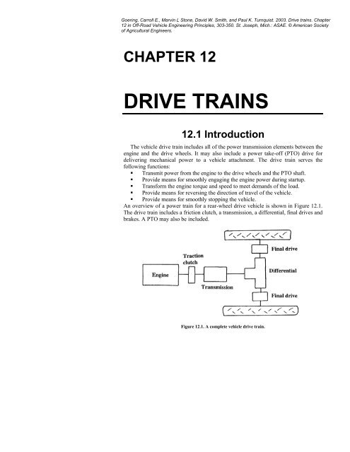
CHAPTER 12 DRIVE TRAINS 12.1 Introduction
CHAPTER 12 DRIVE TRAINS 12.1 Introduction
CHAPTER 12 DRIVE TRAINS 12.1 Introduction
- No tags were found...

Create successful ePaper yourself
Turn your PDF publications into a flip-book with our unique Google optimized e-Paper software.
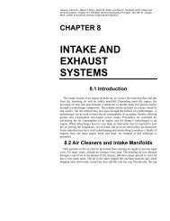
OFF-ROAD VEHICLE ENGINEERING PRINCIPLES 305Clutch actuating mechanisms could be mechanical linkages. Typically, actuation ofa traction clutch would be through a pedal operated by the operator’s left foot. Onsome vehicles, the foot pedal operates a master hydraulic cylinder that, in turn, drivesa slave cylinder to move the disengaging collar, thus eliminating the mechanicallinkage.The clutch illustrated in Figure <strong>12</strong>.2 is a dry clutch suitable for vehicles of low tomoderate power output. In heavier-duty vehicles, a dry clutch may not be able todissipate the heat that is generated during clutch engagement and a wet clutch is used.The wet clutch shown in Figure <strong>12</strong>.3 is a dual clutch. The clutch on the right, with twoclutch disks (No. 10 in the figure) interspersed between three pressure plates, is thetraction clutch. The clutch on the left, also with two clutch disks (No. 7) interspersedbetween three pressure plates, controls the PTO. The inner shaft (No. 34) goes to thetransmission, while the outer shaft drives the PTO shaft (No. 33) through an idler gear(No. 31). Multiple disks are required because the oil cooling reduces the coefficient offriction between the disks and pressure plates. A hydraulic actuator (No. 4) pushesclutch levers (No. 5) to engage the traction clutch. Another hydraulic actuator (No. 28)pushes clutch levers (No. 25) to engage the PTO clutch. In this wet clutch, a foot pedaloperates a valve that directs oil into or allows release of oil from the actuating cylinderof the traction clutch. Usually, the clutch valve that regulates oil flow into or out of theactuating cylinder of the PTO clutch is controlled by a hand lever.The torque-transmitting capacity of a clutch can be calculated byT = f F r n(<strong>12</strong>.1)ccwhereT c = torque capacity, N.mf = coefficient of frictionF c = clamping force provided by clutch springs, kNr m = mean radius of clutch, mmn s = number of torque-transmitting surfaces = 2 times the number of disks.The torque capacity of the clutch should be two to three times the peak torque of theengine to allow some reserve capacity. The torque reserve allows quick lockup andminimum slippage after lockup when the clutch is engaged. The mean radius of theclutch isrm3msDo− Di= (<strong>12</strong>.2)2 23(D − D )owhereD o = outer diameter of clutch disks, mmD i = inner diameter of clutch disks, mmCoefficients of friction of some common clutch disk materials are given in Table<strong>12</strong>.1. There are two classes of materials, depending on whether a dry clutch or a wetclutch is used.3i
306 <strong>CHAPTER</strong> <strong>12</strong> <strong>DRIVE</strong> <strong>TRAINS</strong>Figure <strong>12</strong>.3. A hydraulically operated wet clutch. (Courtesy of Deere and Co.)
OFF-ROAD VEHICLE ENGINEERING PRINCIPLES 307MaterialTable <strong>12</strong>.1. Design data for clutches and brakes.FrictionCoefficient,fMax. FacingPressure,N/mm 2Cooling OilFlow,L/s/m 2Max. EnergyRate,W/mm 2Max. BulkTemperature,° CDry operationOrganic 0.2 – 0.3 0.1 – 0.3 Dry 0.5 – 0.8 150Cerametallic 0.3 – 0.4 0.7 – 0.9 Dry 0.8 – 2.3 200 – 250Wet operationPaper 0.09 – 0.13 0.8 – 2.5 6 – 30 0.8 – 1.2 230 – 280Molded 0.08 – 0.10 1.5 – 2.5 2.5 – 30 1.0 – 1.2 230 – 280Filled fluorocarbon 0.08 – 0.10 1.5 – 2.5 2.5 – <strong>12</strong> 1.0 – 3.0 250 – 300Sintered metallic 0.04 – 0.09 1.2 – 3.5 2.5 – <strong>12</strong> 1.0 – 2.0 300The heat generated in slippage can be estimated asπQ = (TsNsts)30(<strong>12</strong>.3)whereQ = heat generated, JT s = average torque being transmitted while clutch is slipping, N.mN s = maximum speed of pressure plate relative to clutch disks, rpmt s = duration of slip, sThe temperature rise can be estimated byθ − θoQ=m Ccp(<strong>12</strong>.4)whereθ = clutch temperature after engagement, °Cθ o = clutch temperature before engagement, °Cm c = mass of heat absorbing parts of clutch, kgC p = specific heat of heat absorbing elements, J/(kg °C)Nonmetallic friction disks will not absorb much heat; therefore the moving metalparts of the clutch must provide the heat absorption. The equation for calculating thespecific rate of heat generation is a modification of Equation <strong>12</strong>.3:Er2πTsN=60 AwhereE r = specific rate of heat generation, W/mm 2A c = combined area of all friction surfaces, mm 2cs(<strong>12</strong>.5)
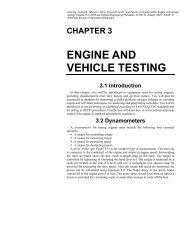
308 <strong>CHAPTER</strong> <strong>12</strong> <strong>DRIVE</strong> <strong>TRAINS</strong>It is important to limit the rate of heat generation in a clutch. The specific rate of heatgeneration must be less than the maximum energy rate and the clutch temperaturemust be less than the maximum bulk temperature given in Table <strong>12</strong>.1 for the materialused in the clutch.<strong>12</strong>.2.2 BrakesOriginally, drum brakes were used to stop vehicles. Disk brakes have become morepopular in recent years. Disk brakes include a disk that is attached to the rotating axleof each wheel and a brake caliper that is attached to the non-rotating axle housing.Each caliper contains a pair of brake pads that straddle the brake disk. When thebrakes are actuated, the caliper squeezes the brake pads together and forces them togrip the rotating disk. Equation <strong>12</strong>.1 can be used to calculate the stopping torque. Aswith clutches, the brake design should provide for a torque reserve of two to three. Theeffective radius, r m , is the radial distance from the center of the axle to the center of thebrake pads. Equation <strong>12</strong>.3 can be used to calculate the heat generated as the brakeshoes absorb energy in bringing the vehicle to a halt. Equation <strong>12</strong>.4 can be used tocalculate the temperature rise and Equation <strong>12</strong>.5 can be used to calculate the specificrate of heat generation in the braking process. As with a clutch, the specific rate ofheat generation must be within the limit given in Table <strong>12</strong>.1 for the material used inthe brake pads.<strong>12</strong>.3 Transmissions and Load MatchingA transmission serves a number of functions. It provides for forward travel, reversetravel, or neutral. Also, it provides a means for transforming the engine torque andspeed to levels that are suitable for the external load on the vehicle. Figure <strong>12</strong>.4illustrates the use of the transmission to transform torque and speed. The torque andspeed of the engine are transformed to those at the vehicle axles through use of thefollowing equations:NNA=Gept(<strong>12</strong>.6)andT = G e T(<strong>12</strong>.7)AwhereN e = engine speed, rpmN A = axle speed, rpmT e = engine torque, N.mT A = axle torque, N.me pt = e T e D e FD = power train efficiency, product of transmission (e T ),differential (e D ), and final drive (e FD )efficienciesG pt = G T G D G FD = power train gear (speed) ratio, product of speed ratiosof transmission (G T ), differential (G D ), and final drive (G FD )ptpte
OFF-ROAD VEHICLE ENGINEERING PRINCIPLES 309Figure <strong>12</strong>.4. Torque-speed curves of (a) an engine and (b) vehicle rear axle.The final drive ratio in some vehicles is 1.0, i.e., the drive axles are connecteddirectly to the differential side gears (G D = 1.0). Usually, G D and G FD arenonadjustable in a vehicle, but the operator can change G T by shifting thetransmission. The power train transforms the engine torque-speed curve to a series oftorque-speed curves at the axles, with one axle curve for each speed ratio, G T , in thetransmission. Figure <strong>12</strong>.4b shows the axle torque-speed curves for a four-speed
310 <strong>CHAPTER</strong> <strong>12</strong> <strong>DRIVE</strong> <strong>TRAINS</strong>transmission. When the transmission is in a specific gear, the axles can operate onlyon the torque-speed curve for that gear (if the engine is at the maximum governorsetting) or at points below the curve (if the engine is at reduced governor setting). Thedashed line on Figure <strong>12</strong>.4b is a constant power line; it shows the combinations oftorque and speed that would be attainable if the engine was kept at governor'smaximum at all times. The cross-hatched areas show axle torque and speedcombinations for which engine power is sufficient but which cannot be reachedbecause the transmission lacks a suitable gear ratio for those areas. The vehicle is mostproductive when it operates on the dashed constant-power line. Two approaches areused in transmission design to improve the efficiency and productivity of vehicles.The first is to increase the number of available speed ratios, thereby reducing the areasthat are cross-hatched. The second is to design for rapid shifting so that lessmomentum is lost during a gear shift.<strong>12</strong>.4 Types of TransmissionsThe following list of types of transmissions is in order of increasing vehicleproductivity and convenience in changing transmission speed ratios:1. Sliding gear2. Constant-mesh3. Synchromesh4. Power-shift5. Continuously Variable Transmission (CVT)6. HydrokineticA CVT or a hydrokinetic drive may be integrated into a gear-type transmission.<strong>12</strong>.5 Gear DesignMost transmissions rely on gears to transmit power. Gear design is a specializedactivity. Manufacturers generally have access to computer software that encompassesgear design theory and, with suitable inputs from the designer, can produce output thatdrives numerically controlled machines to actually manufacture the gears. However,many manufacturers still use hobs and shavers to produce gears based on thecomputer-aided designs. Because of the specialized nature of gear design, only a briefoverview will be given to acquaint the reader with the terminology and basicconsiderations in gear design.Spur gears or helical gears are meshed from parallel shafts. The teeth on spur gearsare parallel to the axis of rotation, while helical gear teeth are at an angle to the axis ofrotation. Helical gears gradually transfer the load from one tooth to the next and aremuch quieter than spur gears.Gear teeth have an involute profile. The profile is one that is generated by a pointon a string as the string unwraps from a cylinder (see Figure <strong>12</strong>.5). A perfect involuteprofile would transmit constant rotational velocity. However, imperfections inmachining and in heat treating cause profile errors, which result in impact stresses andnoise. Some of the details and terminology of involute gears are illustrated in Figures<strong>12</strong>.6 and <strong>12</strong>.7.
OFF-ROAD VEHICLE ENGINEERING PRINCIPLES 311Figure <strong>12</strong>.5. Involute gear tooth profile. (From Browning, 1978.)Bevel gears connect shafts with intersecting axes. While the most commonapplication is for perpendicular shafts, there are applications for bevel gears in whichthe shafts form angles less than or greater than 90°. Straight bevel gears are the bevelgear equivalent of spur gears. Thus, they transfer load abruptly from tooth to tooth andare noisy. The curved teeth on spiral bevel gears transfer load gradually from tooth totooth and thus are much quieter than straight bevel gears. Hypoid bevel gears aresimilar to spiral bevel gears, except that the shafts do not intersect. Hypoid bevel gearsare stronger and can be used for greater speed ratios than the spiral bevel gear, but thegreater tooth sliding of hypoid bevel gears make them less efficient than spiral bevelgears.
3<strong>12</strong> <strong>CHAPTER</strong> <strong>12</strong> <strong>DRIVE</strong> <strong>TRAINS</strong>Figure <strong>12</strong>.6. Gear tooth pressure angle.Designing a gear mesh requires iteration to adjust the shaft center distance, thenumbers of teeth in both gears, the gear width, pressure angle, and other factors. Suchiteration is best accomplished using computer software. The gear mesh is optimizedwhen tooth bending and surface compressive stresses are near the maximum allowableunless reduced to reduce noise. Usually, the desired gear ratio is known. When thenominal tooth size (pitch) and center distance have been selected, the pitch diameterand number of teeth can be calculated. For spur gears and helical gears, the pitchdiameter of the pinion (the smaller gear) is given by
OFF-ROAD VEHICLE ENGINEERING PRINCIPLES 313Figure <strong>12</strong>.7. Gear tooth terminology.DDpc2=1+G(<strong>12</strong>.8)whereD p = pitch diameter of pinion, mmD c = shaft center distance, mmG = speed ratio, greater than oneThe same equation can be used to calculate the pitch diameter of the larger gear if G isreplaced by 1/G. The following equation gives the relationship between the gearmodule, the pitch diameter and the number of teeth on the gear:wherem = tooth size module, mmD G = pitch diameter of the gearn = number of teeth on the gearDGm =n(<strong>12</strong>.9)
314 <strong>CHAPTER</strong> <strong>12</strong> <strong>DRIVE</strong> <strong>TRAINS</strong>For helical gears, m is the module in the transverse plane and is related to the normalor cutter module bymnm = cos ψ(<strong>12</strong>.10)wherem n = normal or cutter module, mmψ = the helix angleTypical tooth modules for gears in a vehicle drive train are as follows:Transmission gears4 to 5 mmPower-shift planetary gears 1.5 to 3.5 mmSpiral bevel gears8 to <strong>12</strong> mmFinal drive gears5 to 7 mmGear cutters of nominal size and pressure angle are usually used, but centerdistances and tooth numbers are often chosen such that the nominal pitch diameters donot touch, as shown in Figure <strong>12</strong>.5. Thus, the working pitch diameter is different fromthe nominal pitch diameter used in Equation <strong>12</strong>.9. The corresponding workingpressure angle is given byφw= cos−1m(n1+ n ) cos φ22 Dct(<strong>12</strong>.11)whereφ w = working pressure anglem = gear module in the transverse plane, from Equation <strong>12</strong>.10n 1 , n 2 = numbers of teeth on the gears in the meshφ t = the transverse pressure angle = tan -1 (tan φ n /cos ψ)φ n = nominal or pressure cutter angleGears in many off-road vehicles require high-quality materials and manufacturingto withstand the very high stresses encountered in service. The tooth surfaces must bevery hard to withstand the compressive interfacial stresses, but must also be fatigueresistantto endure the cyclic loading as the teeth move into and out of mesh. Therequired properties are obtained by using a medium carbon or alloy steel and thenquenching or induction hardening to obtain a very hard surface with a fatigue-resistantcore. A surface hardness of Rockwell C 56 to 60 is generally specified, which gives ayield strength of at least 2000 MPa. The gear teeth must be designed for stressesbelow the endurance limit for fatigue, because a gear running at only 1000 rpm can gothrough 1,000,000 stress cycles in only 20 hours.Gears must be lubricated to reduce friction and provide cooling. An extremepressure additive must be used to prevent surface welding. The extreme interfacialpressures prevent hydrodynamic lubrication. Instead, elastohydrodynamic lubricationoccurs in which the oil viscosity increases so much that the lubricant resembles coldasphalt. Such lubrication allows transmission gears to mesh with very little indicationof mating surface contact. However, spiral bevel gears generally show a high polish,while final drive gears show some contact and wear.
OFF-ROAD VEHICLE ENGINEERING PRINCIPLES 315The sliding contact between gear teeth is an important cause of power loss intransmissions. Power losses are typically 1% to 2% for external gears and 0.5% to1.5% for internal gears. Thus, an average efficiency of 98.5% for external gear setsand 99% for internal gear sets is often used.<strong>12</strong>.6 Sliding Gear, Constant-Mesh,and Synchromesh TransmissionsThe first four types of transmissions listed in Section <strong>12</strong>.4 are all manually shiftedtransmissions. The first three types include two or more parallel shafts, as shown inFigure <strong>12</strong>.8. The gears can be permanently fixed on one of the shafts. In the slidinggear transmission, the moveable gears are spline-connected to their shaft. Themoveable gears are slid axially to move out of or into mesh with fixed gears on theother shaft. Meshing of spur gears, such as those shown in Figure <strong>12</strong>.8, is noisy. Noisecan be reduced by designing a stiff housing with curved surfaces to minimize noiseamplification, and by providing uniform and low-stiffness gear teeth to minimizecyclic force generation. Helical-cut gears, such as those used in constant-meshtransmissions, are quieter but cannot be slid axially. Thus, the gears are kept inconstant-mesh with mating gears on the other shaft, but one set of gears (those on thelower shaft in Figure <strong>12</strong>.8) are free to rotate on their shaft. Collars (or slidingcouplings) are spline-connected to their shaft and can be slid forward or backward tolatch to an adjacent gear. In Figure <strong>12</strong>.8, for example, sliding coupling number 1forward would latch it to the 55-tooth gear, and power would flow from the main shaftthrough the meshing of the 28-tooth gear with the 55-tooth gear. When gears withfixed centers are meshed, the speed ratio can be calculated by remembering that theproduct of the number of gear teeth times the gear rotational speed is constant for bothgears in the mesh. Thus, the speed ratio of the mesh is given byinGm= =NoutwhereG m = speed ratio of the meshN in = speed of the input gearN out = speed of the output gearn in = number of teeth on the input gearn out = number of teeth on the output gearThe torque ratio for the mesh isoutinN= ewhereT in , T out = input and output torques, respectivelye m = efficiency of the meshTTmGnnmoutin(<strong>12</strong>.<strong>12</strong>)(<strong>12</strong>.13)
316 <strong>CHAPTER</strong> <strong>12</strong> <strong>DRIVE</strong> <strong>TRAINS</strong>Figure <strong>12</strong>.8. A constant-mesh transmission.
OFF-ROAD VEHICLE ENGINEERING PRINCIPLES 317Figure <strong>12</strong>.9. A transmission synchronizer.The sliding gear and constant-mesh transmissions are unsynchronized and shiftingis slow. For example, consider shifting the transmission in Figure <strong>12</strong>.8 from first tosecond gear by moving the number 1 sliding coupling forward to unlatch from the 61-tooth gear and to latch with the 55-tooth gear. The operator could easily slide thecoupling forward to unlatch from the 61-tooth gear after releasing the clutch.However, the main shaft would immediately begin decelerating because it hasinsufficient momentum torque to overcome bearing friction. The main countershaft isstill connected to the drive wheels through the drive train and vehicle momentum willkeep that shaft turning with little loss of speed. Thus, the coupling will be rotating at adifferent speed than the 55-tooth gear and it will be difficult to latch them together. Italmost always is necessary to bring the vehicle to a complete stop to complete theshift. The synchromesh transmission overcomes this loss of productivity by replacingthe sliding couplings with synchronizers.
318 <strong>CHAPTER</strong> <strong>12</strong> <strong>DRIVE</strong> <strong>TRAINS</strong>The principle of a synchronizer is shown in Figure <strong>12</strong>.9. The synchronizer is splineconnectedto the shaft, while the adjacent gears rotate freely on the shaft. Note the slotin the synchronizer sleeve for insertion of a shifting fork. When the operator beginssliding the sleeve toward the adjacent gear, conical friction surfaces come into contactto equalize the speeds of the sleeve and the gear. The sleeve is then moved further tolatch to the gear before the clutch is re-engaged. The friction surfaces need nottransmit high torque, because latching occurs before the traction clutch is re-engaged.<strong>12</strong>.7 Power-Shift TransmissionsPower-shift transmissions can be shifted with virtually no interruption in powerflow to the drive wheels. Hydraulically operated clutches and brakes within thetransmission are used to accomplish shifting, so there is no need for a traction clutch.The two principal types of power-shift transmissions are the countershaft type and theplanetary type.<strong>12</strong>.7.1 Countershaft-Type, Power-Shift TransmissionsFigure <strong>12</strong>.10a shows a countershaft-type transmission used as a high-low unit,while Figure <strong>12</strong>.10b shows a shuttle (reversing) transmission. In both cases, the inputshaft drives the drum on the right end of the input shaft. The left drum in Figure<strong>12</strong>.10a is driven through gear meshes G-1 to G-2 and G-3 to G-4; thus, depending onthe numbers of teeth on the gears, the left drum can turn faster or slower than the rightdrum. The unit in Figure <strong>12</strong>.10a is for an underdrive, so the left drum turns slowerthan the right drum. The disks in both clutches are spline-connected to the outputshaft. When the left clutch is engaged, as shown in Figure <strong>12</strong>.10a, power flowsthrough the two gear meshes and the left clutch, and the output shaft turns slower thanthe input shaft. The speed ratio can be calculated when the numbers of teeth on thegears is known. When the right clutch is engaged, the output shaft turns at the samespeed as the input shaft. When both clutches are disengaged, the transmission is inneutral. When both clutches are engaged, the transmission is locked, as for a parkingbrake. Figure <strong>12</strong>.10b works on the same principle, except that an extra gear (G-5) hasbeen added to cause the left drum to rotate opposite in direction to the right drum.Thus, the vehicle reverses in direction when the left clutch is engaged.Power-shift transmissions are subject to the same power losses per gear mesh aswas discussed in Section <strong>12</strong>.5. In addition, when hydraulic power is used to engage ordisengage the clutches and brakes in a power-shift transmission, that hydraulic powercan be charged as a power loss to the transmission. Consequently, power-shifttransmissions offer more convenient speed changing than manual-shift transmissions,but also absorb more of the input power than manual-shift transmissions.<strong>12</strong>.7.2 Planetary Gear SetsA planetary gear set is illustrated in Figure <strong>12</strong>.11. In an analogy to our solarsystem, the planet gears rotate about a sun gear while being carried on a planetcarrier. The planets are also in mesh with a ring gear. The planetary gear set cannottransmit power unless two elements are locked together or one of the elements is held
OFF-ROAD VEHICLE ENGINEERING PRINCIPLES 319Figure <strong>12</strong>.10. Countershaft-type, power-shift transmissions for (a) high-low and (b) reversing.
320 <strong>CHAPTER</strong> <strong>12</strong> <strong>DRIVE</strong> <strong>TRAINS</strong>SUN GEARPLANETPINIONSRINGGEARFigure <strong>12</strong>.11. A planetary gear set.PLANET PINIONCARRIERstationary. Planetary gear sets are more compact than simple reduction gears becausethe gear loads are shared equally by three planet gears. Planetary gear sets help tomaintain continuous power flow during shifting of a power-shift transmission becausethe input and output planetary members cannot change speeds without accelerating athird member, which provides a reaction torque and transmittal of power through theplanetary system.Engineers have many techniques to determine the speed ratio of a planetary gearset. Use the technique with which you are most comfortable. The following equationalso gives speed ratios of the planetary gear set in Figure <strong>12</strong>.11:n s N s = (n s + n r )N pc – n r N r (<strong>12</strong>.14)wheren = number of gear teethN = rotational speed, rpmr, s, pc = subscripts referring to the ring gear, sun gear and planet carrier,respectively.
OFF-ROAD VEHICLE ENGINEERING PRINCIPLES 321The speed ratio of a transmission is the input speed divided by the output speed(Equation <strong>12</strong>.6). A frequent application of the planetary gear set of Figure <strong>12</strong>.11 is tohold the ring gear stationary while putting power into the sun gear and taking powerout on the planet carrier. The speed ratio of such a drive can be calculated fromEquation <strong>12</strong>.14 by setting N r = 0 and solving for N s /N pc . The result isGtN=Nspcn=s+ nnsr(<strong>12</strong>.15)Another alternative is to drive the sun gear and take power out from the ring gearwhile holding the planet carrier stationary. Note that when the resulting equation issolved for N s /N r the result is negative, indicating that the ring gear turns opposite indirection to the sun gear. Conversely, a positive ratio indicates the input and outputelements rotate in the same direction.The efficiency of a planetary gear set can be analyzed using engineering principles.To illustrate, we will determine the efficiency of the planetary gear set of Figure <strong>12</strong>.11when the input is to the sun gear, the output is from the planet carrier, and the ringgear is being held. We start with the basic definition of efficiency as applied to thegear set, i.e.,power out TpcNet= =power in T Nspcs(<strong>12</strong>.16)wheree t = efficiency of the transmissionT pc , T s = torque of planet carrier and sun gear, N.mThe speed ratio, N s /N pc , is given by Equation <strong>12</strong>.15. The torque ratio can becalculated by following the power through the gear set as if the planet carrier wasfixed and noting torque reductions due to the inefficiencies in the meshes encountered.Thus, the planet torque isnpTp= espTsn(<strong>12</strong>.17)where e sp = efficiency of the sun to planet mesh.Likewise, the ring gear torque isnTr=nsrpeprTp(<strong>12</strong>.18)where e pr = efficiency of the planet to ring gear mesh.Next, from a static equilibrium of the external torques on the planetary gear set, wenote that the torques on the sun and ring gears are in the same direction and oppositeto the torque on the planet gear, resulting inT = T + T(<strong>12</strong>.19)pcsr
322 <strong>CHAPTER</strong> <strong>12</strong> <strong>DRIVE</strong> <strong>TRAINS</strong>Finally, combining Equations <strong>12</strong>.15 through <strong>12</strong>.19 and simplifying gives thefollowing equation for the efficiency, e t , of the planetary gear set when input is to thesun, output is from the planet carrier, and the ring gear is being held:e1+eersp prnst=n(<strong>12</strong>.20)r1+nThe same principles can be applied to calculate the efficiencies of other planetary geardrives.Certain principles must be observed if a planetary gear set is to assemble andfunction properly. The number of teeth on the planet gears is not important as long asthe tooth profile will mesh properly with the teeth of the sun and ring gears. Note thefollowing relationship:ns+ nγprsn= Integer(<strong>12</strong>.21)where γ p = number of equally spaced planet gears.Compound planetary gear transmissions, to be discussed in the next section, aremuch more complex except when the number of teeth in all the sun and ring gears isdivisible by the number of planet gears. Simple inspection will show that properassembly will be obtained when this is the case. There may be other combinations thatwill assemble properly, but the correct indexing of the planet gears must be found bytrial and error methods as discussed by Meyers (1965, in Suggested Readings andReferences).<strong>12</strong>.7.3 Compound Planetary TransmissionsThe planet carrier in a compound planetary transmission carries two sets of planetsof differing size: one set meshes with a sun gear and the other meshes with a ring gearthat is offset from the sun gear. Compound planetary gear sets may also include twosun gears and/or two ring gears. The transmission illustrated in Figure <strong>12</strong>.<strong>12</strong> includes acompound planetary in the input section of Figure <strong>12</strong>.<strong>12</strong>a, another in the center sectionof Figure <strong>12</strong>.<strong>12</strong>b, and a third in the output section of Figure <strong>12</strong>.<strong>12</strong>c. Taken together,the three sections form a full power-shift transmission. Numerous power-shifttransmissions have been and are available on the market. The transmission in Figure<strong>12</strong>.<strong>12</strong> was included only to illustrate the calculation of speed ratios and the possibilityof gear duplication.The input section of Figure <strong>12</strong>.<strong>12</strong>a has two concentric output shafts. The inner shaftis driven when clutch C 1 is engaged, while the outer shaft is driven when clutch C 2 isengaged. Connected to outer shaft C 2 are the disk portion of clutch C Lo and the planetcarrier of a compound planetary gear set. The smaller planet gears roll in a ring gearthat drives the output shaft of the compound planetary gear set. The larger planets rollon a sun gear that is connected to the high-low drum. When clutch C Lo is engaged, the
OFF-ROAD VEHICLE ENGINEERING PRINCIPLES 323Figure <strong>12</strong>.<strong>12</strong>. A full power-shift transmission.sun gear is forced to rotate at the same speed as the planet carrier, thus the planet gearscannot rotate on their axes, the ring gear must rotate at the same speed as the planetcarrier, and the output ring gear turns at the same speed as the engine. When brake B Hiis engaged, the sun gear is held stationary, the larger planet gears roll on the sun gear,and the ring gear is driven by the smaller planet gears. Application of the principlesdiscussed in Section <strong>12</strong>.7.2 leads to the following equation for calculating the speedratio of a compound planetary drive:
324 <strong>CHAPTER</strong> <strong>12</strong> <strong>DRIVE</strong> <strong>TRAINS</strong>N nss= Npc(ns+ nrnnpspr) − N nrrnnpspr(<strong>12</strong>.22)wheren ps = number of teeth on each planet gear in mesh with the sun gearn pr = number of teeth on each planet gear in mesh with the ring gearIn applying Equation <strong>12</strong>.22 to the input section of Figure <strong>12</strong>.<strong>12</strong> when C 2 and B Hiare engaged, notice that N s = 0 because the sun gear is held stationary by engagingbrake B Hi . Then Equation <strong>12</strong>.22 reduces to a simpler equation which can be solved forthe speed ratio of the input section, G i = N pc /N r . When clutch C 2 is engaged, the outershaft (C 2 ) is driven at engine speed when clutch C Lo is engaged, but with speed ratioG i when brake B Hi is engaged. The inner shaft (C 1 ) is driven at engine speed whenclutch C 1 is engaged.The center section of the transmission (Figure <strong>12</strong>.<strong>12</strong>b) also contains a compoundplanetary. Notice that this compound planetary contains two sun gears and two ringgears in addition to a planet carrier with two sets of planet gears. The input is throughthe sun gear on the right if clutch C 1 is engaged, or through the sun gear on the left ifclutch C 2 is engaged. The ring gear on the right can be held stationary by engagingbrake B 2 , or the ring gear on the left can be held by engaging brake B 1 . Output isalways through the planet carrier. Six different combinations are possible from thecenter section of Figure <strong>12</strong>.<strong>12</strong>b. They are:I. Drive the right sun gear and hold the right ring gear.II. Drive the left sun gear and hold the left ring gear.III. Drive the right sun gear and hold the left ring gear.IV. Drive the left sun gear and hold the right ring gear.V. Drive the right and left sun gears at the same speed.VI. Drive the right and left sun gears at different speeds.Cases I through IV involve compound planetary gear sets in which a ring gear isheld stationary. Equation <strong>12</strong>.22 can be adapted to calculate the speed ratios by settingN r = 0. In Cases I and II, Equation <strong>12</strong>.22 is used with n ps = n pr . Conversely, in Cases IIIand IV, n ps is not equal to n pr . In Case III, for example, N r = 0, n s = 21, n r = 69, n ps =26, and n pr = 16. In that case, Equation <strong>12</strong>.22 shows that the speed ratio of the centersection is G c = N s /N pc = 5.34.Cases V and VI involve driving both sun gears while both ring gears free wheel andthe planet carrier is the output. When the two sun gears are driven at the same speed,the planets cannot roll on the sun gears and the speed ratio of the center section is G c =1.0. The input and center sections must work together when both sun gears are drivenat different speeds. A kinematic analysis shows the combined ratio for the twosections can be calculated using the following equation:G GiNn1−nfsnnpsssss pfc= =npcfsn(<strong>12</strong>.23)Nps1−Gfsnssnpf
OFF-ROAD VEHICLE ENGINEERING PRINCIPLES 325whereG i G c = combined speed ratioN ss = speed of slower sun gear in rpmG fs = N fs /N ss = ratio, faster sun to slower sunn fs = number of teeth on faster rotating sun gearn ss = number of teeth on slower rotating sun gearn pf = number of teeth on planet in mesh with faster sun gearn ps = number of teeth on planet in mesh with slower sun gearIf brake B Hi is engaged (Case VI), the left sun is driven faster than the sun on the rightand G fs is greater than one.Combining the transmission sections of Figures <strong>12</strong>.<strong>12</strong>a and <strong>12</strong>.<strong>12</strong>b provides a totalof eight possible speed ratios. There are two ratios each for Cases II and IV(depending on whether clutch C Lo or brake B Hi is engaged) and one ratio for each ofthe other four cases. Up to this point, no reverse has been provided.The output section in Figure <strong>12</strong>.<strong>12</strong>c is always driven by the planet carrier. Unlikethe previous compound planetary gear sets, two sets of planet gears on the carrier arecarried on separate shafts arranged such that one set of planet gears meshes with theother. The larger set of planet gears on the right roll in a ring gear and on the right sungear, as in a standard planetary gear set. The smaller set of planet gears mesh with thelarger planets and also with the sun gear on the left. The output shaft is connected tothe sun gear on the left. The right sun gear is connected to a drum to which clutch C 3and brake B 4 are attached. In direct drive, when clutch C 3 is engaged, the two sungears are forced to rotate at the same speed. Consequently, the output shaft is forced torotate at the same speed as the planet carrier. Overdrive is achieved by engaging brakeB 4 , thus holding the right sun gear stationary. The planet carrier forces the largerplanet gears to roll in the right sun gear, driving the smaller planet gears, which in turndrive the left sun gear in the same direction as the planet carrier.Equation <strong>12</strong>.22 does not hold for the compound planetary in the output sectionbecause the paired planet gears run on separate shafts. However, the followingequation can be used to calculate the speed ratio in overdrive:Npc nslGo= =(<strong>12</strong>.24)Nslnsl+ nsrwhereG o = speed ratio of output sectionN sl = speed of sun gear on the left in rpmn sl = number of teeth on sun gear on the leftn sr = number of teeth on sun gear on the rightWhen brake B 3 is engaged, the ring gear is held stationary and the planet carrierforces the large planet gears to roll in the stationary ring gear. The larger planets drivethe smaller planets that, in turn, drive the sun gear on the left. Again, Equation <strong>12</strong>.22does not hold but the following equation can be used to calculate the speed ratio:GoN=Npcslnsl=n − nslr(<strong>12</strong>.25)
326 <strong>CHAPTER</strong> <strong>12</strong> <strong>DRIVE</strong> <strong>TRAINS</strong>In the usual case, n r > n sl , thus G o is negative, and the output direction is oppositethe input direction, i.e., the vehicle is in reverse.In the output section, engaging brake B 3 provides eight possible reverse speeds, onefor each of the eight possible speeds of the planet carrier of the output section.Depending on whether clutch C 3 or brake B 4 are engaged, two possible ratios areprovided for each of the eight possible speeds of the planet carrier for a total of sixteenpossible forward speeds for the entire transmission. Table <strong>12</strong>.2 summarizes the use ofthe transmission in Figure <strong>12</strong>.<strong>12</strong> to provide a power-shift transmission with 15forward speeds and four reverse speeds. The manufacturer decided that only four ofthe possible eight reverse speeds were needed in the transmission. Also, one of the 16possible forward speeds was not used because it nearly duplicated 5th gear.Transmission designers strive to avoid such gear duplication, but it sometimes occurs.Note that locking C3 and B4 simultaneously locks the output shaft to the transmissioncase, thus providing a vehicle parking brake. Two neutrals, NR and NF are provided toallow the vehicle to be brought to a halt before the parking brake is engaged.Calculating speed ratios for a full power-shift transmission may seem to be adaunting task, but it is simply a matter of breaking the problem down into smallersteps and then combining the results, as illustrated in Example Problem <strong>12</strong>.1.Table <strong>12</strong>.2 Element engagements and resulting speed ratios in thepower-shift transmission illustrated in Figure <strong>12</strong>.<strong>12</strong>.Gear C1 C2 C Lo B Hi B1 B2 B3 C3 B4 R t4R X X X X -1.403R X X X X -2.1<strong>12</strong>R X X * X X -3.201R X X * X X -4.58NRPark X XNF1 X X * X X 6.342 X X * X X 4.433 X X * X X 3.664 X X X X 2.925 X X X X 2.536 X X X X 2.237 X X X X 1.948 X X X X 1.699 X X X X 1.4610 X X X X 1.2911 X X X X 1.<strong>12</strong><strong>12</strong> X X X X 1.0013 X X X X 0.8114 X X X X 0.57815 X X X X 0.467Unused X X X 2.56X indicates the element is engaged for the gear indicated.X * indicates the element not needed but engaged for convenience.
OFF-ROAD VEHICLE ENGINEERING PRINCIPLES 327Example Problem <strong>12</strong>.1Calculate the speed ratio of the power-shift transmission in Figure <strong>12</strong>.<strong>12</strong> in 11thand 15th gears.SolutionClutch C 2 and brake B Hi are engaged in either 11th or 15th gears (see Table <strong>12</strong>.2).When those two elements are engaged and the input section drives only one of the sungears in the center section, the ratio isG i = N pc / N r = n r / [n r + n s n pr / n ps ] = 93 / [93 + 33 (18 / 42)] = 0.868The input section is an overdrive in this case, that is, the speed is increased in the inputsection.In 11th gear, the ring gear of the input section (Figure <strong>12</strong>.<strong>12</strong>a) drives the right sunof the center section (Figure <strong>12</strong>.<strong>12</strong>b), while the left ring gear of the center section isheld stationary. The speed ratio of the center section isG c = N s / N pc = 1 + n r n ps / [n s n pr ] = 1 + (72)(16) / [(36) (26)] = 2.23In 15th gear, the left sun gear in the center section is driven at a faster speed thanthe sun gear on the right. Equation <strong>12</strong>.23 is used to calculate the combined speed ratioof the input and center sections. Notice that, when B Hi is engaged, G fs = 1 / G i = 1 /0.868 = 1.152. Also, n fs = 36, n ss = 21, n pf = 16, and n ps = 26. Grouping these toothnumbers in the combination needed in Equation <strong>12</strong>.23 gives[(36) (26)] / [(21) (16)] = 2.788Then the combined speed ratio of the input and center sections isG i G c = [1 – 2.788] / [1 – 2.788 (1.152)] = 0.808In the output section, the planet carrier is driven, the right sun gear is heldstationary, and the left sun gear drives the output shaft. Equation <strong>12</strong>.24 can be used tocalculate the speed ratio, as follows:G o = N pc /N sl = n sl /[n sl + n sr ] = 26/[26 + 19] = 0.578The output section functions as an overdrive in this case, that is, the speed is increasedin the output section.The speed ratio for the entire transmission, G t , is the product of the speed ratios ofthe three sections. In 11th gear, the ratio of the entire transmission isIn 15th gear, the transmission ratio isG t = G i G c G o = (0.868) (2.23) (0.578) = 1.<strong>12</strong>G t = G i G c G o = (0.808) (0.578) = 0.467The transmission is an overdrive in 15th gear, that is, the output shaft rotates fasterthan the input shaft.
328 <strong>CHAPTER</strong> <strong>12</strong> <strong>DRIVE</strong> <strong>TRAINS</strong><strong>12</strong>.7.4 Electro-Hydraulic ShiftingImbedded hydraulic actuators are used to engage the various clutches and brakes inpower-shift transmissions. For some power-shift transmissions, mechanically operatedvalves are used to direct pressurized hydraulic fluid to the appropriate actuators asindicated, for example, in Table <strong>12</strong>.2. For some power-shift transmissions, solenoidvalves are used to direct the fluid. When two-state, i.e., off-on solenoid valves areused, accumulation and restriction valves are needed to smooth the shifting action.However, fluid viscosity and density changes resulting from temperature changes tendto degrade the consistency of shifting, resulting in operator discomfort and earlydriveline failures.A recent innovation, the electro-proportional pressure-reducing (EPPR) valve, wasdesigned to provide smooth, consistent shifting without the need for accumulation andrestriction valves. A cross sectional view of an EPPR valve is shown in Figure <strong>12</strong>.13.One such valve is provided for each clutch or brake in a power-shift transmission.Note the three external o-ring seals on the EPPR valve. The portion of the valve to theright of the right-most o-ring is immersed in port 1, the pump port. The portion of thevalve between the center and right-most o-rings is immersed in port 2, the clutch (orwork) port. The portion of the valve between the center and the left-most o-rings isimmersed in port 3, the tank port. A pilot operated sliding spool determines theconnectivity between the ports. Pilot operation is initiated by supplying pulse-widthmodulated(PWM) electrical current to an electrical coil in the left end of the EPPRvalve.In the de-energized mode, a bias spring at the right end of the sliding spool holdsthe spool in the left-most position illustrated in Figure <strong>12</strong>.13. Port 2 is connected toport 3 to reduce the work port pressure to near zero to keep the corresponding clutchor brake disengaged. Oil from Port 1 flows via a cross passage and central passage inthe sliding spool, through a filter screen and orifice to the open ball valve, and throughthreads on the outer edge of the spool housing to Port 3. The oil experiences somepressure drop in passing through the threads but, if the pressure in Port 3 is kept smallenough, the pressure in the area of the ball housing will be less than the 100 kPaneeded to compress the bias spring to move the sliding spool to the right.Figure <strong>12</strong>.13. An electro-proportional pressure-reducing valve. (From Harms and Guse, 2000.)
OFF-ROAD VEHICLE ENGINEERING PRINCIPLES 329Actuation of the EPPR valve begins when the duty cycle of the PWM signal to thecoil is increased, causing the steel pin to the left of the ball valve to push the valveonto its seat. The resulting pressure buildup in the pilot chamber to the right of the ballvalve overcomes the bias spring and causes the sliding spool to move to the right.With sufficient movement, the sliding spool disconnects the work port from the tankport and connects the work port to the pump port. The resulting pressure buildup in thework port engages the clutch or brake whose cylinder is connected to the work port.Note that the amount of sliding spool movement, and thus the pressure level in thework port, varies with the duty cycle of the PWM signal delivered to the coil. This isbecause the degree of openness of the ball valve varies with the force balance betweenthe hydraulic force supplied by the pressurized oil flowing through the center of thesliding spool and the electrical force supplied by the coil in moving the steel pinagainst the ball. When the duty cycle of the PWM signal reaches 100%, the ball valveis fully closed and the pressure in the pilot chamber rises to essentially the same levelas the pressure in the pump port.Each hydraulic actuator operating the clutches and brakes functions like a springreturn,single-acting cylinder. The speed of engagement is controlled by the rate ofpressure increase to the cylinder, while the speed of disengagement is controlled bythe rate of pressure decrease. Typically, about 167 kPa of pressure is required toinitiate movement of the cylinder and 230 to 330 kPa is required to reach the kiss point(the point at which the clutch or brake begins to engage). The slippage of the clutch orbrake that begins with engagement is essentially stopped when the pressure reaches 1MPa. Typically, the pressure then builds to about 2 MPa to provide for reservecapacity. If the actuating cylinder is empty when pressurization begins, significanttime can elapse before the clutch or brake engages. Thus, the conduits should bearranged to allow gravity to keep the cylinders full between actuations. Also, withcareful control, the PWM signal can be brought to 100% duty cycle for a short timebefore each actuation to allow rapid filling, but then reduced before the cylinderengages the clutch or brake. Finally, between actuations, the EPPR can keep thecylinder pressurized to a pressure just below the kiss point. When actuation is desired,the EPPR can ramp up the pressure to provide a controlled engagement of the clutchor brake. Likewise, pressure can be ramped down to provide a controlleddisengagement. Such careful control of the EPPR is accomplished by amicroprocessor. Using a small lever attached to an indicating device (a potentiometeror multi-position switch), the vehicle operator can signal the microprocessor as to adesired gear change. Upon reading the indicating device, the microprocessor consultsa table such as Table <strong>12</strong>.2 to determine which clutches and brakes are to be deenergizedto move out of the gear that is being left, and which clutches and brakes areto be energized to move into the new desired gear. The microprocessor also handlesthe rates of de-pressurization and pressurizations to cause a smooth shift.The discussion above focused on the use of EPPR valves to control a power-shifttransmission. However, the EPPR valve could also be used to control the engagementand disengagement of a hydraulically operated wet clutch.
330 <strong>CHAPTER</strong> <strong>12</strong> <strong>DRIVE</strong> <strong>TRAINS</strong><strong>12</strong>.7.5 Practical Power ShiftingA primary advantage of a full-range power-shift transmission is that speed ratioscan be changed with essentially no interruption of power. A traction clutch is notneeded for a full-range power-shift transmission. However, a clutch pedal is usuallyprovided for safety reasons. In an emergency, an operator will instinctively reach forthe clutch pedal to stop the vehicle. The clutch pedal need not operate a conventionalclutch; it could rather shift the transmission into neutral, for example, by releasingboth clutches C 1 and C 2 in Figure <strong>12</strong>.<strong>12</strong>.Full-range power-shift transmissions also have disadvantages. Considerable energyis used in the hydraulic shifting of the various clutches and brakes and because offriction in the numerous gear meshes in the transmission. The efficiency, e t , of a fullrangepower-shift transmission is typically below 85%. Such transmissions also areexpensive to manufacture.Tractor manufacturers have recognized that full-range power shifting may not beessential. As an option, they may provide part-range power shifting by placing asynchromesh transmission in series with a power-shift element. The traction clutchmust be disengaged to shift the synchromesh transmission. Power shifting within eachmanually selected gear can be accomplished without disengaging the tractor clutch.The part-range power-shift transmission is less expensive and its efficiencyapproaches 90%.<strong>12</strong>.8 Continuously VariableTransmissionsThe transmissions discussed up to this time all provided a set of discrete gear ratios.The continuously variable transmission (CVT) does not have discrete gear ratios;rather, the speed ratio is continuously variable. Considerable research anddevelopment work is underway on mechanical CVTs, and at least one is on themarket. However, the most widely available CVT for heavy-duty off-road vehicles isthe hydrostatic transmission. Figure <strong>12</strong>.14 illustrates the concept of a hydrostatictransmission. Power input is to a pump, while power output is from a hydraulic motor.QINPUTFROMENGINEP∆pMOUTPUTTODIFFERENTIALFigure <strong>12</strong>.14. A hydrostatic transmission.
OFF-ROAD VEHICLE ENGINEERING PRINCIPLES 331All hydrostatic transmissions can be classified into one of the four following types:1. Fixed-displacement pump and fixed-displacement motor2. Variable-displacement pump and fixed-displacement motor,3. Fixed-displacement pump and variable-displacement motor4. Variable-displacement pump and variable-displacement motorThe following equations govern the input-output relationships of a hydrostatictransmission. The speed relationship isandN = (emmvepvD)DThe following two equations govern the torque relationship:T = (emptemtD)DwhereN p = pump (input) speed, rpmN m = motor (output) speed, rpme pv = volumetric efficiency of pump, decimale mv = volumetric efficiency of motor, decimale pt = torque efficiency of pump, decimale mt = torque efficiency of motor, decimalD p = displacement of pump, cm 3 /revD m = displacement of motor, cm 3 /rev∆p = pressure difference across pump or motor, MPaT p = pump (input) torque, N.mT m = motor (output) torque, N.mpmmpNTpp(<strong>12</strong>.26)(<strong>12</strong>.27)emtDm∆pTm =2π(<strong>12</strong>.28)<strong>12</strong>.8.1 Type 1 Hydrostatic TransmissionsThe Type 1 hydrostatic transmission provides no possibility for changing the outputspeed unless part of the pump flow is diverted away from the motor; thus, the Type 1transmission is seldom used.<strong>12</strong>.8.2 Type 2 Hydrostatic TransmissionsThe Type 2 hydrostatic transmission provides excellent control of speed anddirection, as illustrated in Figure <strong>12</strong>.15. The pump displacement can be varied fromfull delivery in one direction to zero delivery to full delivery in the reverse direction.The Type 2 transmission has the disadvantage of being a constant torquetransmission. For maximum power-transmitting capability at full speed, thetransmission must be operated at the maximum allowable pressure difference, ∆p.
332 <strong>CHAPTER</strong> <strong>12</strong> <strong>DRIVE</strong> <strong>TRAINS</strong>When D p is reduced to reduce the output speed, the output torque is not increased, asEquation <strong>12</strong>.28 shows. Thus, the power-transmitting capability declines at lowerspeeds with the Type 2 transmission. If such a transmission were to be used on aheavy-duty vehicle, a very large pump and motor would be needed to provideadequate power at low speeds. Type 2 transmissions are commonly used in lawntractors, where power demands are limited. Heavy-duty off-road vehicles have needfor constant power transmissions. All of the gear-type transmissions discussed earlierare constant power transmissions.<strong>12</strong>.8.3 Type 3 Hydrostatic TransmissionsThe Type 3 hydrostatic transmission is a constant power transmission. D m must beincreased to reduce the output speed (Equation <strong>12</strong>.25), but increasing D m increases thetorque-transmitting capability (Equation <strong>12</strong>.26 or <strong>12</strong>.27) without increasing ∆p.However, as Figure <strong>12</strong>.16 indicates, the Type 3 transmission has poor speed-changingcharacteristics. Allowing the swash plate in the motor to cross over zero displacementwould cause a sudden reversal from maximum speed in one direction to maximumspeed in the opposite direction. Such abrupt changes cannot be permitted, so variabledisplacementmotors are designed to prevent zero displacement. The swash plate isblocked from reaching neutral, and thus the Type 3 transmission cannot providereversing of direction of travel. Also, a very large motor displacement would berequired to obtain very slow speeds.<strong>12</strong>.8.4 Practical Hydrostatic TransmissionsThe Type 4 hydrostatic transmission is used in heavy-duty applications, such as inthe transmission of a tractor. The variable-displacement pump provides excellentspeed control and reversing. When the pump displacement is reduced to reduce speed,N mFORWARDSPEEDSREVERSE MAX.DISPLACEMENTFORWARD MAX.DISPLACEMENTD pREVERSESPEEDSFigure <strong>12</strong>.15. Speed-changing characteristics of a hydrostatic transmission withvariable-displacement pump and fixed-displacement motor.
OFF-ROAD VEHICLE ENGINEERING PRINCIPLES 333NmFORWARDSPEEDSREVERSE MAX.DISPLACEMENTFORWARD MAX.DISPLACEMENTDmREVERSESPEEDSFigure <strong>12</strong>.16. Speed-changing characteristics of a hydrostatic transmission withfixed-displacement pump and variable-displacement motor.the motor displacement is simultaneously increased to provide some increase in torquecapacity. Although the torque increase at low speeds is less than for a Type 3hydrostatic transmission, it must only be sufficient to provide enough torque to reachthe traction limit of the drive wheels.Theoretically, the hydrostatic transmission of Figure <strong>12</strong>.14 could cover the entirespeed range. However, volumetric efficiencies of the pump and motor approach zeroat low speeds, while the torque efficiencies approach zero at high speeds. The powerefficiency of the entire transmission can remain high only over a limited range ofspeeds. Thus, as illustrated in Figure <strong>12</strong>.17, a hydrostatic transmission is used in serieswith a gear-type transmission in tractors. A speed range is selected by shifting the geartransmission, and the hydrostatic transmission is continually variable within thatrange. A single lever is provided to set the displacement of the pump and motorsimultaneously. Once that lever is set, the transmission behaves exactly like a geartransmission, i.e., it follows a torque-speed relationship similar to that for one of thegears in Figure <strong>12</strong>.4. Since the hydrostatic transmission is infinitely variable, however,the operator can choose from an infinite variety of ratios and thus eliminate the crosshatched areas that are inaccessible in Figure <strong>12</strong>.4. Poor power efficiency has limitedthe widespread adoption of hydrostatic transmissions in tractors. It can be shown thatthe overall power efficiency of a hydrostatic transmission is e t = e pt e pm e mv e mt . If eachof these efficiencies could be maintained at 0.95, the power efficiency of the entiretransmission would be only 0.81. However, hydrostatic transmissions have beenadopted in applications where the speed and convenience they offer in speed changingoffsets the lower power efficiency.
334 <strong>CHAPTER</strong> <strong>12</strong> <strong>DRIVE</strong> <strong>TRAINS</strong>Figure <strong>12</strong>.17. A heavy-duty hydrostatic transmission in series with a gear transmission.Some manufacturers have developed split-power transmissions in which part of thepower is transmitted hydrostatically while the majority of the power is transmittedthrough the planetary gear sets of a power-shift transmission. The hydrostatic elementallows continuous variability of speed within each of the speed ratios of the powershifttransmission. Transmitting most of the power through the planetary gear setshelps to reduce power losses in the hydrostatic unit. The result is a CVT that is moreefficient than one that uses only a hydrostatic unit.<strong>12</strong>.9 Hydrokinetic TransmissionsA schematic diagram of a hydrokinetic transmission is shown in Figure <strong>12</strong>.18. Theinput shaft drives an impeller that generates oil flow within the unit. Typically, theimpeller blades are attached to the inner edge of the transmission case, and the entirecase spins with the engine flywheel. The oil flows across a turbine that drives theoutput shaft. After leaving the turbine, the oil flows through a stator, i.e., a stationaryset of vanes that change the flow direction of the oil. The torque reaction on the statoris effectively transferred to the turbine. Without the stator, the turbine torque couldnever be greater than the impeller torque but, with the stator, the transmission is ableto provide a torque increase. Although the turbine has some effect on the impeller, thehydrokinetic transmission is more easily understood if we assume that effect isinsignificant. Then, the impeller has a definite torque-speed curve of its own, asillustrated in Figure <strong>12</strong>.19. The intersection of the impeller torque-speed curve withthat of the engine defines an operating point that remains fixed unless the operatorchanges the governor setting. Both the input speed and input torque of thetransmission remain essentially constant. Then, because the product of torque andspeed is constant across the hydrokinetic transmission, the output speed is controlledby the output torque, as indicated in the following equation:
OFF-ROAD VEHICLE ENGINEERING PRINCIPLES 335TURBINEIMPELLERSTATORINPUTSHAFTOUTPUTSHAFTFigure <strong>12</strong>.18. Schematic diagram of a hydrokinetic transmission.ENGINETORQUE, N . mT inIMPELLEROPERATINGPOINTSPEED, rev/minS inFigure <strong>12</strong>.19. Torque-speed curves for a governed engine and a hydrokinetic transmission impeller.
336 <strong>CHAPTER</strong> <strong>12</strong> <strong>DRIVE</strong> <strong>TRAINS</strong>TNin inNout=etT(<strong>12</strong>.29)outwhereN in = input speed, rpmN out = output speed, rpmT in = input torque, N.mT out = output torque, N.me t = transmission efficiencyThe hydrokinetic transmission automatically reduces output speed if the torqueload on the output shaft increases, and vice versa. Consequently, the hydrokinetictransmission has no definite speed ratio. The hydrokinetic transmission performancewould be plotted as a constant-power curve similar to the dashed line in Figure <strong>12</strong>.4.The hydrokinetic transmission can theoretically cover the entire speed range but, asFigure <strong>12</strong>.20 illustrates, the transmission becomes very inefficient when the speedratio (output speed over input speed) becomes either very low or very high. Thus, as inthe case of the hydrostatic transmission, the hydrokinetic transmission is generallyused in series with a gear-type transmission. Automatic transmissions in automobiles,trucks, busses, etc., typically include a hydrokinetic transmission in series with a twoorthree-speed, planetary type power-shift transmission. No traction clutch is provided;the gear transmission is shifted automatically to keep the hydrokinetic transmissionworking at an efficient speed ratio. On heavy-duty tractors, the hydrokineticFigure <strong>12</strong>.20. Typical performance curves for a hydrokinetic transmission.
OFF-ROAD VEHICLE ENGINEERING PRINCIPLES 337transmission is most useful when exact speed control is unnecessary, as in doingheavy tillage work. When control of travel speed is important, provision must be madefor locking out the hydrokinetic transmission to prevent the speed from changing inresponse to changes is torque load. A traction clutch is provided to allow manualshifting of the gear-type transmission when the hydrokinetic unit is locked out.<strong>12</strong>.10 Comparison of TransmissionsThe sliding gear and constant-mesh transmissions are simple and efficient intransmitting power, but are difficult to shift while the vehicle is in motion. Thesynchronizers in a synchromesh transmission improve productivity by allowing easyshifting on the go, but it is still necessary to release the traction clutch to shift gears. Afull-range, power-shift transmission can be shifted into any of its speed ratios withoutreleasing a traction clutch. Although the vehicle could be designed without a clutchpedal, one is usually included for safety reasons. In an emergency, most operators canrelease a traction clutch instinctively, but may not think fast enough to stop the tractorby using the shift lever. By allowing quicker shifting without releasing the tractionclutch, the full-range power-shift transmission provides a further productivity boostover the synchromesh transmission. As a cost saving measure, a two-speed powershiftelement is sometimes used in series with a synchromesh transmission. Powershifting without a clutch is then possible within any of the speed ranges of thesynchromesh transmission.Vehicle productivity is increased by providing more speed ratios, so that theoperator has a better chance of selecting a ratio that will perfectly match the enginetorque and speed to the needs of the load. The CVT theoretically allows the operatorto accomplish perfect load matching by providing an infinite number of speed ratios. Itremains the operator's responsibility to select the best ratio for load matching.Currently, the only CVT available for heavy-duty off-road vehicles is the hydrostatictransmission.The hydrokinetic transmission has no definite speed ratio. It automatically adjustsits output speed in response to changes in output torque. Thus, it provides automaticload matching along a constant power curve. In agricultural tractors, it is best suitedfor heavy tillage work and other operations where travel speed is not critical. If travelspeed is critical, the hydrokinetic transmission must be locked out.<strong>12</strong>.11 Resonances in Transmissionsand Computer SimulationThe shafts in transmissions undergo torsional deflection in response to appliedtorque, and therefore act as torsional springs. Some of the rotating masses in atransmission are large enough to have significant inertia. The torsional springs allowthe rotating masses to oscillate torsionally at natural frequencies that are proportionalto the square root of the torsional spring rate/inertia ratio. Torsional disturbances occurin a transmission due to engine harmonics, gear tooth meshing and other factors. The
338 <strong>CHAPTER</strong> <strong>12</strong> <strong>DRIVE</strong> <strong>TRAINS</strong>amplitude of oscillation of a simple spring-mass torsional pendulum is given by thefollowing equation:T(t)θ =2K − Jω(<strong>12</strong>.30)whereθ = amplitude of shaft oscillation, radiansT(t) = amplitude of the torque oscillations, N.mK = torsional spring rate, N.m /radianJ = moment of inertia of rotating masses, kg.m 2ω = angular frequency of the torque fluctuations, radians/sThe angular natural frequency of the system, Τ n , isω n=KJ(<strong>12</strong>.31)Note that if the driving frequency, Τ, approaches the natural frequency, Τ n , thetorsional oscillation becomes very large. In practice, there are multiple naturalfrequencies in a transmission and if any of them are approached, oscillations can buildto amplitudes that are annoying to the operator and even damaging to the transmission.The reader may consult books on vibration analysis for more extensive information onvibration.Because of the complexity of the actual vibratory system, computer simulation isusually used to identify potential vibratory problems in transmissions and to testpotential solutions. Transmission shafts are subject to torsional and bending stressesthat must be resisted without failure and computer simulation is also used for stressanalysis.<strong>12</strong>.<strong>12</strong> DifferentialsThe drive wheels of a vehicle negotiating a turn travel at different speeds, since thedrive wheel most distant from the center of turn must travel farther and faster than thedrive wheel nearest the center of turn. An exploded view of a differential is shown inFigure <strong>12</strong>.21. The transmission drives the bevel pinion, which in turn drives the ringgear to provide a speed reduction and a 90 change in shaft direction. A carrierassembly attached to the ring gear carries four differential pinion gears. Because thedifferential pinion gears are free to rotate on their shafts, the two side gears can rotateat different speeds. The speed relationships for the differential areandwhereN + NL2R= NnaveN=Gind(<strong>12</strong>.32)rGd= (<strong>12</strong>.33)nbp
OFF-ROAD VEHICLE ENGINEERING PRINCIPLES 339Figure <strong>12</strong>.21. An exploded view of a differential.
340 <strong>CHAPTER</strong> <strong>12</strong> <strong>DRIVE</strong> <strong>TRAINS</strong>N L = speed of left side gear, rpmN R = speed of right side gear, rpmG d = speed ratio of differentialn bp = number of teeth on bevel pinionn r = number of teeth on ring gearTypically, G d is in the range between 2.5 and 3.5 for differentials. The powerrelationship for the differential isT N + T N = eLLRRdTinNin(<strong>12</strong>.34)whereT L = torque in left side gear, N.mT R = torque in right side gear, N.me d = efficiency of differentialConsider any one of the differential pinion gears. Assuming zero bearing frictionon the differential pinion shaft, the peripheral force applied by the left side gear mustequal the peripheral force applied by the right side gear, since the differential pinioncannot sustain any difference in these two peripheral forces. The peripheral forces onthe differential pinion are equal to those on the side gears and, since the two side gearshave the same radius, they must also transmit the same torque. Thus, the law ofdifferentials is that the two side gears must transmit equal torques. Then, since T L =T R , Equation <strong>12</strong>.34 reduces toeTL = TR=dGd2Tin(<strong>12</strong>.35)The factor of 2 appears in the denominator because the ring gear torque is split, withhalf going to the left axle and half to the right.A differential is needed for turning, but it degrades vehicle performance in twoways. First, the torque in either side gear is limited by the traction that can bedeveloped by the attached wheel. If one driving wheel is on a sheet of ice, forexample, virtually no torque can develop in the corresponding side gear. Thus, themaximum torque transmitted through either axle is limited to the torque that can besupported by the wheel with the poorest traction. Secondly, in dividing the inputpower between the two axles, the differential routes most of the power to the axle withthe poorest traction. Since the torque is equal in both axles, the power divides inaccordance with the axle speeds. The differential allows the wheel with the pooresttraction to rotate faster and thus transmit more than half the input power. Since the twodrive wheels are attached to the same vehicle and thus must translate at the samespeed, any difference in power transmission between the wheel with the pooresttraction and the wheel with the best traction is lost in wheel slippage.A differential lock improves vehicle performance by locking one of the side gearsto the carrier or ring gear. Then both axles are forced to rotate at the same speed. Thedifferential pinions are no longer free to rotate on their shafts, and thus the torquesneed no longer be equal in the two side gears. Equation <strong>12</strong>.34 still holds, but now thespeeds of the two side gears are equal. Thus, the power divides between the two axles
344 <strong>CHAPTER</strong> <strong>12</strong> <strong>DRIVE</strong> <strong>TRAINS</strong>Figure <strong>12</strong>.25. The three types of PTO shafts.Three different arrangements have been standardized for delivering engine powerto the PTO drive. They are:• Transmission-driven PTO• Continuous-running PTO• Independent PTOAs the name implies, the first type of PTO is driven from the transmission. Thus,disengaging the traction clutch interrupts power flow to the drive wheels and to thePTO shaft. Because it is sometimes inconvenient to stop the PTO every time thetraction clutch is disengaged, the continuous-running PTO was developed. It has twoseparate clutches, but both are controlled by the same foot pedal. Initial movement ofthe pedal releases the traction clutch, and further movement releases the PTO clutch.Most new tractors now have an independent PTO, in which a hand lever or switchdisengages a separate (from the traction clutch) PTO clutch.<strong>12</strong>.16 SummaryThe power train of a vehicle includes the traction clutch, transmission, anddifferential. If the vehicle is a tractor, the power train may also include final drives anda PTO drive. The power train serves the functions of transmitting power to the drivewheels and PTO shaft, disconnecting power, reversing directions, and transformingthe engine torque and speed to meet demands of the load. In skid-steer vehicles, thepower train also accomplishes vehicle steering.Clutches permit interruption of power flow from the engine to the drive wheels.Hand-operated clutches are used on independent PTO drives on tractors and aredesigned to stay in either the engaged or disengaged position without operatorattention. The traction clutch on small to medium-sized tractors is usually a springloadeddry clutch. Large tractors have a wet, hydraulically operated clutch. Clutchesmust be designed to transmit the required torque with at least 100% torque reserve andhave sufficient capacity to avoid overheating.Brakes provide a means for stopping a vehicle. The procedure for designing a brakeis similar to that for designing a clutch, i.e., a clutch must absorb energy in starting avehicle while a brake must absorb energy in stopping the vehicle. Drum brakes wereused on nearly all early vehicles, but disk brakes are more common on recent vehicles.
OFF-ROAD VEHICLE ENGINEERING PRINCIPLES 345Manual-shift transmissions prevent the tractor from operating at some pull-speedcombinations that are achievable by the engine. Increasing the number of gearselections decreases the number of unusable pull-speed combinations. Use ofsynchronizers permits faster shifting for increased tractor productivity. Power shiftingpermits shifting without use of a traction clutch and with no apparent interruption ofpower. Continuously variable transmissions (CVTs) theoretically allow the operator toselect any pull-speed combination permitted by the engine. The hydrostatictransmission is the most widely available CVT. A practical hydrostatic transmissionfor a heavy-duty vehicle includes a variable-displacement pump to allow full-rangespeed changing and reversing, and a variable-displacement motor to allow increasedtorque transmission at lower speeds. The hydrostatic transmission can operate overonly a limited speed ratio at peak efficiency, so a selective gear transmission is used inseries to permit operation in more efficient speed ranges. Recently, a hydrostatictransmission element has been integrated into a planetary type power-shifttransmission to obtain a more-efficiency CVT. Hydrokinetic transmissionsautomatically adjust their speed ratios to match the load; the engine tends to operate ata fixed point on the torque-speed map, and thus the output load versus speed curve is aconstant-power curve.Differentials are necessary to allow drive wheels further from a center of turn totravel faster than those nearer the center of turn. A differential forces both axles totransmit equal torque. Thus, neither axle can transmit more torque than is permitted bythe wheel with the poorest traction. Also, since the wheel with the poorest tractionturns faster, over half of the power is transmitted to the wheel with the pooresttraction. A differential lock can be used when the tractor is traveling straight ahead oron a slight curve. The differential lock forces both axles to rotate at the same speedand torque can be higher in the axle whose attached wheel has the best traction. As aresult, over half of the power is delivered to the wheel with the best traction. Thedifferential lock must be disengaged during a sharp turn.Tractors are equipped with final drives to produce a large increase in torque anddecrease in speed at the drive wheels. The large diameter of tractor drive wheels andthe heavy loads pulled by tractors require that the final axles must turn at low speedsand be capable of transmitting high torque. Use of final drives permits all drivecomponents nearer to the engine to turn at much higher speeds and carry much lesstorque. Thus, the final drives permit the remainder of the power train to be of lighterconstruction, more compact, and less expensive.A power take-off (PTO) drive provides a means for transmitting rotary power fromthe tractor to an attached implement. The PTO drive was first standardized by ASAEin 1926. The standard specifies the approximate location of the PTO shaft, its directionand speed of rotation, and its exact dimensions. Three types of PTO shafts areavailable. Type 1 is a 540 rpm PTO, Type 2 is a 1000 rpm PTO, and Type 3 is a 1000rpm PTO with a larger shaft. Three different types of PTO drives have been available,the transmission-driven PTO, the continuous-running PTO and the independent PTO.The trend on late model tractors is to equip them with an independent PTO.
346 <strong>CHAPTER</strong> <strong>12</strong> <strong>DRIVE</strong> <strong>TRAINS</strong>Homework Problems<strong>12</strong>.1 The data below are for a governed, CI engine.Speed, RPM Torque, N.m Remarks2363 0 High idle2338 1102310 2202276 3302243 44<strong>12</strong>200 518 Governor’s maximum1978 5851850 639 Peak power1755 6731542 6891321 689 Peak torque1101 663Design a dry, cerametallic clutch for the engine whose torque speed data aregiven above. Use mid-range values for the clutch material properties, but designfor 100% clutch reserve capacity. In Equation <strong>12</strong>.2, assume that the outerdiameter is 75 mm larger than the inner diameter.(a) Specify the maximum clamping force that will not exceed the maximumfacing pressure.(b) Specify the clutch diameter.(c) Specify the number of clutch disks required to provide the design capacityand keep the energy rate within allowable limits. Note that the number of clutchdisks must be an integer.<strong>12</strong>.2 Rework Problem <strong>12</strong>.1, but design a wet clutch using filled fluorocarbon clutchmaterial.<strong>12</strong>.3 Rework Problem <strong>12</strong>.1, but design a wet clutch using sintered metallic clutchmaterial.<strong>12</strong>.4 Design disk brakes to decelerate a 2 Mg vehicle from a speed of 20 km/hr at arate of 3 m/s 2 if the radius from the axle center to the pad centers is 180 mm andthe loaded radius of the wheels is 750 mm. Assume only the rear wheels areused for braking and each brake includes two pads; the brakes are locatedinboard of the final drive and thus the disks rotate at 4.5 times the wheel speed.Assume the brake material is the dry organic material in Table <strong>12</strong>.1.(a) Allowing 100% reserve capacity, calculate the required clamping force.(b) Also calculate the required pad area to keep the specific rate of heatgeneration within allowable limits; use midrange values from Table <strong>12</strong>.1.(c) Using the pad area of part (b), calculate whether the actual facing pressure iswithin allowable limits.<strong>12</strong>.5 Rework Problem <strong>12</strong>.4, but use cerametallic brake linings.
OFF-ROAD VEHICLE ENGINEERING PRINCIPLES 347<strong>12</strong>.6 The data below are speed ratios for the entire power train for the 15 forwardspeeds of the tractor whose engine torque-speed data were given in Problem<strong>12</strong>.1.Gear R T R D R FD Gear R T R D R FD1 355 9 822 248 10 723 205 11 634 163 <strong>12</strong> 565 142 13 456 <strong>12</strong>5 14 327 108 15 268 94Plot a diagram similar to Figure <strong>12</strong>.4b for this tractor using 1, 4, 7, 10 and 13thgears.(a) Assuming e pt = 0.95, plot and label an axle torque-speed curve for each gear.(b) On the same graph, plot the constant power curve at the axles when theengine is at maximum power.(c) If the transmission had only these gears, cross hatch the areas the engine iscapable of serving but the transmission is incapable of reaching at full throttlesetting.<strong>12</strong>.7 Rework Problem <strong>12</strong>.6, but use gears 2, 5, 8, 11, and 14.<strong>12</strong>.8 Rework Problem <strong>12</strong>.6, but use gears 3, 6, 9, <strong>12</strong> and 15.<strong>12</strong>.9 When the transmission of Figure <strong>12</strong>.8 is in 2 nd gear(a) Determine which gear meshes are transmitting the power through thetransmission.(b) Calculate the speed ratio of the transmission.(c) Calculate the overall efficiency of the transmission assuming the efficiencyof each mesh is 0.985. Hint: Use the explanations at the bottom of Figure <strong>12</strong>.8with the table to identify the active gear meshes; then calculate the ratio foreach mesh using Equation <strong>12</strong>.<strong>12</strong> and multiply the ratios together to get thetransmission ratio. Also multiply the individual mesh efficiencies together toget the transmission efficiency.<strong>12</strong>.10 Rework Problem <strong>12</strong>.9, except use 4th gear.<strong>12</strong>.11 Rework Problem <strong>12</strong>.9, except use 8th gear.<strong>12</strong>.<strong>12</strong> Assume the planetary gear set of Figure <strong>12</strong>.11 has 15 teeth on the sun gear.Assume power input is to the sun gear, the ring gear is held fixed and poweroutput is from the planet carrier.(a) Plot the transmission speed ratio as the number of teeth on the ring gearvaries from 30 to 50 teeth, i.e., plot speed ratio on the y-axis versus n r /n s on thex-axis.
348 <strong>CHAPTER</strong> <strong>12</strong> <strong>DRIVE</strong> <strong>TRAINS</strong>(b) On another graph, plot the efficiency of the drive versus n r /n s if e sp = 0.985and e p r = 0.99.<strong>12</strong>.13 In Problem <strong>12</strong>.<strong>12</strong>, identify the combinations of sun and ring gear tooth numbersthat would satisfy Equation <strong>12</strong>.20.<strong>12</strong>.14 In Table <strong>12</strong>.2, verify the transmission speed ratios for gears 1R, 1 st and 3 rd .<strong>12</strong>.15 In Table <strong>12</strong>.2, verify the transmission speed ratios for gears 2R, 5th and 7th.<strong>12</strong>.16 In Table <strong>12</strong>.2, verify the transmission speed ratios for gears 3R, 9th and 11th.<strong>12</strong>.17 In Table <strong>12</strong>.2, verify the transmission speed ratios for gears 4R, 13th and 15th.<strong>12</strong>.18 Given that speed ratio is defined as input speed over output speed(a) Derive an equation for the speed ratio of a hydrostatic transmission, startingwith Equation <strong>12</strong>.26.(b) Plot the transmission speed ratio versus D m /D p for 0.01< D m /D p
OFF-ROAD VEHICLE ENGINEERING PRINCIPLES 349References and Suggested ReadingsASAE. 1998. ASAE standard S205.2 Power take-off definitions and terminology foragricultural tractors. ASAE standard S205.2. ASAE Standards, 45th ed. St. Joseph,MI: ASAE.ASAE. 2001. Front and rear power take-off for agricultural tractors. ASAE standardS203.11. ASAE Standards, 48th ed. St. Joseph, MI: ASAE.Asmus, R.W., and W.R. Borghoff. 1968. Hydrostatic transmissions in farm and lightindustrial tractors. SAE Paper No. 680570. Warrendale, PA: SAE.Browning, E.P. 1978. Design of agricultural tractor transmission elements. ASAEDistinguished Lecture Series No. 4. St. Joseph, MI: ASAE.Drislane, E.W. 1965. Cermetalix clutch material. SAE Paper No. 650683. Warrendale,PA: SAE.Dudley, D.W. 1965. Elastrohydrodynamic behavior observed in gear tooth action.Elastrohyrodynamic Lubrication. In Proceedings of the Institution of MechanicalEngineers, Part 3B (180): 206-214.Graham, G.R. 1970. Friction materials for heavy duty oil cooled clutches. SAE PaperNo. 700741. Warrendale, PA: SAE.Harms, L., and W. Guse. 2000. Electric/hydraulic proportional control valves and theiruse in agricultural powershift transmissions. ASAE Distinguished Lecture SeriesNo. 24. St. Joseph, MI: ASAE.Kemper, I. And L. Elfes. 1981. A continuously variable traction drive for heavy dutyagricultural and industrial applications. SAE Paper No. 810948. Warrendale, PA:SAE.Koch, L.G. 1972. Power train-vehicle modeling to simulate shifting transients of offhighwayvehicles. SAE Paper No. 720044. Warrendale, PA: SAE.Meyers, W.I. 1965. Compound planetaries. Machine Design 37(20): 134.Otten, R.L., W. von Wrisbert, D.E. Rieser, and R.L. Miller. 1993. Enhanced series ofmid-size agricultural tractors. ASAE Paper No. 931571. St. Joseph, MI: ASAE.Radzimovsky, E.I. 1956. A simplified approach for determining power losses andefficiency of planetary gear drives. Machine Design 28(3): 101.Renius, K.T. 1984. New developments in tractor transmissions. Grundlagen derLandtecknik 34(3):132-142.Wienkes, J.W., J.A. Miller and L. Becker. 1993. New John Deere tractors, 92 and 100PTO hp. ASAE Paper No. 931569. St. Joseph, MI: ASAE.