Rixson Model 40 Installation - Epivots
Rixson Model 40 Installation - Epivots
Rixson Model 40 Installation - Epivots
- No tags were found...

You also want an ePaper? Increase the reach of your titles
YUMPU automatically turns print PDFs into web optimized ePapers that Google loves.
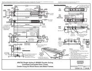
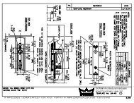
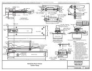
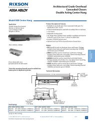
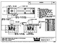
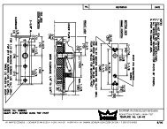
®RIXSONASSA ABLOYTemplate3/41/8Jamb2-5/8 R.Max1-7/161-1/322-5/82-3/47/8 Dia.JambC L Spindle<strong>Installation</strong> Instructions30<strong>40</strong> (05-09)9/169/32Door1/16Finish Plate1/41-1/4 Dia.3<strong>40</strong> TOP PIVOTPIVOT SHOWN ENGAGEDArmCheckingAdjustmentsFloor Plate1/4-20 x 5/8" FHMS or#14 x 1/2" FHWS5/8B15/3221/3230-<strong>40</strong> Floor CloserCenter HungDouble ActingNon-Handed6-3/41-15/32 9/32JAMB PORTION 9/321-5/1612-24 x 5/8" FHMS or 9/32#12 x 1-1/4" FHWS(2 Places) 1/4-20 x 5/8" FHMS or1-1/8#14 x 1-1/2" FHWSDOOR PORTION(2 Places)4-13/165-9/321-9/16" Min. ClearanceRequired for Arm,Arm Plate and ShimsFloorPlateDoorMortised1-9/16Deep forArm7/81-1/45/8Provide3/8" Dia.Hole1-9/163/16Floor Plate1/4 Threshold1/2 Threshold1/8 2-5/8B"B"1-1/1615/1611/16FArm Plate HD7-7/161-9/16 Dia.SpindleShoulderCollarCCement Case7/16With ThresholdUse Top (2) HolesWith Floor PlateUse Bottom(2) HolesECement Case3/16AWITH FLOOR PLATESet Cement Case 1/8" Below Surface of Finished FloorProvide 5/8" dia. hole for alignment screw.Door Mortised "A"Deep for Arm "A"Door Mortised1-9/16 Deep1/4 Threshold 1-1/8for Arm1/2 Threshold 7/83/16ThresholdCloserNumber30A5-3/8DimensionsB C5-1/2 14-9/16D15-1/8E3-5/8F2-5/16WITH THRESHOLDSet Cement Case Flush with Finished Floor<strong>40</strong>6-1/166-1/817Conversion from inches to metric: inch x 25.4.Suitable reinforcing by others.<strong>Rixson</strong> designed threshold available on request.Auxiliary stop required.<strong>Rixson</strong> Specialty Door Controls17-1/44-1/162-9/16www.rixson.com1/4-20 x 1" FHMSor #14 x 2" FWHS(4 Places)1-1/41-19/322-3/32C L Spindle 3/161-25/32 1-7/32 11/325/83-13/16ARM PLATE H29/321-13/32866-474-9766 Technical Department
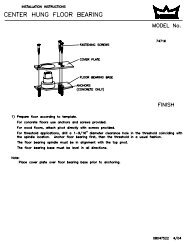
PAGE 2How To DetermineHand of DoorLHRHTop Pivot Jamb PortionTop Pivot Door PortionAdjusting ScrewIMPORTANT:Use plumb line to makesure that center line oftop pivot pin lines upwith center line of closerspindle.Arm Plate “H”Alignment ScrewsFace a door swinging open away from you. If it opens to theright, it is right hand. If it opens to the left, it is left hand.NOTE: This product allows door to swing in both directions.<strong>Installation</strong> Instructions1. Locating CloserDoorJambSpindle PositionCenterline of Doorand SpindleA. Measure 2-3/4” out from door jamb on centerline of door.This is the location of the spindle center.2-3/4” From Face ofJamb to C of SpindleL2. Install Cement Case in FloorLEVEL IN BOTHDIRECTIONSA. For floor plate application: Cement case is set 1/8”(3.2mm) below floor level.B. For threshold application: Cement case is set flush withfloor.C. Set cement case in floor and block in position.D. Case should be parallel with center line of door.E. CEMENT CASE SHOULD BE LEVEL. Place levels perIllustration.F. Grout in cement case with closer. Cement should not getbetween closer and case.<strong>Rixson</strong> Specialty Door Controls www.rixson.com 866-474-9766 Technical Department
3. Install Pivot and Closer ArmPAGE 3DOORA. Install top pivot in door per template.B. Install top pivot in jamb per template.SpindleShims (forthreshold useonly)Arm Plate “H”Closer inFloorC. Centerline of pivot pin should line up with centerlineof spindle. Use plumb line to assure accuracy.D. Mortise door for arm, arm plate “H”.E. Drill two 5/8” dia. holes for arm alignment screws. Drill3/8” hole at heel edge of door for adjusting screw.F. Install arm, arm plate “H”, and shims if required. (If1/2” threshold is used install 4 shims above arm plate“H”–refer to template. If 1/4” threshold is used install(2) 1/16” shims above plate “H”). Attach armalignment screws and washers to hold arm in place.4. Hang DoorTop PivotPinCenterlineof Door30°Pin RetractingScrewCAUTION: Closer is shipped with "valve" screws down.DO NOT FORCE VALVE DOWN.A. Retract top pivot pin by turning retracting pin screwcounter-clockwise (see illustration).B. With arm on spindle, turn spindle until arm is in 30°open position (see illustration).C. Set door on spindle arm. DO NOT ATTEMPT TOCLOSE DOOR.D. Align two portions of top pivot and turn pin retractingscrew clockwise to engage top pivot pin.E. Open door to 60° or more and turn valve screwscounterclockwise. Door will then close.F. If necessary, turn adjusting screw at bottom of heeledge of door to equalize side jamb clearances.Adjusting ScrewG. Adjust arm alignment screws equally from each sideto center door in doorway.Alignment Screws<strong>Rixson</strong> Specialty Door Controls www.rixson.com 866-474-9766 Technical Department
Closer AdjustmentPAGE 4Closing speeds can be adjusted to suit local conditions andrequirements. Label on closer face designates the purposeof each adjustment screw. Adjustments are for speedcontrol.Closer TypeThis closer is one of three types as follows:1. Non hold-open factory set. No hold-open adjustments.2. Automatic hold-open factory set. No hold-open adjustment.Spring Power AdjustmentsThis closer can be adjusted for increased or decreased spring power.These adjustments if required should be done by an authorized repair agency.Repairs, parts replacement or internal adjustments must be done by a <strong>Rixson</strong> authorized repair agency. Consultwww.rixsondoorcontrols.com for an authorized repair agency in your area.<strong>Rixson</strong>® is a registered trademark of Yale Security Inc., an ASSA ABLOY Group company. Copyright© 2002, 2009, Yale Security Inc., an ASSA ABLOY Group company.All rights reserved. Reproduction in whole or in part without the express written permission of Yale Security Inc. is prohibited.RIXSON®ASSA ABLOY<strong>Rixson</strong> Specialty Door Controls www.rixson.com 866-474-9766 Technical Department