F Series Features.pdf - Humphrey Products Company
F Series Features.pdf - Humphrey Products Company
F Series Features.pdf - Humphrey Products Company

Create successful ePaper yourself
Turn your PDF publications into a flip-book with our unique Google optimized e-Paper software.
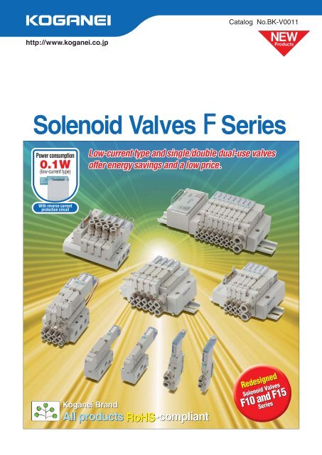
Catalog No.BK-V0011Solenoid Valves<strong>Series</strong>Power consumption0.1W(low-current type)Low-current type and single/double dual-use valvesoffer energy savings and a low price.With reverse currentprotection circuitKoganei BrandAll products RoHS-compliantRedesignedSolenoid ValvesF10 and F15<strong>Series</strong>
SOLENOID VALVES F SERIESSERIESContents<strong>Features</strong> 2Product Range 5Energy-Saving Proposal Using the Solenoid Valve F10, F15 <strong>Series</strong> 8Notification of Changes to the Solenoid Valves F10 and F15 <strong>Series</strong> Specifications 9Safety Precautions 13Operating Principles and Symbols 16Handling Instructions and Precautions 18Manifold Unit Adding Procedure 28Product Configurations for the F <strong>Series</strong> Serial Transmission Compatible Manifolds 37Specifications of Serial Transmission Compatible Manifolds 38F101544Single Valve Unit F18 72Monoblock Manifold A Type (Base Piping Type) F101546Monoblock Manifold F Type (Direct Piping Type)F18 74F101548F1876Monoblock Manifold A Type, Wire-saving Type (Base Piping Type) 50Monoblock Manifold F Type, Wire-saving Type (Direct Piping Type) 52PC Board Manifold A Type (Base Piping Type) 54PC Board Manifold F Type (Direct Piping Type) 58Split Manifold Non-plug-in Type F1015 60F1878Split Manifold Plug-in TypeF101564F1882Serial Transmission Compatible Manifold F1015 68F1886SOLENOID VALVES SERIES 103Specifications 104SOLENOID VALVES SERIES 109Specifications 110F15 SERIES F10 SERIES ORDER CODESSOLENOID VALVES SERIES 117Specifications 118F18 SERIES
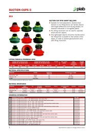
Solenoid Valves<strong>Series</strong>Environmentally friendly RoHS Compliant product !The F <strong>Series</strong> is the Result of aFocus on Usability.1Single or double dual-use valveWith the F series 2-position valves, you can use a manual override to select either the single solenoid valveor the double solenoid valve function.Note: A dedicated single solenoid valve is also available.Single solenoid positionDouble solenoid position14SA14SA4A2B5R11P3R24A2B5R11P3R212SB232-position valve(Excluding T0 type)Employs dual-use different size fittingsKoganei’s unique dual-use different sized fittings can be connected to two different types of tubes withdiffering outer diameters.No need to waste time selecting fi ttings based on the tube size.Dual-use differentsize fi ttingMountable tube sizes:F10 series: 4 and 6F15 series: 6 and 8F18 series: 8 and 10Note: A single sized fi tting canalso be selected.Connecting a6 tubeAllows the fitting block to be changed for either base piping or direct pipingSince the direction of the fitting blocks can be changed afterpurchase, the user is free to change the piping direction.(Excluding monoblock manifold F type, and PC board manifold F type)Base pipingDirect pipingConnecting a4 tubeThe same fi tting as in the left photographChanging thepositionFitting blockPlateCautionBefore use, be sure to read the “Safety Precautions” on p.13.
Redesigned Solenoid Valves F10 and F15 <strong>Series</strong>!Six characteristics make it even easier to use1More compact, lower power consumption The newly developed solenoid valve F10 and F15 series use less power.Total length reduced by 6 mm [0.236 in.].0.9WConventional standard type Note0.1WNew low-current type NoteLight blue0.4WNew standard type NoteBlueNote: With reverse current protection circuit2Tandem 3-port valve has newly been addedTwo 3-port valve functions in one valve body.Using F series valves as an air-operated valve orsingle-acting cylinder control saves space. Allows combined mounting with 5-port valve.Combined mounting with5-port valveModel4(A) side2(B) sideSymbolF10 TAF15 TAF10 TBF15 TBF10 TCF15 TCNormallyclosed(NC)Normallyopen(NO)Normallyclosed(NC)Normallyclosed(NC)Normallyopen(NO)Normallyopen(NO) Double acting type cylinders(Mini Guide Sliders)Air-operated valve, etc.(Pure Process <strong>Series</strong>)3Wire-saving type has been added to monoblock manifoldWire-saving type added to monoblock manifoldA and F types.Wiring specifi cations for fl at cable connector andD-sub connector are available.ConnectorAluminum manifold*Photo shows a F10 series monoblockmanifold F type wire-saving type.
4Stop valve (optional) has been added (Only for Monoblock Manifold)Enables replace valves without stoppingoperation of various devices andinstrumentation lines.Stop valve enables the opening andclosing of each unit’s fl ow path withoutshutting off the main air supply.5Back pressure prevention valve (optional) has been addedPrevents back pressure problems caused when operating single acting cylinders, etc.Back pressureprevention valveBack pressure prevention valveTwo back pressure prevention valves aremounted on the manifold side.This prevents cylinder malfunctions causedby the exhaust air from other valves.6Slim and compact■ Monoblock manifold F typeHeight hasbeen reduced.■ Serial transmission typeTransmission portion and manifold combined in a singlepiececonstruction.Compatible devices with serial transmission integrated manifoldFor OMRON CompoBus/S (16 outputs)For CC-Link (16 outputs)For CC-Link (32 outputs)For DeviceNet (16 outputs)For DeviceNet (32 outputs)For CompoNet (16 outputs)*Photo shows F10 series.*Photo shows F10 series.
Product RangeValve width: 10 mm [0.394 in.]Sonic conductance C: 0.97 dm 3 /(sbar)Cv: 0.27Applicable cylinder bore sizes: 20 [0.787 in.] 50 [1.969 in.]Single Valve UnitValves can be used as singleunits by attaching inlet portblocks. Mounting brackets arealso available.Valve width: 15 mm [0.591 in.]Sonic conductance C: 2.05 dm 3 /(sbar)Cv: 0.57Applicable cylinder bore sizes: 40 [1.575 in.] 80 [3.150 in.]Valve width: 18 mm [0.709 in.]Sonic conductance C: 3.6 dm 3 /(sbar)Cv: 1Applicable cylinder bore sizes:50 [1.969 in.] 100 [3.937 in.]Outlet port specificationsWith sub-baseFor single valve unit or manifold useFemale thread With female thread block With dual-use different size fitting block With single size fitting block<strong>Series</strong>Rc1/8 Rc1/4 M5 Rc1/8 Rc1/44 & 6 6 & 8 & 10 4 6 8 10NPT1/8 NPT1/4 10-32 UNF NPT1/8 NPT1/4F10 F15 F18 With fitting block With female thread block With A type sub-base With mounting bracketF10,F15Order codes p.44,45F18Order codes p.72,73Monoblock Manifold A Type (Base Piping Type)This base piping type manifoldoffers easy maintenanceand cost performance.Replacing the outlet blockenables its use as a directpiping type manifold.Using a pre-wired commonterminal plug connectorgreatly reduces wiring work.With fitting blockWith female thread blockPre-wired common terminalplug connectorF10,F15Order codes p.46,47F18Order codes p.74,75Monoblock Manifold F Type (Direct Piping Type)The direct piping type manifoldoffers excellent cost performance.Using a pre-wired commonterminal plug connectorgreatly reduces wiring work.With fitting blockWith female thread block Pre-wired common terminalplug connectorF10,F15Order codes p.48,49F18Order codes p.76,77
NEWMonoblock Manifold A Type, Wire-Saving Type (Base Piping Type)Wire-saving type of monoblock manifold A type.Wiring specifications include the flat cable connectormounting type and the D-sub connector mountingtype.With fitting blockWith female thread blockOrder codes p.50,51Note: Not available in the F18 series.NEWMonoblock Manifold F Type, Wire-Saving Type (Direct Piping Type)Wire-saving type of monoblock manifold F type.Wiring specifications include the flat cable connectormounting type and the D-sub connector mountingtype.With fitting blockWith female thread blockOrder codes p.52,53Note: Not available in the F18 series.PC Board ManifoldA MIL type 20-pin flat cable connector is installed onthe monoblock manifold to achieve both wiring savingsand cost performance. Combined use of theKoganei PC wiring system and wiring specification-F201 allows for more effective wiring savings.A type (Base piping type)F type (Direct piping type)Order codes p.5459Note: Not available in the F18 series.Split Manifold Non-Plug-in TypeEnables easy addition or removal of manifold blocks. This system offers more flexibility in conforming to changes in specifications.Manifold portwith fitting blockValve portwith fitting blockManifold portwith female thread blockValve portwith female thread blockF10,F15Order codes p.6063F18Order codes p.7880
Split Manifold Plug-in TypeManifold conforms to reducing wiring work. Adding on wiring allows adding manifold units.Combined use of the Koganei PC wiring system and wiring specification -F201 offers more effective wiring savings.F10,F15Order codes p.6467Manifold portwith fitting blockValve portwith fitting blockManifold portwith female thread blockValve portwith female thread blockF18Order codes p.8285Wiring SpecificationsFlat cable connectorvertical lead type NoteFlat cable connectorside lead type NoteD-sub connectorvertical lead type NoteD-sub connectorside lead type NoteTerminal blockNote: You can change the connector direction.For the flat cable connectorand D-sub connector, the nopower supply terminal type isalso available.Caution: For the F18 series, neither the connectorside-lead type nor the no power supplyterminal type is available.Photograph shows flatcable connector.Remark: You can also select the wiring position (wiring block) for right-side mounting.Serial Transmission Compatible ManifoldNEWFor CC-LinkFor UNILINEFor SUNX S-LINKFor OMRON B7A Link TerminalFor OMRON CompoBus/SFor CompoNetFor DeviceNet NoteNote: Not available in the F18 series.F10,F15Order codes p.6871F18Order codes p.8688Integrated type (F10, F15 series)Stand-alone typeFor details, see p. 37-40.Remark: You can also select the wiring position (transmission block) for right-side mounting.
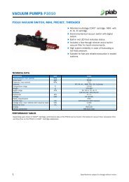
Energy-Saving Proposal Using the Solenoid Valves F10 and F15 <strong>Series</strong>Comparison of power consumption (Reference)With the cylinder conditions operating 5 seconds in the extended side and 5 seconds in the retraced side, and anoperating time of 12 hours per day, fi ve days per week, and 50 weeks per year, the power consumption for oneyear is calculated. (Annual power consumption: Power consumption per hour12 hours5 days50 weeks)Case 1: when single solenoid is used (0.4W: Standard type)Power consumption 0.4WSolenoid ON Solenoid OFF5 seconds 5 secondsCase 2: when single solenoid is used (0.1W: Low current type)Power consumption 0.4W(Startup time 70 ms)Power consumption 0.1WSolenoid ON Solenoid OFF5 seconds 5 secondsCase 3: when double solenoid is used (0.4W: Standard type)Power consumption 0.4WEnergizing timeEnergizing timeSolenoid SA ON0.05 seconds5 secondsSolenoid SB ON0.05 seconds5 secondsResults for calculation of power consumption under the above conditions, and power consumption graphSolenoidSingle solenoid (standard type)Single solenoid (low-current type)Double solenoid (standard type)Power consumption(W)0.4Starting: 0.4/holding: 0.10.4Energizing time (s)SAON SBON5 −5 −0.05 0.05Number of operationsper hour (cycles)360360360Electric energyper hour (Wh)0.2000.0520.004Remark: Comparison using new type solenoid 24VDC specifi cation. Electricity charges are assumed to be 22 yen/kWh.Annual electric energy (kWh) andannual electric energy cost0.613.2 yen0.1563.43 yen0.0120.264 yenPower consumption (kWh)0.6[13.2 yen]Power consumption(CO 2 emissions) is140.156[3.43 yen]1500.012[0.264 yen]The double solenoid valve (pulse control) shows alower electric energy result. Note that with higheroperation frequency, this difference will narrowsomewhat. With use of 0.1W low-current type,the power consumption is reduced to1/4.Furthermore, If pulse control is performed using adouble solenoid, power consumptioncan be sharply reduced. Solenoid valves F series is single/double dual use valves. Since the single solenoid and doublesolenoid are the same price Note , it alsoenables cost benefits.Note: For 2-position valve. Excluding T0 type.
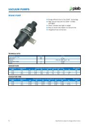
Notification of Changes to theSolenoid Valves F10 and F15<strong>Series</strong> SpecificationsThank you for using our products.Now we have undertaken to introduce some changes to thespecifi cations of the popular Solenoid Valves F10 and F15 <strong>Series</strong>(no specifi cation changes have been made to the Solenoid ValvesF18 <strong>Series</strong>).With these new solenoids, we have reduced both the wattage andtotal length of the valve. In addition, we have made the F type andserial transmission manifolds more compact.We hope for your understanding of these changes and for yourcontinued use in the future.■ Descriptions of changes● Single valve unit● Large reduction in power consumption and 6 mm [0.236 in.] shorter in total length while maintaining 100% mounting and wiringinterchangeability with the conventional model.L type plug connectorS type plug connectorUnit: mm [in.]6[0.236]6[0.236]5[0.197]5[0.197]LightblueBlueLightblueBlue6 [0.236]New New ConventionalLow-currenttype0.1WStandardtype0.4W*Photo shows F10 series. (F15 series is similar.)Standardtype0.9WNew New ConventionalLow-currenttype0.1WStandardtype0.4WStandardtype0.9W● High-speed circuit employed on coil circuit board to achieve faster OFF response.● Newly designed A and B independent coils allow for optional tandem 3-port valve.
Notification of Changes to the Solenoid Valves F10 and F15 <strong>Series</strong> Specifications● Monoblock manifold● More compact F type manifold that eliminates PR port (collected in 5 (R1) port).■ F10 <strong>Series</strong> (reference) mm [in.]New F type manifold24[0.945]14[0.551]93 [3.661]Conventional F type manifold24[0.945]14[0.551]99 [3.898] 8[0.315]49 [1.929]9[0.354]49 [1.929]93 [3.661]99 [3.898]■ F15 <strong>Series</strong> (reference) mm [in.]New F type manifold33 [1.299]18[0.709]113.5 [4.469]Conventional F type manifold33 [1.299]18[0.709]119.5 [4.705] 10[0.394]64 [2.520]14[0.551]61 [2.402]113.5 [4.469]119.5 [4.705](80.5 [3.169])(86.5 [3.406])(61 [2.402])20[0.787]26[1.024]24[0.945](67 [2.638])PR portNo PR port for thenew F type manifold.● Optional back pressure prevention valve for both the A type and F type manifolds now available.● Optional sandwich-type stop valve now available.30[1.181]PR portNo PR port for thenew F type manifold.
● Split type manifold/serial transmission compatible manifold● Coil portion fl attened by minimizing the valve size.● Enables selection and switching between upward-facing and side-facing for fl at cable connector and D-sub connector installation.● Optional no power supply terminal type (standard type comes with power supply terminal) now available.● More compact serial transmission device and manifold combined in single-piece construction (some models connected with fl at cable).● Optional back pressure prevention valve now available.● Changed color of a valve base assembly cover from light blue to ivory in order to enable identifi cation between the conventional type andnew type. (For differentiation between new and conventional type, see p.12.)■ F10 <strong>Series</strong> split manifold plug-in type (reference) mm [in.]New manifoldConventional manifoldConnector positionschanged to outside ofend block (excludingterminal block type).112.5 [4.429]120 [4.724]For no power supplyterminal typeDirection of power supplyterminal changed.Shape of end block changed.■ F15 <strong>Series</strong> split manifold plug-in type (reference) mm [in.]New manifoldConventional manifold147 [5.787]154 [6.063]■ F10 <strong>Series</strong> serial transmission compatible manifold (reference) mm [in.]New manifoldConventional manifoldIntegrated type(Compatible with CC-Link, DeviceNet, CompoNet, and CompoBus/S)62 [2.441] 146.5 [5.768]74.3 [2.925] 171.5 [6.752] Stand alone type (flat cable connection)(Compatible with UNILINE, SUNX S-LINK, and OMRON B7A Link Terminal)74.3 [2.925] 164 [6.457]* While dimensions show F10 <strong>Series</strong>,the F15 <strong>Series</strong> is similar.
Notification of Changes to the Solenoid Valves F10 and F15 <strong>Series</strong> Specifications■ Reference photo: Valve base assembly (Photo shows F10 <strong>Series</strong>.)New manifoldConventional manifoldColor of cover: IvoryColor of cover: Light blueOthers1. Gasket for monoblock manifold (aluminum)With addition of the back pressure prevention valve as an option, some of the gasket dimensions have changed.Consequently, please be aware that while the side of the gasket that interfaces with the valve is interchangeable for boththe conventional and new valves, the side of the gasket that interfaces with the manifold is not.New GasketConventional GasketProtrusion of 0.5 mm2. Differentiating new and conventional types of monoblock manifold A typeNew manifoldConventional manifoldIdentification mark (2)3. ConnectorsNew connector (gray)Conventional connector (black)There have been no changes in shapes.
Safety Precautions (Solenoid Valves F <strong>Series</strong>)Always read these precautions carefully before use.Before selecting and using products, please read all the Safety Precautions carefully to ensure proper product use.The Safety Precautions shown below are to help you use the product safely and correctly, and to prevent injury or damage to you, otherpeople, and assets beforehand.Follow the Safety Precautions for: ISO4414 (Pneumatic fluid power—Recommendations for the application of equipment to transmissionand control systems), JIS B 8370 (Pneumatic system regulations)The directions are ranked according to degree of potential danger or damage: DANGER!WARNING!CAUTION!and ATTENTION!DANGERWARNINGExpresses situations that can be clearly predicted as dangerous.If the noted danger is not avoided, it could result in death or serious injury.It could also result in damage or destruction of assets.Expresses situations that, while not immediately dangerous, could become dangerous.If the noted danger is not avoided, it could result in death or serious injury.It could also result in damage or destruction of assets.CAUTIONATTENTION This product was designed and manufactured as parts for use in General Industrial Machinery. In the selection and handling of equipment, the system designer or other person with fully adequate knowledge and experienceshould always read the Safety Precautions, Catalog, Owner’s Manual and other literature before commencing operation. Makingmistakes in handling is dangerous. After reading the Owner’s Manual, Catalog, etc., always place it where it can be easily available for reference to users of this product. If transferring or lending the product to another person, always attach the Owner’s Manual, Catalog, etc., to the product where it iseasily visible, to ensure that the new user can use the product safely and properly. The danger, warning, and caution items listed under these “Safety Precautions” do not cover all possible cases. Read the catalog andOwner’s manual carefully, and always keep safety first. Do not use for the purposes listed below:1. Medical equipment related to maintenance or managementof human lives or bodies.2. Mechanical devices or equipment designed for the purposeof moving or transporting people.3. Critical safety components in mechanical devices.This product has not been planned or designed for purposesthat require advanced stages of safety. It could cause injury tohuman life. Do not use in locations with or near dangerous substancessuch as flammable or ignitable substances. This product is notexplosion-proof. It could ignite or burst into flames. When attaching the product, always firmly support and securethem (including workpieces) in place. Dropping or falling of theproduct or improper operation could result in injury. Persons who use a pacemaker, etc., should keep a distanceof at least 1 meter [3.28ft.] away from the product. There is apossibility that the pacemaker will malfunction due to thestrong magnet built into the product. Never attempt to remodel the product. It could result inabnormal operation leading to injury, etc. Never attempt inappropriate disassembly, assembly or repairof the product’s basic construction, or of its performance orfunctions. This could result in injury, electric shock, fire, etc. Do not splash water on the product. Spraying it with water,washing it, or using it underwater could result in malfunctionof the product leading to injury, electric shock, fire, etc. While the product is in operation, avoid touching it with yourhands or otherwise approaching too close. In addition, do notmake any adjustments to the interior or to the attachedmechanisms (manual override, connecting and disconnectingof wiring connectors, adjustment of pressure switches, orrelease or connection of piping tubes or plugs) while inoperation. The actuator can move suddenly, possibly resultingin injury.Expresses situations that, while not immediately dangerous, could become dangerous.If the noted danger is not avoided, it could result in light or semi-serious injury.It could also result in damage or destruction of assets.While there is little chance of injury, this content refers to points that should be observed forappropriate use of the product.DANGERWARNING Do not use the product in excess of its specification range.Such use could result in product breakdowns, function stop,damage or drastically reduce the operating life. Before supplying air or electricity to the device and beforestarting operation, always conduct a safety check of the areaof machine operation. Unintentional supply of air or electricitycould possibly result in electric shock, or in injury caused bycontact with moving parts. Do not touch the terminal and the miscellaneous switches,etc., while the device is powered on. There is a possibility ofelectric shock and abnormal operation. Do not throw the product into fire. The product could explodeand/or release toxic gases. Do not sit on the product, place your foot on it, or place otherobjects on it. Accidents such as falling or tripping over theproduct could result in injury. Dropping the product could resultin injury, or also damage or break it resulting in abnormal orerratic operation, or runaway, etc. When conducting any kind of operation for the product, such asmaintenance, inspection, repair, or connection/disconnection orreplacement of piping, always turn off the air supply completelyand confirm that residual pressure inside the product or in pipingconnected to the product is zero before proceeding. In particular,be aware that residual air will still be in the air compressor,vaccum pump or air storage tank. The actuator could abruptlymove if residual air pressure remains inside the piping, causinginjury.Before commencing normal operation, always release the lockof the locking type manual override, and confirm that themanual override is in the normal position and that the mainvalve is in the proper switching position, and only thencommence the operation. Failure to do so could lead toerroneous operation. Always shut OFF the power before wiring operations. Wiringwith the power ON could result in electric shock. Always apply the stipulated amount of voltage to the solenoid.Applying the wrong voltage could result in failure to performthe intended function, and could damage or burn the productitself. Avoid scratching the cords of lead wires, etc. Letting the cordsbe subject to scratching, excessive bending, pulling, rollingup, or being placed under heavy objects or squeezed betweentwo objects, may result in current leaks or defective continuitythat lead to fire, electric shock, or abnormal operation. Do not pull out the connectors while the power is ON. Also, donot apply unnecessary stress on the connector. It could resultin erratic equipment operation that could lead to personalinjury, equipment breakdown, or electrical shock, etc. Always check the Catalog to ensure that the product wiringand piping is done correctly. Errors in wiring and piping couldlead to abnormal operation of the actuators, etc.In the first operation after the equipment has been idle for 48hours or more, or has been in storage, there is a possibilitythat contacting parts have got stuck, resulting in equipmentoperation delays or sudden movements. For these firstoperations, always run a test operation before use to checkthat operating performance is normal.
Safety Precautions (Solenoid Valves F <strong>Series</strong>)Always read these precautions carefully before use.In low frequency use (more than 30 days between uses), there is apossibility that contacting parts may have stuck toghter, resulting inequipment operation delays or sudden movements that could leadto personal injury. Run a test operation at least once every 30 daysto confirm that movement is normal.For double solenoid type (excluding the Tandem 3-port valve), donot apply current through both solenoids simultaneously. It isimpossible in such a situation to maintain the correct valve position,and the equipment may operate in an unintended direction, leadingto the possibility of equipment breakdown or personal injury.Do not use the solenoid valves or the wiring that controls them, nearpower lines where large electrical currents are flowing, or inlocations subject to high magnetic fields or power surges. Suchapplication could lead to unintended operation.The solenoid valve can generate surge voltage and electromagneticwaves when the switch is turned OFF, affecting the operations ofsurrounding equipment. Use solenoids with surge suppression, ortake countermeasures in the electrical circuits for surges orelectromagnetic waves.Do not use the product where ozone may be generated, such asnear ocean beaches or other places subject to direct sunlight ormercury lamps. Ozone can cause rubber parts to deteriorate, whichcan lead to degraded performance and functions, or to equipmentstoppages. (Excludes items where measures against ozone havebeen taken.)Do not use any media other than shown on the specifications. Use ofnon-specified media could lead to functional shutdown after a shortperiod, to sudden performance drops, or to shorter operating life.If mounting the solenoid valve inside a control panel, or if energizingit for long periods, provide heat radiation measures to ensure thattemperatures surrounding the solenoid valve always remain withinthe specified temperature range. In addition, if energizingcontinuously over long periods, rising temperatures due togeneration of heat in the coil can lead to a decline in solenoid valveperformance and operating life, and have adverse effects on nearbyequipment. As a result, when the solenoid valve is continuouslyenergized over long periods of time, or when the solenoid valve isenergized for longer periods than it is non-energized on any day, agood suggestion is to keep the solenoid valve in a normally open(NO) specification as one possible method of reducing the amountof time the valve is energized. For details, consult us.After wiring operations, always check to ensure that no wiringconnection errors exist before turning ON the power.Do not collect the exhaust lines for air cylinders, etc. with pilotexhaust lines for solenoid valves into the same piping, etc.Interference in the exhaust could result in erratic operation.When using the valve in a manifold, be aware when driving an aircylinder or performing air blowing operations that back pressurecould cause erratic operations of the cylinder or erroneous airdelivery from the air blow port. Caution is particularly needed whenusing valves with 3-position exhaust center specification, whenoperating single acting cylinders, or when operating a cylinder andblowing air using the same manifold. If there are concerns in thisarea, take such countermeasures as using individual exhaustspacers or back pressure prevention valves.CAUTION When mounting the product, leave room for adequate workingspace around it. Failure to ensure adequate working space willmake it more difficult to conduct daily inspections or maintenance,which could eventually lead to system shutdown or damage to theproduct. For mounting or transport of heavy products, use a lift, supportingtool, or several people, to provide firm support, and proceed withdue caution to ensure personal safety. Do not bring magnetic media, within 1 meter [3.28 ft.] of the product.There is the possibility that the data on the magnetic media will bedestroyed due to the magnetism of the magnet. If leakage current is flowing in the control circuit, there is a possibilityof the product performing an unintended operation. Take measuresagainst current leaking in the control circuit, to ensure that theleakage current value does not exceed the allowed range in theproduct specifications. Do not block the product’s breathing holes. Pressure changes occurdue to changes in volume during operation. Blocking the breathingholes destroys the pressure balance, and could cause failure of theintentional operation, equipment damage, or personal injury. Do not use the solenoid valve in locations subject to large electricalcurrents or magnetic fields. It could result in erratic operation. Oily materials from the compressor (excluding the oil-free compressor)can cause drastic deterioration in product performance, and even afunctional shutdown. Always install a mist filter before pneumaticequipment to remove the oily component. The properties of the lubrication oil can change when used in dry airwhere dew point temperatures is lower than –20°C [–4°F]. It couldresult in degraded performance or in functional shutdown. Do not use the product in locations that are subjected to directsunlight (ultraviolet ray), to dust, salt, or iron powder, high temperature,high humidity or in media or ambient atmospheres that includeorganic solvents, phosphate ester type hydraulic oil, sulfur dioxide,chlorine gas, acids, etc. It could lead to an early shutdown of somefunctions or a sudden degradation of performance, and result inreduced operating life. For materials used, see Major Parts andMaterials. Always carefully wash your hands after touching oil or grease usedin the valves. If you smoke a cigarette while there is oil or greaseremains on your hands, oil or grease transferred to the cigarettecould catch fire and emit toxic gases.ATTENTION When considering the possibility of using this product in situations orenvironments not specifically noted in the Catalog or Owner’sManual, or in applications where safety is an important requirement,such as in an airplane facility, combustion equipment, leisureequipment, safety equipment and other places where human life orassets may be greatly affected, take adequate safety precautionssuch as application with enough margins for ratings andperformance or fail-safe measures. Be sure to consult us with suchapplications. Always check the Catalog and other reference materials for productwiring and plumbing setup. Install a muffler, etc. on the exhaust port. It is effective in reducingexhaust noise. When handling the product, wear protective gloves, safety glasses,safety shoes, etc. to keep safety. When the product can no longer be used or is no longer needed,dispose of it appropriately as industrial waste in accordance with theWaste Disposal and Public Cleaning Law, and other ordinances andregulations imposed by local government authorities. As incinerationdisposal of oil or grease used in the valves will generate corrosive, toxichydrofluoric acid (HF), dispose of these compounds in an acid-resistantincinerator with toxic removal facilities. For large volumes, use aregistered industrial waste disposer. Pneumatic equipment can exhibit degraded performance and functionover its operating life. Always conduct daily inspections of thepneumatic equipment, and confirm that all requisite system functionsare satisfied, to prevent accidents from happening. Air leaks from the valve are not zero. For application of requiringholding pressure (including vacuum) inside the pressure vessel,consider adequate margin of capacity and holding time in design ofthe system. For inquiries about the product, consult your nearest Koganei salesoffice, or Koganei overseas department. The address andtelephone number is shown on the back cover of this catalog.OTHERS Always observe the following items.1. When using this product in pneumatic systems, always usegenuine KOGANEI parts or compatible parts (recommendedparts).When conducting maintenance and repairs, always use genuineKOGANEI parts or compatible parts (recommended parts).Always observe the required methods and procedure.2. Do not attempt inappropriate disassembly or assembly of theproduct relating to basic configurations, or its performance orfunctions.Koganei cannot be responsible if these items are not properlyobserved.
Handling Instructions and PrecautionsGeneral PrecautionsMounting1. While any mounting direction is allowed, be sure to avoidstrong shocks or vibrations applied directly to the body.2. Avoid using in the locations and environment listed below, as itcould result in malfunction of the valve. If use in suchconditions is unavoidable, always provide a cover or otheradequate protective measures.● Location directly exposed to water drops or oil drops● Environment where a valve body is subject to dewcondensation● Location directly exposed to machining chips, dust, etc3. In piping connection with valves, flush the tube completely (byblowing compressed air) before piping.Intrusion of machining chips or sealing tape, rust, etc.,generated during plumbing could result in air leaks and otherdefective operations.4. Never use the valve with the 4(A) and 2(B) ports vented to theatmosphere.5. When mounting a valve inside a control panel, or whenenergizing time is long, make adequate consideration forventilation and other heat dissipation measures.6. When adding or subtracting units in the manifold, or replacinga fitting block, be sure to tighten to within the specifiedtightening torque range.Media1. Use air for the media. For the use of any other media, consult us.2. Air used for the cylinder should be clean air that contains nodeteriorated compressor oil, etc. Install an air filter (filtration of40 µm or less) near the valve to remove collected liquid ordust. In addition, drain the air filter periodically.3. When supply pressure is low, use piping for the 1(P) port withsufficient tube size.LubricationCan be used without lubrication due to the factory lubricant(grease). When the pneumatic products require lubrication, useTurbine Oil Class 1 (ISO VG32) or the equivalent. In addition,cutting off oil feed while an operation is in progress could lead tomalfunction due to the dissipation of the factory lubricant(grease). As a result, always keep the oil feed runningcontinuously. However, use caution since excessive oil feed canalso be a cause of malfunction. Avoid using spindle oil ormachine oil.AtmosphereThe product cannot be used when the media or ambientatmosphere contains any of the substances listed below.Organic solvents, phosphate ester type hydraulic oil, sulphurdioxide, chlorine gas, or acids, etc.WiringAfter wiring, check that there is no error in the wiring connections.PipingSince the 1(P), 3(R2), and 5(R1) ports are on both ends of themanifold, piping direction can be selected depending on theapplication (in monoblock manifolds).At shipping, plugs are temporarily screwed in ports at one end,but are not firmly tightened. Regardless of which end piping isconnected, always remove the plugs, use sealing tape or applyother sealing agent, and securely tighten the plugs into theunused ports.1. Sealing tape wrapping methodq Before piping, perform air blowing (flushing) or cleaning toeliminate any machining chips, cutting oil, or dust, etc.,remaining inside the pipes.w When screwing in piping or fittings, caution should be taken toavoid letting machining chips or sealing materials fromentering into the valves. When using sealing tape, wrap it sothat 1.5 2 screw threads remain.Wrapping directionLeave about 2 screw theadsSealing tapePrevention of erratic operation in the manifold typeWhen using a manifold-type valve to operate an air cylinder, orto perform air blowing or similar operations, erratic operation dueto exhaust interference or malfunction due to insufficient flowrate could occur. When using the manifold type valves, be sureto take the following measures beforehand.1. Erratic operation due to large exhaust flow rateCause: When a large-bore cylinder is operating, or multiplecylinders are operating at the same time, the exhaust air inthe collective exhaust can flow backward through theexhaust ports of other solenoid valves. This could lead to anobstruction of the operations of other cylinders and maycause erratic operation in single acting cylinders or an AirHand module due to inflow of air into them. The erraticoperation is caused by insufficient manifold exhaust (largeexhaust resistance).Countermeasure: To reduce the exhaust resistance, for thebase monoblock manifold, vent the exhaust ports at bothends. For the split manifold, attach piping blocks to bothends to exhaust from both sides. If still affected even afterexhausting from both ends, consider splitting the manifold,or if using a split manifold, either install a port isolator toseparate the exhaust, or use a back pressure preventionvalve.2. Malfunctions due to insufficient pressure or flow rateCause: When operating a large-bore cylinder, operatingmultiple cylinders at the same time, or using circuits toperform air blowing, etc., sudden consumption of air withthe manifold type can result in insufficient flow rate tonearby cylinders, causing a reduction in speed or ashortage of thrust. In addition, in the pilot-type valve, thissudden consumption can lead to a pressure shortage forthe pilot signals, and it causes erratic operations in the mainstem.Countermeasure: Because it causes insufficient air delivery tothe manifold, supply air from both ends of the manifold, orfrom the piping block 1(P) port mounted on both sides. Forair blowing, consider either dividing the air lines forindependent use, or use of an external pilot valve.
Operating Principles and Symbols5-port, 2-positionWhen set as a single solenoidor T0 type14SAWhen set as adouble solenoid14SARemark: 1. When using a 5-port valve as a 3-portvalve, see p.22.2. For the F18 series, some of the shapesdiffer from the diagram. In addition, theF18 series is a molded solenoid.FT1 -A1(De-energized)Solenoid A 14SASolenoid cover4A2BXP2 Note15R11P3R24A2BXP2 Note1Solenoid B12SB Note 3ColumnMoldless solenoid12SB5R11P3R2PlungerManual overridePilot valve bodyPlunger springFlapperPistonInternal pilot Note 2Manual override Note 3 Diagram shows the F15single solenoid case.End cover5-port, 3-positionLip sealXP2External pilot Note 15R14A1P2B3R2StemValve bodyNotes: 1. For external pilot type2. Not available with external pilot type3. Not available with T0 type(Both 14 (SA) and 12 (SB) are de-energized)Major Parts and MaterialsPartsMaterialsBodyStemLip sealFlapperValveSub-basePlungerColumnEnd coverAluminum die-castingAluminum alloySynthetic rubberAluminum alloy (anodized)Magnetic stainlesssteelPlasticMonoblock Aluminum alloy (anodized)ManifoldSplit type PlasticBlock-off plate Mild steel (nickel plated)Seal Synthetic rubberBodyClosed center 14SAExhaust center 14SAFT3-A1 FT4-A1 FT5-A114SA4A2B5R11P3R24A2B5R11P3R24A2B5R11P3R2XP2 Note112SBPressureXP2centerXP2 Note1 Note112SB12SBNote2PRXP2 Note15R1Note2PRXP2 Note15R1Note2PRXP2 Note15R14A4A4A1P1P1P2B2B2B3R23R23R2Notes: 1. For externalpilot type2. Not availablewith externalpilot type
Tandem 3-port, 4-position (F10, F15 series only)(Both 14 (SA) and 12 (SB) are de-energized)Normally closed (NC) & normally closed (NC) Normally open (NO) & normally open (NO) Normally closed (NC) & normally open (NO)14SAFTA-A1 FTB-A1 FTC-A14A5R11P2B3R212SB5R15R15R14A4A4A1P1P1P2B2B2B3R23R23R2
Handling Instructions and PrecautionsSolenoidSingle and double solenoid switching procedureBy switching the manual override, model FT12-position valvecan beused as either a single solenoid valve or a double solenoid valve (switchingnot possible with a 3-position valve and a tandem 3-port valve). Notethat the FT1 is set to the single solenoid specification at shipping.Switching from a single solenoid valve to a double solenoid valve1.As shown in Fig.1, insert theflatblade edge of a smallscrewdriver into the gapbetween the valve and thecover, and then peel it off andremove the cover.Caution: As shown in Fig.1, makesure to insert a smallscrewdriver from theside of the valve cover.The cover claw may bedamaged when thecover is removed fromthe direction of the valvestem. Never remove thecover for any reasonother than valve functionswitching.2.As shown in Fig.2, use asmall screwdriver, etc. to turnthe manual override on the Bside by 90 degrees in thecounterclockwise direction,so that the manual overridebutton’s slit is horizontal, asshown on the right side of thefigure. Then the unit can beused as a double solenoidvalve. When using it as a doublesolenoid valve, the buttonis used as the manual overridebutton for the B side.Caution: When using it as a doublesolenoid valve, do notattach the cover that wasremoved in Fig. 1.Switching from a double solenoid valve to a single solenoid valveAs shown in Fig.3, use aPush lightly, then turn thesmall screwdriver, etc. to pushmanual overrride buttonlightly against the manual overridebutton, and then turn it byclockwise to set as the singlesolenoid.90 degrees in the clockwiseManual override buttondirection, so that the manualoverride button’s slit is in thevertical direction, and thenattach the cover.Caution: The cover has directionality(F15 and F18series only). Whenattaching, always alignthe detent on the backof the cover with themanual override button’sslit, as shown in Fig.4.CoverClaw Illustration shows the F10 series.Figure 1Turn the manual overridebutton in the counterclockwisedirection to set as thedouble solenoid.B side manual overridebuttonSingle solenoid state Double solenoid stateThe manualoverridebutton isprotruding.Figure 2Double solenoid state Single solenoid stateThe manualoverridebutton isprotruding.Figure 3Cover(Back face)Wiring instructions (When used as a single unit, non-plug-in type manifold)1. Attaching and removing plug connectorUse fingers to insert the connector into the pin, push it in until thelever claw latches onto the protruded section of the connectorhousing, and complete the connection.To remove the connector, squeeze the lever along with the connector,lift the lever claw up from the protruded section of the housing,and pull it out.HousingProtruded sectionPinHookContactLead wirePlug connectorPlug connectorHousingContactLead wire (white)Protruded sectionPinLeverCautions: 1. When removing the connector, confirm that the lever claw is positivelydisengaged from the protruded section before pulling out.The housing may be damaged if it is pulled out while engagedwith the protruded section.2. The plug connector lead wires for model F T1 (2-position valve)are set to the single solenoid specification at shipping (for plugconnector types).2. When switching from a single solenoid to a double solenoid specificationfor use, disconnect the plug connector from the valve,check the hook directions on the lead wire (white) with the contacts,and then insert the lead wire into the plug connector’s Bside hole (see the illustration above). Use the same procedureto switch the manifold type single solenoid to a double solenoidspecification.3. When using the plug-in type manifold, caution should beexercised that even if the valve has been switched to a doublesolenoid, no power will be supplied to the B side solenoid unlessthe valve base wiring is set to the double wiring.2. Attaching and removing plug connector and contact AttachingInsert the contact with a lead wire into a plug connector hole untilthe contact hook latches on the connector and is secured to the plugconnector. Confirm that the lead wire cannot be easily pulled out(see the diagram below). RemovingTo remove it, insert a tool with a fine tip (such as a small screwdriver)into the rectangular hole on the side of the plug connector to pushdown on the hook, and then pull out the lead wire. When re-using thecontacts, restore the hook back so that they spread outward.Indication of polarity (DC)3. Common terminal and short barA short bar is attached to the plug connector to ensure that the solenoidA and B wiring are positive common. Do not remove theshort bar.Note about the wiring forthe above switchingSee the “Wiring instructions” tothe right.End coverFigure 4DetentManual overrrideShort barContact (without lead wire)
4. Crimping of lead wire and contactTo crimp lead wires into contacts, strip off 4 mm [0.16 in.] of the insulationfrom the end of the lead wire, insert it into the contact, and crimp it. Be sureto avoid catching the insulation on the exposed wire crimping section.Insulation crimp tabExposed wire crimping sectionContactHookInsulationMaximum outer diameter:1.5 [0.059 in.]Exposed wire 4 mm [0.16 in.]Lead wireApplicable toAWG2430Cautions: 1. Do not pull hard on the lead wire.2. For crimping of lead wire and contact, always use a dedicatedtool.Contact: Model 706312-2MK Manufactured by Sumiko Tech, Inc.Crimping tool: Model F1 (for 706312-2MK) Manufactured by Sumiko Tech,Inc.5. F10, F15 Common connector assemblyUsing a common connector assembly for solenoid valves for a manifoldprovides common wiring for all the solenoid valves and greatlyreduces wiring work.The common connector assembly types are determined by looking atthem from the lead wire side; the right end one is A type, the left endone is C type, and all the others are B type (see Fig. 5). (see figurebelow).For positive commonSingle solenoid valveDouble solenoid valveCommon wire(Red)C typeSingle solenoid valveDouble solenoid valveCommon wire(Black)C type B typeA type Common wire(Red)Common wireFigure 5For negative common (F10, F15 series only) Note(Red)In the new F10, F15 series, you can order the separately soldcommon connector assembly for use with negative commonspecification.Note: Cannot be used with the conventional F10, F15 series.B typeA typeCommon wire(Black)Common wire(Black)Figure 6If ordering the common connector assembly, order from the commonconnector assemblies listed below.For positive common (F10 and F15 series)A type Model: JAZ-PA B type Model: JAZ-PB C type Model: JAZ-PC JAZ0-P6. Common connector assembly for F18 (positive common specification only )For adding units after mounting the connector assembly for the manifold,order the appropriate common connector assembly shown below.A type Model: FZ-PA B type Model: FZ-PB C type Model: FZ-PC FZ0-P Blank3 For negative common (F10 and F15 series)A type Model: JAZ-MA B type Model: JAZ-MB C type Model: JAZ-MC Blank3 Blank3The common connector assembly types are determined by looking atthem from the lead wire side; the right end one is A type, the left endone is C type, and all the others are B type (see Fig. 5).7. Cabtyre cableCC1.51500 mm [59 in.]CC33000 mm [118 in.]32.2 mm [1.268 in.]4.2[0.165 in.]ConnectorCapCaution: Exercise caution that this is not dust-proof and drip-proofspecification.
Handling Instructions and PrecautionsInternal circuitFor F10, F15 <strong>Series</strong>Voltagespecification24VDC12VDCColor of lead wire: BlackAColor of leadwire: RedInside the connectorCOMInternal circuitRed14SAFor F15, 18 <strong>Series</strong> DIN connector typeVoltageInternal circuitspecification-39L24VDC12VDC22RedColor of lead wire: WhiteBGreen12SB1−31Frame24VDCInsidef the connectorColor of lead wire: BlackARedColor of leadwire: RedCOMColor of lead wire: WhiteBGreenTimercircuitTimercircuit14SA12SB120VAC240VAC-39L2 2131Frame100VACColor of lead wire: BlackAColor of leadwire: RedCOMColor of lead wire: WhiteBInside the connectorRedGreen14SA12SBCautions: 1. Do not apply megger between the pins.2. Leakage current inside the circuit could result in failure of thesolenoid valve to return, or in other erratic operation. Always useat less than the allowable leakage current shown in the solenoidspecifications on p.111, and 119. If circuit conditions etc. causethe leakage current to exceed the allowable leakage current,consult us.3. For the double solenoid specification, avoid energizingboth solenoids at the same time.For F18 <strong>Series</strong>VoltagespecificationColor of lead wire: BlackColor of leadwire: RedColor of lead wire: WhiteInternal circuitInside the connectorInside the connectorRedGreen14SA12SBPC board manifoldWhen connecting a power lineto the power supply terminalon the PC board manifold,care should be taken in regardto the following points whenconnecting.Power supply terminalColor of lead wire: BlackColor of leadwire: RedColor of lead wire: WhiteRedGreen14SA12SBCautions: 1. Do not apply megger between the pins.2. Leakage current inside the circuit could result in failure of thesolenoid valve to return, or in other erratic operation. Always useat less than the allowable leakage current shown in the solenoidspecifications on p.104, 110, and 118, If circuit conditions etc.cause the leakage current to exceed the allowable leakage current,consult us.3. For the double solenoid specification, avoid energizingboth solenoids at the same time (except for tandem 3-portvalve).4. For the housing color, standard type is blue and low-currenttype is light blue (F18 is black).5. The low-current type will not operate if the power voltage isgradually increasing. Always apply a suitable voltage.6. For the T0 type, there is one solenoid.Terminal screw tightening torque: 0.4 N m [3.5 in lbf]Stripped wire length: 7 mm [0.28 in.]Connecting wire size: 0.132.5 mm 2 [0.000200.00388 in. 2 ]AWG: No.26...14When planning to use crimp-style terminals, use bar terminals.Recommended crimp-style terminals (bar terminals):Manufactured by Nichifu, Inc.Model BT1.25-9-1 (for 0.251.65 mm 2 [0.000390.00256 in. 2 ])Wiring of the terminal blockCare should be taken with the terminal screw tighteningtorque. Overtightening beyond the tighteningtorque could result in breakage.Terminal screw tightening torque: Max. 49.0 N cm[4.3 inlbf].
Operating principles for the low-current typeThe low-current type uses a timer circuit, as shown on the previouspage, that achieves power consumption savings by switching to aholding operations mode after a certain period of time to operate atabout 1/4 of the starting power consumption. Power waveformManual override lever (locking and non-locking dual-use type)To lock the manual override lever, use fingers to push the lever all theway down and turn it clockwise 90 degrees. To release the manual override,turn the lever 90 degrees counterclockwise, which will release themanual override lock by spring action and return it to its normal position.To operate the unit in the same way as the non-locking type, leave thelever unturned.Solenoid valvePower 0.4Wconsumption 0.1WONStart-up time (70 ms)OFFReduced powerconsumptionCaution: Model F T1 (2-position valve) has a manual override lever on the Aside, and a manual override button with cover on the B side.Model F T2 has a manual override lever on the A side only, and amanual override button on the B side.The 3-position valve has manual override lever on both the A and Bsides.Manual override leverPrecautions for use of the double solenoidWhen using models FT1 or FT2 (2-position valve) as double solenoidvalves, caution should be exercised as energizing the A sidesolenoid or pushing the manual override button on the A side, whilepushing the B side manual override button or in a locked state, or energizingthe solenoid on the B side, will cause the valve to switch over theposition. (At that time, the valve will operate in the same state as thesingle solenoid valve.)PUSHTURNA side manualoverride buttonB side manualoverride button Illustration shows the F10 series.Manual overrideManual override button (locking and non-locking dual-use type)To lock the manual override, use a small screwdriver to push down themanual override button all the way down and turn it clockwise 90degrees. To release the manual override, turn the button 90 degreescounterclockwise, which will release the manual override lock by springaction and return it to its normal position. To operate the unit in thesame way as the non-locking type, leave the manual override buttonunturned.Cautions: 1. The F series valves are pilot type solenoid valves. As a result, themanual override cannot switch the main valve without air suppliedfrom the 1(P) port (X(P2) port for external pilot type).2. Always release the lock of the manual overrides before commencingnormal operation. Caution should be exercised to release thelock of the manual override on the B side that also works as theswitching button between the single solenoid and double solenoid(excluding the 3-position valve and tandem 3-port valve). Fordetails, see “Switching from a double solenoid valve to a singlesolenoid valve” on p.18.3. Do not attempt to operate the manual override button with a pin orother object having an extremely fine tip. It could damage themanual override button.4. Take care to avoid excessive turning of the manual override button,it could damage the override.5. When operating the solenoid valve’s manual override button formaintenance etc. always confirm that the solenoid valve’s overridebutton has been restored to its normal position, and that the mainvalve is in the required switching position before restarting operations.Locking protruding type -83Use a small screwdriver or the fingers to press down and rotate themanual override button by at least 45 degrees, to lock in place. Eitherrotation direction is acceptable. In the locked position, rotate further themanual override which will release the manual override lock by springaction and return it to its normal position. If the manual override is notrotated, the unit can be operated in the same way as the non-lockingtype.PUSHTURNLocking protruding typemanual override button
Port isolatorIn the split manifold, installing port isolators to the 1(P), 3(R2) and 5(R1)ports between each station isolates the air path between stationsequipped with port isolators and stations with smaller station numbers.However, a piping block must be placed on both ends.Port isolator for the 1(P) port(Model : F Z-SP)Port isolators forthe 3(R2), 5(R1) ports(Model : F Z-SR)Port isolators forthe 1(P), 3(R2), 5(R1)ports(Model : F Z-SA )Can supply two differentpressuresCan isolate exhaust air(prevents exhaust interference)Can supply two different pressures,and can isolate exhaust air(prevents exhaust interference) denotes valve size.F10, F15 series SP: Port isolator forthe 1(P) portSR: Port isolators for the 3(R2),5(R1) portsF18 series SP: Port isolator forthe 1(P) portSR: Port isolator for the 3(R2),5(R1) portsCaution: Installing port isolators requires the disassembly and re-assembly ofmanifolds. See the disassembly illustration, unit adding procedure,and cautions on p.2833.However, since the F18 series serial transmission compatible manifoldcannot be disassembled, port isolators cannot be installed on itafter purchase.
Handling Instructions and PrecautionsPrecautions for the use of individual air supply and exhaust spacersBy mounting an individual air supply or exhaust spacer on the manifold,the air supply or exhaust can be operated individually on theunit. It is also effective in preventing erratic operation due to backpressure. Caution should be exercised when spacers are used, asthe effective area is reduced by about 30%. If mounting additionalspacers to an existing unit, observe the following items: Spacer mounting procedure(F10 series)q Loosen the valve mounting screws where the individual air supply orexhaust spacer will be installed, and remove the valve.w Install the gaskets and exhaust valve provided with the individual air supplyor exhaust spacer, and use the mounting screws provided to securethe valve on the manifold (see Fig. 7).Remark: When attaching fittings to the F10 spacer, use the recommendedfittings shown below:Remark: TSH4-M5M, TSH4-M5, TSH6-M5M, TS4-M50, TS4-M5M Spacer mounting procedure (F 15 and F18 series)q Loosen the valve mounting screws where the individual air supply orexhaust spacer will be installed, and remove the valve.w Open the cover of the manifold, and pull out the plug-in connector in thenear side direction (for the plug-in type) (see Fig. 8).e Insert the plug-in connector firmly into the connector attaching sectionof the individual air supply or exhaust spacer, and then close the cover,while watching to ensure that the lead wires are not caught by the cover(for the plug-in type) (see Fig. 9).r Attach the gasket and exhaust valve provided with the individual airsupply or exhaust spacer, and use the mounting screws provided tomount the valve on the manifold.Exhaust valveMounting screwGasketIndividual air supply orexhaust spacerFigure 7F10 series(Illustration shows the split manifold plug-in type)Exhaust valvePlug-in connectorMounting screwGasketIndividual airsupply orexhaust spacerCautions:Locations where the spacers are mounted make the valve height higherby the height of the spacer (see the dimensions below). Muffler for the individual exhaust spacerA muffler for the individual exhaust spacer is available.Figure 9Plug-in connectorFigure 8Muffler for individual exhaust spacerIndividual exhaust spacerF15,18 series(Illustration shows the split manifold plug-in type) DimensionsM50.810[0.394]9[0.354]Unit: mm [in.]F10Z-N (For F10 series) Mass 7 g [0.25 oz.]58.5[2.303]Valve sideManifold sideF10Z-P (For F10 series) Mass 9 g [0.32 oz.]M50.810[0.394]9[0.354]95.3 [3.752]F15Z-N (For F15 series ) Mass 26 g [0.92 oz.]9.4 [0.370](6, 8)90.5 [3.563]F15Z-P (For F15 series ) Mass 29 g [1.02 oz.]9.4 [0.370](6, 8)129.5 [5.098]Fitting(6, 8)15.8[0.622]Fitting(6, 8)18[0.709]16[0.630]13[0.512]15.8[0.622]13[0.512]18.8[0.740]16[0.630]13[0.512]F18Z-N (For F18 series ) Mass 41 g [1.45 oz.]Fitting(8, 10)9.4 [0.370](8)17.5 [0.689](10) 103.5 [4.075]F18Z-P (For F18 series ) Mass 44 g [1.55 oz.]9.4 [0.370](8)17.5 [0.689](10)142.5 [5.610]18[0.709]13[0.512]18.8[0.740]Fitting(8, 10)
Precautions for use of the back pressure prevention valve (F10, F15 series)A back pressure prevention valve can be mounted on the manifold toprevent erratic operation of the cylinder due to exhaust from othervalves. It is particularly effective when using a single acting cylinder orwhen using an exhaust center valve. Note that when a back pressureprevention valve is used, the OUT-EXH flow rate volume is reduced byas much as 30%. In addition, since the back pressure prevention valveallows back pressure leaks, be careful to avoid letting the manifoldexhaust port throttle the exhaust air. When mounting the back pressureprevention valve on an existing system, observe the following points.q Loosen the valve screws mounting the back pressure preventionvalve, and remove the valve.w For a monoblock manifold, temporarily remove the gasket betweenthe valve and manifold, insert the back pressure prevention valveinto the exhaust port, attachMounting screwthe gasket back in place, andthen mount the valve.Changing the connector bracket direction (F10, F15 series)Remove the wiring block mounting screws, position the connectorbracket as shown in the illustration, and rotate the connector 90degrees so that it faces outward. The connector can be changed toeither the vertical lead or side lead positions.Connector bracketMounting screwGasketSecuring the manifold in placeBack pressureprevention valveWhen securing a DIN rail mounting type manifold to the installationsurface, use the number of screws table below as a guide, dependingon the installation direction and with or without vibration, to secure theDIN rail in place using screws. If not secured in place, be aware thatthere is a possibility of air leaks or other problems occurring.Mounting conditionHorizontal mountingVertical mounting orvibration areaNumber of screws2 screws or more2 to 5 units 6 to 10 units 11 to 15 units 16 to 20 units2 screws or more 3 screws or more 4 screws or more 5 screws or moreMounting screwPlateDedicated gasketBack pressureprevention valveGasket
Handling Instructions and PrecautionsFittingPipingDual-use different size fittings(With dual-use different size fitting blocks)1. Procedure for switching between the base piping type andthe direct piping typeBase piping and direct piping can be switched by replacing the platewith a fitting block or a female thread block (see Fig. 10).4(A) portFitting block2(B) portPlate4(A)port2(B)portPlate Direct piping typeFor F10, F15 series3, 5(R)port1(P)port Diagram shows the F10 series.Figure 112(B)port4(A)portFigure 10 Illustration shows the F10 series.<strong>Series</strong>2(B) port4(A) portCautions: 1. Firmly tighten the screws after completing a re-combination.Recommended tightening torques are shown below.2. Perform piping carefully in regards to the locations of each connectionport (see Figs. 11, 12).3. Care should be taken not to lose the gaskets while changingplates.For F18 seriesNote: Caution should be exercised thatthe positions of the 1(P) and 3, 5(R)ports are reversed from their positionsin the F10 and F15 series. Base piping typePort locations for F10, F15, F18 series are as shown in Fig. 12.1(P)port3, 5(R)port Diagram shows the F10 series.4(A)port2(B)portFigure 12N cm [inlbf]Recommended tightening torque17.6 [1.6]49.0 [4.3]49.0 [4.3]1(P)portNote3, 5(R)port2. Attaching fittings to female thread blocksWhen attaching fittings to female thread blocks, fasten with the tighteningtorques shown below or less.Screw sizeTightening torque Ncm [inlbf]Rc 1/8, NPT1/8686 [60.7]Rc 1/4, NPT1/4882 [78.1]For M5 and -10-32UNF, tighten at the recommended torques for the fittings used.NoteThe F series dual-use different size fitting blocks employ dual-use fittingsfor different tube sizes, which can connect tubes of 2 different outerdiameters. Attaching and removing tubesWhen connecting tubes, insert an appropriate size tube until it contactsthe tube stopper, and then lightly pull it to check the connection.For tube removal, push the tube against the tube stopper, then for largetube sizes, push on the release ring and at the same time pull the tubeout. For small tube sizes, push on the outer ring by pressing the releasering and simultaneously pull the tube out (see Fig. 13).Release ringTube stopperUsable tubesLarge tube sizeFigure 13Small tube sizeRelease ringOuter ringTube stopperEither a nylon or urethane tube can be used.Use tubes with an outer diameter tolerance within 0.1 mm [0.004 in.]of the nominal diameter, and ensure the ovalness (difference betweenthe large diameter and small diameter) is 0.2 mm [0.008 in.] or less.(Using a Koganei tube is recommended.)Cautions: 1. Do not use extra-soft tubes since their pull-out strength is significantlyreduced.2. Only use tubes without scratches on their outer surfaces. If ascratch occurs during repeated use, cut off the scratchedportion.3. Do not bend the tube excessively near the fittings.The minimumbending radii for nylon tubes are shown in the table below.4. When attaching or removing tubes, always stop the air supply. Inaddition, always confirm that air has been completely exhaustedfrom the manifold.mm [in.]Tube sizeMinimum bending radius 4 6 8 1020 [0.8]30 [1.2]50 [2.0]80 [3.1]3. Attaching fittings to piping blocksF18Z (G )-PM (P)To attach fittings to the female thread type piping block of the F18series, remove the piping block portion (the triangular-shaped blockportion), screw the fittings into the 1(P) and 3, 5(R) ports while holdingthe piping block by applying a wrench to its metal portion. The tighteningtorque for the mounting (two M3 screws) of the piping block afterthe fittings have been attached should be 49.0 Ncm [4.3 inlbf].
F10 and F15 <strong>Series</strong> Disassembly Diagram of Split Manifold Non-Plug-in TypeFigure 1End blockDisassembly example: For F10 seriesMounting screw128 Ncm[11.3 inlbf]Mounting screw17.6 Ncm [1.6 inlbf] (F10)49 Ncm [4.3 inlbf] (F15)Mounting screw17.6 Ncm [1.6 inlbf] (F10)49 Ncm [4.3 inlbf] (F15)Piping block assemblyRelease leverMounting screw17.6 Ncm (F10)[1.6 inlbf]49 Ncm (F15)[4.3 inlbf]Note: The F15 series has the same basic construction.Valve base assemblyEnd blockManifold Unit Adding Procedure (F10 and F15 <strong>Series</strong> Non-Plug-in Type) Adding a valve base unitUse the valve base assembly for adding valve base units.q Loosen the mounting screw on the end block until it can slide (seeFig. 1).Note: For the F15 series, loosen the mounting screws on both the left andright end blocks (2 screws each).w Press the release lever on the valve base assembly where the newunit is to be added, and disconnect the link between the bases.e Mount the valve base assembly to be added on the DIN rail asshown in Fig. 2.r Return the release lever of the valve base assembly disassembledin step w to its normal position, as shown in Fig. 3. In addition, setthe release lever for the valve assembly being added to the sameposition, then press the bases together until they connect and clickinto place.t Press the bases together from both sides to ensure that there is nogap between them, and then tighten the end block mountingscrews, and install the units in place on the DIN rail (see Fig. 5).Tightening torque: 128 Ncm [11.3 inlbf]Notes:1. Always follow the steps shown in Fig.4 when tightening the endblock mounting screws for the F15 series.2. Confirm that the DIN rail mounting hooks secure the DIN rail (seeFig. 5).Caution Always cut off the power and air supply before working. In addition,always confirm that air has been completely exhausted from themanifold. Care should be exercised to prevent the gasket from becomingcaught or lost. Before supplying air to the manifold, always confirm that the basesare connected, the end block mounting screws are tightened, etc.Supplying air when either of the end blocks is not secured to theDIN rail could result in air leaks or in separation of manifold bases. When there are a large number of valves simultaneously deliveringair to the secondary side, or when there are a large number ofvalves overall, we recommend using 2 air supplies and exhausts (oneach side).Adding units to the piping block assembly should be performed in thesame way as adding units of the valve base assembly.Figure 2Figure 3 Figure 4Tightening order of screws(for F15 series only)Figure 5Pressing down lightly on the releaselever will return it to its normal position.End blockMounting screwUse hooks on both sides tosecure the DIN rail in place.First let the hook latch ontothis side, and then pressdown the base to secure itonto the DIN rail.12 Tightening torque: 128 Ncm [11.3 inlbf]Removing the F15 seriesend block from the DIN rail34Push in the L-shaped fixture The end block for the F10 seriesdoes not include an L-shaped hook.To remove the end block from theDIN rail, loosen the end blockmounting screws, and lift it off.
F18 <strong>Series</strong> Disassembly Diagram of Split Manifold Non-Plug-in TypeFigure 1Connecting screwMounting screwMounting screwEnd blockMounting screwPiping block assemblyValve base assemblyConnecting rodEnd blockManifold Unit Adding Procedure (F18 <strong>Series</strong> Non-Plug-in Type) Adding a valve base unitUse the valve base assembly and unit-adding connecting rod to addvalve base units.q Remove the connecting screws on the end block and separate theend block from the manifold (see Fig. 1).w Install the connecting rods to be added, open up the spaces wherethe units are being added, position the gaskets onto the valve baseassemblies being added, and fit the units on the connecting rodsfrom above. At this time, securely mount the units so that no gap isleft between the added valve base assemblies and the upper surfaceof the connecting rods.e Install gaskets onto the end blocks removed in step q, and retightenthe connecting screws. At this time, use a hexagon bar wrenchto hold the connecting screws on the opposite side in place so as toprevent the screws from slipping while securing them into place.Tightening torque: 147 Ncm [13.0 inlbf]Caution Always cut off power and air supply before working. In addition,always confirm that air has been completely exhausted from themanifold. Care should be exercised to prevent the gasket from becomingcaught or lost. Before supplying air to the manifold, always confirm that the basesare securely connected, the end block connecting screws on bothsides are tightened, etc. Supplying air when either of the end blocksis not secured to the DIN rail could result in air leaks or in separationof manifold bases. When there are a large number of valves simultaneously deliveringair to the secondary side, or when there are a large number ofvalves overall, we recommend using 2 air supplies and exhausts (oneach side).Adding units to the piping block assembly should be performed in thesame way as adding units to the valve base assembly.
F10 and F15 <strong>Series</strong> Disassembly Diagram of Split Manifold Plug-in TypeFigure 1Additional sideMounting screwEnd blockDisassembly example: For F10 series (using flat cable connector)F10F15F10F15Piping block assemblyAdditionalpositionF10F15Release leverCoverValve base assemblyEnd blockNote: The F15 series has the same basic configuration.Wiring block assemblyManifold Unit Adding Procedure (F10 and F15 <strong>Series</strong> Plug-in Type) Adding a valve base unitUse the valve base assembly for adding valve base units.q Loosen the mounting screw on the end block until it can slide (seeFig. 1).Note: For the F15 series, loosen the mounting screws on both the left andright end blocks (2 screws each).w Add units on the additional side (with the solenoid on top and itsright) shown in Fig. 1. To split up at additional unit locations, pushthe piping base assembly’s release lever, and release the connectionsbetween the bases.e Mount the valve base assembly to be added on the DIN rail asshown in Fig. 2.r Return the release lever of the piping block assembly disassembled instep w to its normal position, as shown in Fig. 3. Set the releaselevers on the additional valve bases in the same position, and pressall the bases together until they click into place, while watching toensure that the lead wires are not caught by the cover.t Press the bases together from both sides to ensure that there is nogap between them, and then tighten the end block mountingscrews, and install the units in place on the DIN rail (see Fig. 5).Tightening torque: 128 Ncm [11.3 inlbf]Notes: 1. Always follow the steps shown in Fig. 4 when tighteningthe end block mounting screws for the F15 series.2. Confirm that the DIN rail mounting hooks secure the DINrail (see Fig. 5).Figure 2Figure 3 Figure 4Tightening order of screws(for F15 series only )Figure 5End blockMounting screw12Tightening torque: 128 Ncm [11.3 inlbf]Removing the F15 seriesend block from the DIN rail34Push in the L-shaped fixtureUse hooks on both sides tosecure the DIN rail in place. The end block for the F10 seriesdoes not include an L-shaped hook.To remove the end block from theDIN rail, loosen the end blockmounting screws, and lift it off.
Wiring Procedureq Use a flatblade screwdriver to open all of the covers (see Fig. 1).Loosen the mounting screws of the valve next to the valve base to beadded, remove the valve, and remove the plug-in connector (see Fig.6).w The end terminal lead wire (short red wire) is inserted into the pininsert section (No.3) of the plug-in connector that was removed in stepq (see Fig. 7).(When shipping, end terminal lead wire is inserted into the plug-inconnector of the end unit valve.) Remove this end terminal leadwire, and insert it into the insert section (No.3) of the plug-inconnector for the valve base assembly to be added. Next, insert thecommon wire (red) of this plug-in connector into the insert section(No.3) of the removed plug-in connector.Note: When inserting the lead wire, confirm that the short bar of the pluginconnector’s common wire insert section has been attached.e Install each of the wired plug-in connectors in step w to the valvebase, and mount the valve.r Remove the wiring block mounting screws and place the connectorbracket in the position shown in Fig. 8, then connect the lead wire(white) of the added valve base after confirming the pin locations.(For details, see the “Detailed diagram of wiring block internal connections”on p.34, 35)t Return the connector bracket to its original position, tighten the wiringblock mounting screws in place, and then install the cover whileexercising caution that the lead wires are not trapped by the cover.Caution Always cut off the power and air supply before working. In addition,always confirm that air has been completely exhausted from themanifold. When removing lead wires from the plug-in connector, use a toolwith a fine tip (such as a small screwdriver) to press lightly on thecontact hook from a hole on the side of the plug-in connector, andpull out the lead wire. When re-inserting the lead wire to the connector,spread the contact hooks so that they face outward, and theninsert the lead wire into the plug-in connector. At this time, pull thelead wire lightly to confirm that it is securely inserted. Always connect the end terminal lead wires (see Fig. 7). Care should be exercised to prevent the gasket from becomingcaught or lost. Before supplying air to the manifold, always confirm that the basesare connected, the end block mounting screws are tightened, etc.Supplying air when either of the end blocks is not securing the DINrail could result in air leaks or in separation of manifold bases. Caution should be exercised as the number of valve units that canbe added is limited in the manifold, by the wiring specifications andwiring connection types, etc. For details, see the “Table for maximumnumber of valve units by wiring specification,” on p.66. When there are a large number of valves simultaneously deliveringair to the secondary side, or when there are a large number ofvalves overall, we recommend using 2 air supplies and exhausts (oneach side).Adding units to the piping block assembly should be performed inthe same way as adding units to the valve base assembly. Inaddition, when the wiring block and piping block are mounted sideby-side,always mount the wiring block on the outside of the pipingblock, for structural reasons.Valve tightening torqueN cm [inlbf]<strong>Series</strong>TorqueF1017.6 [1.6]F1549.0 [4.3]Figure 6Figure 7Figure 8Pull straight outEnd terminal lead wire (Red)1Lead wire (White)Plug-in connectorNewly added plug-in connectorCommon wire (Red)2End terminal lead wire (Red)(Short, red wire)Change insert location of the endterminal lead wire. 1: Always insert end terminal lead wire. 2: Shows when both A and B are used.Plug-in connectorCommonwire (Red)Lead wire (White)See “F10, F15 <strong>Series</strong> Detailed Diagram of Wiring Block InternalConnections” on p.34, 35.2Note: For the serial transmission type(integrated transmission block),remove the serial transmission block.Connector bracketMounting screwMounting screw tightening torque: 49 Ncm [4.3 in lbf]
F18 <strong>Series</strong> Disassembly Diagram of Split Manifold Plug-in TypeFigure 1Disassembly example: For mounted flat cable connectorConnecting screwMounting screwAdditionalsideMounting screwEnd blockAdditionalpositionMounting screwPiping block assemblyCoverValve base assemblyWiring block assemblyConnecting rodEnd blockManifold Unit Adding Procedure (F18 <strong>Series</strong> Plug-in Type) Adding a valve base unitUse the valve base assembly for adding valve base units.q Remove the connecting screws on the additional side end blockand separate the end block from the manifold (see Fig. 1).w Install the connecting rods to be added, open up spaces where theunits are being added, position the gaskets onto the valve baseassemblies being added, and fit the units on the connecting rodsfrom above. At this time, securely mount the units so that no gap isleft between the added valve base assemblies and the upper surfaceof the connecting rods.e Install gaskets onto the end blocks removed in step q, and retightenthe connecting screws. At this time, use a hexagon bar wrenchto hold the connecting screws on the opposite side in place so as toprevent the screws from slipping while securing them into place.Tightening torque: 147 Ncm [13.0 inlbf]
Wiring Procedureq Use a flatblade screwdriver to open all of the covers (see Fig. 1).Loosen the mounting screws of the valve next to the valve base tobe added, remove the valve, and remove the plug-in connector (seeFig. 2).w The end terminal lead wire (short red wire) is inserted into the pininsert section (No.3) of the removed plug-in connector that wasremoved in step q (see Fig. 3).(When shipping, end terminal lead wire is inserted into the plug-inconnector of the end unit valve.) Remove this end terminal leadwire, and insert it into the insert section (No.3) of the plug-in connectorfor the valve base assembly to be added. Next, insert thecommon wire (red) of this plug-in connector into the insert section(No.3) of the removed plug-in connector.Note: When inserting the lead wire, confirm that the short bar of the pluginconnector’s common wire insert section has been attached.e Install each of the wired plug-in connectors in step w to the valvebase, and mount the valve.r Remove the wiring block mounting screws and place the connectorbracket in the position shown in Fig. 4, then connect the lead wire(white) of the added valve base after confirming the pin locations(For details, see the “Detailed diagram of wiring block internal connections”on p.36, 37).t Return the connector bracket to its original position, tighten the wiringblock mounting screws in place, and then install the cover whileexercising caution that the lead wires are not trapped by the cover.Caution Always cut off the power and air supply before working. In addition,always confirm that air has been completely exhausted from themanifold. When removing lead wires from the plug-in connector, use a toolwith a fine tip (such as a small screwdriver) to press lightly on thecontact hook from a hole on the side of the plug-in connector, andpull out the lead wire. When re-inserting the lead wire to the connector,spread the contact hooks so that they face outward, and theninsert the lead wire into the plug-in connector. At this time, pull thelead wire lightly to confirm that it is securely inserted. Always connect the end terminal lead wire (see Fig. 3). Care should be exercised to prevent the gasket from becomingcaught or lost. Before supplying air to the manifold, always confirm that the basesare connected, the end block connecting screws on both sides aretightened, etc. Supplying air when either of the end blocks is not securing the DINrail could result in air leaks or in separation of manifold bases. Caution should be exercised as the number of valve units that canbe added is limited in the manifold, by the wiring specifications andwiring connection types, etc. For details, see the “Table for maximumnumber of valve units by wiring specification,” on p.84. When there are a large number of valves simultaneously deliveringair to the secondary side, or when there are a large number ofvalves overall, we recommend using 2 air supplies and exhausts (oneach side).Adding units to the piping block assembly should be performed inthe same way as adding units to the valve base assembly. Inaddition, when the wiring block and piping block are mounted sideby-side,always mount the wiring block on the outside of the pipingblock, for structural reasons.Valve tightening torqueN cm [inlbf]<strong>Series</strong>torqueF1849.0 [4.3]Figure 2Figure 3Figure 4Plug-in connectorPull straight outEnd terminal lead wire (Red)1Lead wire (White)Newly added plug-in connectorCommon wire (Red)2End terminal lead wire (Red)(Short, red wire)Change insert location of the endterminal lead wire. 1: Always insert end terminal lead wire. 2: Shows when both A and B are used.Mounting screwConnector bracketPlug-in connectorCommonwire (Red)Lead wire (White)See “F18 <strong>Series</strong> Detailed Diagram of Wiring Block InternalConnections” on p.36, 37.2
F10, F15 <strong>Series</strong> Detailed Diagram of Wiring Block Internal ConnectionsFlat cable connector 10, 20, 26 pinsFor -F100Pin locations with protrudedpart upward7 NCCOMCOMNC NC NC NC 1 3 5NC NC NC NC 2 4 6 8 NCUnused pinUnused pinConnection to power supplyterminals ()Pin locations with protrudedpart upwardTo plug-in connectorFor -F1011 3 5 72 4 6 8NC NC NC NC NCNC NC NC NC NCUnused pinConnection to powersupply terminal ()Unused pinConnection to powersupply terminal ()Note: As shown in theillustrationabove, removethe connectorand then performthe wiring.1 3 5 7 9 11 13 152 4 6 8 10 12 14 16Insert the contact so that theprotruded part latches.Regarding the position shownin the above illustration, for theupper part, insert the contactfacing upward, and for the lower part,insert the contact facing downward.For -F200 For -F201 For -F260Pin locations with protrudedpart upwardInsert the contact so that theprotruded part latches.Regarding the position shownin the above illustration, for theupper part, insert the contactfacing upward, and for the lower part,insert the contact facing downward.Connection to powersupply terminals ()Connection to powerNote1supply terminals ()Pin locations with protrudedpart upwardNote218 17 16 15 14 13 12 118 7 6 5 4 3 2 1To plug-in Connection to powerNote1connector supply terminals ()Connection to powersupply terminals () Note2Pin locations with protrudedpart upwardTo plug-inconnector1 3 5 7 9 11 13 15 17 192 4 6 8 10 12 14 16 18 20NCNCUnusedpinNote 1: For the FN no-power terminal type, this location is NC (unused pin).2: For the FN no-power terminal type, do not connect to a power connectionterminal, but instead connect to the plug-in connector () terminal.To plug-inconnectorConnection to powerNote2supply terminals ()Connection to powersupply terminals () Note1To plug-inconnectorD-sub connectorFor -D250 For -D251 For -D370NU 13254Unused pinNC NC 15 13 11 9 7 5 3 1NC16 14 12 10 8 6 4 2Connection to powersupply terminals () Note1Connection to powerNote2supply terminals ()Insert the pin into theadditional locations.Unused pinNC21 20 19 18 17 16 15 1410 9 8 7 6 5 4 3 2 123 22Connection to powerNote2supply terminals ()Connection to powerNote1supply terminals ()Insert the pin into theadditional locations.Unused pinNC11 9 728 26 24 22 20 18 16 14 12 10 8 631 29 27 25 23 21 19 17 15 1332 30NCCOMFor positive commonInsert the pin intothe additional locations.To plug-in connectorTo plug-in connectorNote: There is no power terminal.To plug-in connectorNote 1: For the D25N no- power terminal type, this location is NC (unused pin).2: For the D25N no-power terminal type, do not connect to a power connectionterminal, but instead connect to the plug-in connector () terminal.
Terminal blockFor -T200Pin locations with protrudedpart upwardCOM1 3 5 7 9 11 13 15 172 4 6 8 10 12 14 16 18 NCManifold common wireUnused pinInsert the contact so that theprotruded part latches.Regarding the position shownin the illustration to the left, forthe upper part, insert the contactfacing upward, and for the lower part,insert the contact facing downward.Note: As shown in the illustration above, remove the connectorand then perform the wiring.To plug-in connectorSerial transmission block For 16 outputsPin locations with protrudedpart upwardNC NC 15 14Unused pinNC 7 61013 12 115 4 3 2891 0 For 32 outputsPin locations with protrudedpart upward31 30 29 282427 26 25 13 12 11 10 923 20 19 18 17 165 4 3 2 1 022 21To plug-inconnectorNC NC 15 14NC 7 6Unused pin8Note: As shown in the illustration above,remove the connector and then performthe wiring.Insert the contact so that theprotruded part latches.Regarding the position shownin the above illustration, for theupper part, insert the contactfacing upward, and for the lower part,insert the contact facing downward.To plug-in connector
F18 <strong>Series</strong> Detailed Diagram of Wiring Block Internal ConnectionsFlat cable connector 10, 20, 26 pins For -F100 For -F101Pin locations with protrudedpart upwardCOMNC NC NC NC 1 3 5NC NC NC NC 2 4 6 8 NCUnused pin7 NCCOMUnused pinConnection to power supplyterminals ()Pin locations with protrudedpart upwardTo plug-in connector1 3 5 72 4 6 8NC NC NC NC NCNC NC NC NC NCUnused pinConnection to powersupply terminal ()Unused pinConnection to powersupply terminal ()Note: As shown in theillustrationabove, removethe connectorand then performthe wiring.1 3 5 7 9 11 13 152 4 6 8 10 12 14 16Insert the contact so that theprotruded part latches.Regarding the position shownin the above illustration, for theupper part, insert the contactfacing upward, and for the lower part,insert the contact facing downward.Insert the contact so that theprotruded part latches.Regarding the position shownin the above illustration, for theupper part, insert the contactfacing upward, and for the lower part,insert the contact facing downward. For -F200 For -F201 For -F260Pin locations with protrudedpart upwardConnection to powersupply terminals ()Connection to powersupply terminals ()To plug-inconnectorPin locations with protrudedpart upward18 17 16 15 14 13 12 118 7 6 5 4 3 2 1Connection to powersupply terminals ()Connection to powersupply terminals ()Pin locations with protrudedpart upwardTo plug-inconnector1 3 5 7 9 11 13 15 17 192 4 6 8 10 12 14 16 18 20NCNCUnusedpinTo plug-inconnectorConnection to powersupply terminals ()Connection to powersupply terminals ()To plug-inconnectorD-sub connector For -D250 For -D251 For -D370NU Note13254Unused pinNC NC 15 13 11 9 7 5 3 1NC16 14 12 10 8 6 4 2Connection to powersupply terminals ()Connection to powersupply terminals ()Insert the pin into theadditional locations.Unused pinNC21 20 19 18 17 16 15 1410 9 8 7 6 5 4 3 2 123 22Connection to powersupply terminals ()Connection to powersupply terminals ()Insert the pin into theadditional locations.Unused pinNC11 9 728 26 24 22 20 18 16 14 12 10 8 631 29 27 25 23 21 19 17 15 1332 30NCCOMFor positive commonInsert the pin intothe additional locations.To plug-in connectorTo plug-in connectorNote: There is no power terminal.To plug-in connector
Terminal block For -T200Pin locations with protrudedpart upwardCOM1 3 5 7 9 11 13 15 172 4 6 8 10 12 14 16 18 NCManifold common wireUnused pinInsert the contact so that theprotruded part latches.Regarding the position shownin the illustration to the left, forthe upper part, insert the contactfacing upward, and for the lower part,insert the contact facing downward.Note: As shown in the illustration above, remove the connectorand then perform the wiring.To plug-in connectorProduct Configurations for the F <strong>Series</strong> Serial Transmission Compatible ManifoldsWhen ordering the serial transmission compatible manifold, note that the product configurations vary between the F10 andF15 series, and the F18 series. For F10 and F15 seriesModels compatible with integrated transmission block For Omron CompoBus/S For CC-Link For DeviceNet For CompoNetModels for stand-alone transmission blockThe manifold body and serial transmission block areconnected with a flat cable.For UNILINEFor Omron B7A Link TerminalFor SUNX S-LINK Serial transmission blockIntegrated typeManifold type solenoid valveManifold for serial transmission onlySerial transmission blockStand-alone typeManifold type solenoid valveCommon to standard manifold of F201 typewiring specification For F18 seriesModels compatible with integrated transmission blockFor UNILINEFor Omron B7A Link TerminalFor SUNX S-LINK For CC-LinkModels for stand-alone transmission blockThe manifold body and serial transmission block areconnected with a flat cable. For CompoNet Serial transmission blockIntegrated typeManifold type solenoid valveManifold for serial transmission onlySerial transmission blockStand-alone typeManifold type solenoid valveManifold for serial transmission only
123456ONON828282F10, F15 <strong>Series</strong> Specifications of Serial Transmission Compatible ManifoldsGeneral SpecificationsVoltage24VDC 10%Operating temperature range550°C [41122°F]Vibration resistance49.0 m/s 2 [5G]Shock resistance98.1 m/s 2 [10G] For details about specifications, see each user’s manual (see below).F10, F15 <strong>Series</strong> Serial Transmission Block, Terminal Block (LED) Part Names For UNILINETransmission block specification: -01 (16 outputs), -02 (8 outputs)Address setting swtiches For OMRON B7A Link TerminalTransmission block specification: -31 (standard type), -32 (high-speed type)Output selecting switch in faulty operation For SUNX S-LINKTransmission block specification: -51 (16 outputs), -52 (8 outputs)Switches for address setting and outputprocessing setting during error occurrencePWR ERRPOWER SENDONPOWERSENDON1 2 3 4 5 6 7 8LOADOFFHOLD1 2 3 4 5 6 7 8D G 24V 0V D G 24V 0V24VERRSIG0VG D 0V 24V G D0V24VLED indicatorIndicator Description•Lights up when power is turned on • Flashes during voltage drops orwhen over current (a short circuit) •Flashes during normal transmission•Lights up or shuts off during faulty transmissionRemarksFor details of UNILINE, see the NKE catalog, user’smanual, etc. Number of outputs per block16 solenoids (transmission block specification: -01)8 solenoids (transmission block specification: -02)Related materials: User’s manual, documentNo. HV037 For OMRON CompoBus/STransmission block specification: -A1 (16 outputs)LED indicatorIndicator Description •Lights up when power is turned on •Lights up during faulty transmissionRemarks Connection method: 1 to 1(Transmission block spec.) Standard type (-31) High-speed type (-32)Transmission delay time Max. 31 ms Max. 5 msTransmission distance Max. 500 m [1640 ft] Max. 100 m [328 ft] For details of B7A Link Terminal, see the OMRONcatalog, user’s manual, etc.Number of outputs per blockMaximum of 16 solenoidsError output specificationsOutput type: NPN open collectorRated load voltage: 24VDCOutput current: Sink current MAX. 40 mARelated materials: User’s manual, document No. HV038 For CC-LinkTransmission block specification: -B1 (16 outputs)Dip switches for various settingsLED indicatorIndicator Description •Lights up when power is turned on •Flashes during normal transmission•Lights up or shuts off during faulty transmissionTransmission speed setting switchRemarks For details of S-LINK system, see the SUNX catalog,user’s manual, etc.Number of outputs per block16 solenoids (transmission block specification: -51)8 solenoids (transmission block specification: -52)Related materials: User’s manual, documentNo. HV039 For CC-LinkTransmission block specification: -B3 (32 outputs)Station number setting switchesPW L RUN L ERR.PW L RUN L ERR.HOLD010010S DR DON0987654321S DR DCLEAR64B RATE64STATION NO.64PWR COMM ERRBS BDH BDLBSFGDADBDGSLD24VFG0VLED indicatorLED indicatorIndicator State Color Description Indicator DescriptionLights up •During power supply •Lights up when power is turned onGreenShuts off •Power not supplied• Lights up when normal data is receivedLights up •During normal communicationfrom master stationYellowShuts off •Communication fault, or standby •Lights up during sending dataLights up •Communication fault occurred •Lights up during receiving dataRedShuts off •During normal communication, or standby• Lights up during transmission errors, andshuts off when time is overRemarksLights up due to station number setting errorFor details of CompoBus/S, see the OMRON catalog,or transmission speed setting erroruser’s manual, etc.RemarksNumber of outputs per block Conforms to CC-Link.16 solenoids (transmission block specification: -A1)Related materials: User’s manual, document No.HV040Number of outputs per block16 solenoids (transmission block specification: -B1) Since the block occupies 1 station, if remote I/O stationsare entirely composed of the blocks, a maximum of 64units can be connected to 1 master station.Related materials: User’s manual, document No.HV041DADBDGSLD24VFG0VLED indicatorIndicator DescriptionHOLD/CLEAR switch•Lights up when power is turned on• Lights up when normal data is receivedfrom master station•Lights up during sending data•Lights up during receiving data• Lights up during transmission errors, andshuts off when time is overLights up due to station number setting erroror transmission speed setting errorRemarks Conforms to CC-Link.Number of outputs per block32 solenoids (transmission block specification: -B3) Since the block occupies 1 station, if remote I/O stationsare entirely composed of the blocks, a maximum of 64units can be connected to 1 master station.Related materials: User’s manual, document No.HV041
8282F10, F15 <strong>Series</strong> Serial Transmission Block, Terminal Block (LED) Part Names For DeviceNetTransmission block specification: -D1 (16 outputs)-D3 (32 outputs)Dip switches for various settingsFor CompoNetTransmission block specification: -H1 (16 outputs)Node address setting switchesFrom left 10, 1100106464MSNS24V0VFGBSBDHBDLBS1234567890ONMSNSVCAN LDrainCAN HV24V 0V FGLED indicatorIndicator State Color DescriptionLights up• Normal stateGreenFlashing• No setting stateMS Lights up• Serious breakdownRedFlashing• Minor breakdownShuts off• No power supplyLights up• Communication connection completedGreenFlashing• No communication connectionNS Lights up• Serious communication faultRedFlashing• Minor communication faultShuts off• No power supplyRemarksConforms to DeviceNet.Number of outputs per blockA maximum of 16 solenoids(transmission block specification: -D1)A maximum of 32 solenoids(transmission block specification: -D3)Related materials: User’s manual, documentNo. HV042LED indicatorIndicator State Color DescriptionLights up • Lights up • Flashing • Shuts off • Lights up • FlashingLights upFlashingShuts off• • • • RemarksConforms to CompoNet.Number of outputs per block16 solenoids (transmission block specification: -H1)Related materials: User’s manual, documentNo.HV043The communication connector is sold by OmronCorporation. Direct your inquiries to Omron.For specifications and handling details, see the above-listed user’s manuals (Document Nos. HV037 - HV043).
123456ON8828282822F18 <strong>Series</strong> Specifications of Serial Transmission Compatible ManifoldsGeneral SpecificationsVoltage24VDC 10%Operating temperature range550°C [41122°F]Vibration resistance49.0 m/s 2 [5G]Shock resistance98.1 m/s 2 [10G] For details about specifications, see each user’s manual (see below).F18 <strong>Series</strong> Serial Transmission Block, Terminal Block (LED) Part Names For UNILINETransmission block specification: -01 (16 outputs), -02 (8 outputs)Address setting swtiches For OMRON B7A Link TerminalTransmission block specification: -31 (standard type), -32 (high-speed type)Output selecting switch in faulty operation For SUNX S-LINKTransmission block specification: -51 (16 outputs), -52 (8 outputs)Switches for address setting and outputprocessing setting during error occurrencePWR ERRPOWER SENDONPOWERSENDON1 2 3 4 5 6 7 8LOADOFFHOLD1 2 3 4 5 6 7 8D G 24V 0V D G 24V 0V24VERRSIG0VG D 0V 24V G D0V24VLED indicatorIndicator Description•Lights up when power is turned on • Flashes during voltage drops orwhen over current (a short circuit) •Flashes during normal transmission•Lights up or shuts off during faulty transmissionRemarksFor details of UNILINE, see the NKE catalog, user’smanual, etc. Number of outputs per block16 solenoids (transmission block specification: -01)8 solenoids (transmission block specification: -02)Related materials: User’s manual, documentNo. HV037 For OMRON CompoBus/STransmission block specification: -A1 (16 outputs)Dip switches for various settingsLED indicatorIndicator Description •Lights up when power is turned on •Lights up during faulty transmissionRemarks Connection method: 1 to 1(Transmission block spec.) Standard type (-31) High-speed type (-32)Transmission delay time Max. 31 ms Max. 5 msTransmission distance Max. 500 m [1640 ft.] Max. 100 m [328 ft.]For details of B7A Link Terminal, see the OMRONcatalog, user’s manual, etc.Number of outputs per blockMaximum of 16 solenoidsError output specificationsOutput type: NPN open collectorRated load voltage: 24VDCOutput current: Sink current MAX. 40 mARelated materials: User’s manual, document No. HV038 For CC-LinkTransmission block specification: -B1 (16 outputs)Transmission speed setting switch Station number setting switchesLED indicatorIndicator Description •Lights up when power is turned on •Flashes during normal transmission•Lights up or shuts off during faulty transmissionRemarksFor details of S-LINK, see the SUNX catalog, user’smanual, etc.Number of outputs per block16 solenoids (transmission block specification: -51)8 solenoids (transmission block specification: -52)Related materials: User’s manual, documentNo. HV039For CompoNetTransmission block specification: -H1 (16 outputs)Node address setting switchesFrom left 10, 1PWR COMM ERRPW L RUN L ERR.B RATE0STATION NO.10 10010010HOLDCLEAR6464646464S DR DMSNSBS BDH BDL BS FG24G 24V FG SLD DG DB DAHOLD/CLEAR switch24V0VFGBSBDHBDLBSLED indicatorIndicator State Color DescriptionLights up •During power supplyGreenShuts off •Power not suppliedLights up •During normal communicationYellowShuts off •Communication fault, or standbyLights up •Communication fault occurredRedShuts off •During normal communication, or standbyRemarksFor details of CompoBus/S, see the OMRON catalog,user’s manual, etc.Number of outputs per block16 solenoids (transmission block specification: -A1)Related materials: User’s manual, document No.HV040LED indicatorIndicator Description •Lights up when power is turned on• Lights up when normal data is receivedfrom master station •Lights up during sending data •Lights up during receiving data• Lights up during transmission errors, andshuts off when time is overLights up due to station number setting erroror transmission speed setting errorRemarks Conforms to CC-Link.Number of outputs per block16 solenoids (transmission block specification: -B1) Since the block occupies 1 station, if remote I/O stationsare entirely composed of the blocks, a maximum of 64units can be connected to 1 master station.Related materials: User’s manual, document No.HV041LED indicatorIndicator State Color DescriptionLights up • Lights up • Flashing • Shuts off • Lights up • FlashingLights upFlashingShuts off• • • • RemarksConforms to CompoNet.Number of outputs per block16 solenoids (transmission block specification: -H1)Related materials: User’s manual, documentNo.HV043The communication connector is sold by OmronCorporation. Direct your inquiries to Omron.For specifications and handling details, see the above-listed user’s manuals (Document Nos. HV037 - HV043).
F <strong>Series</strong> Order CodesThe solenoid valves F series order codes are classified into thefollowing 10 categories. For details on order codes, see thedesignated pages.F10 <strong>Series</strong>F15 <strong>Series</strong>F18 <strong>Series</strong>T: Singlevalve unitp. 44 p. 72MA: Monoblock manifold A type (base piping type)p. 46 p. 74MF: Monoblock manifold F type (direct piping type)MA:Monoblock manifold A type, wire-savingtype (base piping type)p. 48 p. 76p. 50ORDER CODESMF:Monoblock manifold F type, wire-savingtype (direct piping type)p. 52MAP: PC board manifold A type (base piping type)p. 54MFP: PC board manifold F type (direct piping type)p. 58MN: Split manifold non-plug-in typep. 60 p. 78MP: Split manifold plug-in typep. 64 p. 82MS: Serial transmission compatible manifoldp. 68 p. 86
F10, F15 <strong>Series</strong> Single Valve Unit Order Codes Valve sizeF1010 mm [0.394 in.] widthStandard type Valve outlet typeWithout inlet/outlet blockWith outlet port dual-usedifferent size fitting blockWith outlet portfemale thread blockWith inlet portfemale thread block3-port normally closed(NC) Note5With outlet portsingle size fitting block3-port normally open(NO) Note5With outlet portfemale thread blockWith inlet portfemale thread block WiringspecificationL type plug connectorWithout connectorF10L10 mm [0.394 in.] widthLow-current typeF1515 mm [0.591 in.] widthStandard typeF15L15 mm [0.591 in.] widthLow-current typeBlankWith A typeoutlet plate Valve specificationT0 : 2-position, for single solenoid onlyT1 : 2-position single solenoid specification(for both single and double solenoid use)T2 : 2-position double solenoid specification(for both single and double solenoid use)T3 : 3-position closed centerT4 : 3-position exhaust center Note3T5 : 3-position pressure center Note3TA : Tandem 3-port (NC and NC) Note4TB : Tandem 3-port (NO and NO) Note4TC : Tandem 3-port (NC and NO) Note4 Operation typeBlankInternal pilot typeGExternal pilot type Note(for positive pressure)VExternal pilot type Note(for vacuum) This is a vacuum valve.Note: When using as asingle unit, select -A2(A type with sub-base)for the valve outlettype. Without a subbase,piping for theexternal pilot is notpossible.-A1With A type sub-base-A2-A2H-A2 inlet/outlet portF10: Rc1/8F15: Rc1/8-A2H inlet/outlet portF10: NPT1/8F15: NPT1/8 Manual overrideManual override buttonBlankNo protrusion withDIN connectorManual override lever Note1-RProtruding locking type Note9-83-FJOutlet port fittingF10: 4, 6F15: 6, 8With outlet portsingle size fitting block-FJ5Outlet port fittingF10: 4F15: 6With outlet portsingle size fitting block-FJ6Outlet port fittingF10: 6F15: 8With outlet portfemale thread block-FM-FMH-FM outlet portF10: M5 0.8F15: Rc1/8-FMH outlet portF10: 10-32UNFF15: NPT1/8With outlet port dual-usedifferent size fitting blockWith inlet portfemale thread block Note6-F3Outlet port fittingF10: 4, 6F15: 6, 8-F4-F4H-F4 inlet/outlet portF10: M50.8F15: Rc1/8-F4H inlet/outlet portF10: 10-32UNFF15: NPT1/8With outlet portsingle size fitting blockWith inlet portfemale thread block Note6-F5Outlet port fittingF10: 4F15: 6With outlet portsingle size fitting blockWith inlet portfemale thread block Note6-F6Outlet port fittingF10: 6F15: 83-port normally closed(NC) Note5With outlet portsingle size fitting block-FJ5AOutlet port fittingF10: 4F15: 63-port normally open(NO) Note5With outlet portsingle size fitting block-FJ5BOutlet port fittingF10: 4F15: 6-FJ6AOutlet port fittingF10: 6F15: 83-port normally open(NO) Note5With outlet portsingle size fitting block-FJ6BOutlet port fittingF10: 6F15: 83-port normally closed(NC) Note5With outlet portfemale thread block-FMA-FMAH-FMA outlet portF10: M50.8F15: Rc1/8-FMAH outlet portF10: 10-32UNFF15: NPT1/83-port normally open(NO) Note5With outlet portfemale thread block-FMB-FMBH-FMB outlet portF10: M50.8F15: Rc1/8-FMBH outlet portF10: 10-32UNFF15: NPT1/83-port normally closed(NC) Note5With outlet portfemale thread blockWith inlet portfemale thread block-F4A-F4AH-F4A inlet/outlet portF10: M50.8F15: Rc1/8-F4AH inlet/outlet portF10: 10-32UNFF15: NPT1/8-F4B-F4BH-F4B inlet/outlet portF10: M50.8F15: Rc1/8-F4BH inlet/outlet portF10: 10-32UNFF15: NPT1/83-port normally closed(NC) Note5With outlet portsingle size fitting blockWith inlet portfemale thread block Note6-F5AOutlet port fittingF10: 4F15: 63-port normally open(NO) Note5With outlet portsingle size fitting blockWith inlet portfemale thread block Note6-F5BOutlet port fittingF10: 4F15: 63-port normally closed(NC) Note5With outlet portsingle size fitting blockWith inlet portfemale thread block Note6-F6AOutlet port fittingF10: 6F15: 83-port normally open(NO) Note5With outlet portsingle size fitting blockWith inlet portfemale thread block Note6-F6BOutlet port fittingF10: 6F15: 8BlankS type plug connectorWithout connector-PNS type plug connectorLead wire 300 mm[11.8 in.]-PSL type plug connectorLead wire 300 mm[11.8 in.]-PLS type plug connectorLead wire 3000 mm[118 in.]-PS3L type plug connectorLead wire 3000 mm[118 in.]-PL3DIN connector typewith indicator Note10-39LDIN connector typewithout connector Note10-39NValve size Valve specification Operation type Manual override Valve outlet type Wiring specification VoltageF10F10LF15F15LT0T1T2T3T4 Note3T5 Note3TA Note4TB Note4TC Note4BlankG V BlankBlank Note2-FJ5A-FM Note2, 3Note2, 3 -F4A Note4-PN-A1BlankNote2-FJ5B-FMH Note2, 3Note2, 3 -F4AH Note4-FJ6A -PS-A2 -F3 Note4Note2, 3 -F4B Note4-FJ6B -PL-R Note1 -A2H -F4 Note4Note2, 3 -F4BH Note4-PS3-FJ Note2, 3-83 -F4H -FMA Note4Note2, 3 -F5A Note4Note9 -PL3-FJ5 Note2, 3-FMAH-F5 Note4Note2, 3 -F5B Note4-39L-FJ6 Note2, 3 -FMB-F6 Note4 Note2, 3 -F6A Note4Note10-FMBH Note2, 3 -F6B Note4 -39N Note10DC24VDC12V Note7AC100VNote8, 11AC120V Note8, 9AC240V Note8, 9Notes: 1. When the valve specification is T1 or T2, the manual override lever is placed onlyon the A side. This is not available with -39.2. Two manifold mounting screws are included.3. Not available in the vacuum valves.4. Not available in external pilot type and vacuum valves.5. Only for valve specification T0, T1, and T2.6. Thread size for the inlet port female thread block is F10: M50.8, F15: Rc1/8.7. Not available in low-current type.8. Not available in low-current type and tandem 3-port valves.9. Only for wiring specification -39.10. Only for F15 series and not available for valve specification T1, TA, TB, and TC. In addition,the valve is used only as a double solenoid for T2.11. Not available with DIN connectors.Remark: Negative common specifications are also available as made to order products (add-129W to the end of order code). For details, consult us.
F10, F15 <strong>Series</strong> Single Valve Unit Additional Parts Order Codes For internal pilotF Z -Valve size10: 10 mm[0.394 in.] width15: 15 mm[0.591 in.] widthParts content21 : Mounting bracket (mounting bracket, 2 mounting screws)25 : Sub-base Rc1/8 (sub-base body, gasket, exhaust valve) Note125H : Sub-base NPT1/8 (sub-base body, gasket, exhaust valve) Note1P : Plate (plate, gasket, 2 mounting screws)J : Dual-use different size fitting block (fitting block, gasket, 2 mounting screws)J5 : Single size fitting block F10: 4, F15: 6 (fitting block, gasket, 2 mounting screws)J6 : Single size fitting block F10: 6, F15: 8 (fitting block, gasket, 2 mounting screws)J5A : Single size fitting block for 3-port F10: 4, F15: 6 (fitting block, gasket, 2 mounting screws) Note3J6A : Single size fitting block for 3-port F10: 6, F15: 8 (fitting block, gasket, 2 mounting screws) Note3M : Female thread block F10: M58 F15: Rc1/8 (female thread block, gasket, 2 mounting screws)MH : Female thread block F10: 10-32UNF F15: NPT1/8 (female thread block, gasket, 2 mounting screws)MA : Female thread block for 3-port F10: M58 F15: Rc1/8 (female thread block, gasket, 2 mounting screws) Note3MAH : Female thread block for 3-port F10: 10-32UNF F15: NPT1/8 (female thread block, gasket, 2 mounting screws) Note3MP : P port female thread block F10: M58 F15: Rc1/8 (P port female thread block, gasket) Note1MPH : P port female thread block F10: 10-32UNF F15: NPT1/8 (P port female thread block, gasket) Note1GS1 : Gasket (gasket, exhaust valve) Note2 For external pilotF Z -Valve size10: 10 mm[0.394 in.] width15: 15 mm[0.591 in.] widthNotes: 1. Valve mounting screws are not included.2. Caution should be exercised as this gasket is different from the GS2 gasket for the split-type manifolds.3. Common to both normally closed (NC) and normally open (NO) types. Select the mounting direction by application requirements.Parts contentP : Plate (plate, gasket, 2 mounting screws)J : Dual-use different size fitting block (fitting block, gasket, 2 mounting screws)J5 : Single size fitting block F10: 4, F15: 6 (fitting block, gasket, 2 mounting screws)J6 : Single size fitting block F10: 6, F15: 8 (fitting block, gasket, 2 mounting screws)J5A : Single size fitting block for 3-port F10: 4, F15: 6 (fitting block, gasket, 2 mounting screws) Note1J6A : Single size fitting block for 3-port F10: 6, F15: 8 (fitting block, gasket, 2 mounting screws) Note1M : Female thread block F10: M58 F15: Rc1/8 (female thread block, gasket, 2 mounting screws)MH : Female thread block F10: 10-32UNF F15: NPT1/8 (female thread block, gasket, 2 mounting screws)MA : Female thread block for 3-port F10: M58 F15: Rc1/8 (female thread block, gasket,2 mounting screws) Note1MAH : Female thread block for 3-port F10: 10-32UNF F15: NPT1/8 (female thread block, gasket,2 mounting screws) Note1GS1 : Gasket (gasket, exhaust valve) Note2Sub-base for externalpilotF ZG - 25FValve size10: 10 mm [0.394 in.] width15: 15 mm [0.591 in.] widthSub-base Rc1/8ZG - 25HValve size10: 10 mm [0.394 in.] width15: 15 mm [0.591 in.] widthSub-base NPT1/8ORDER CODESNotes: 1. Common to both normally closed (NC) and normally open (NO) types. Select the mounting direction by application requirements.2. Caution should be exercised as this gasket is different from the GS2 gasket for the split type manifolds.Connector-related order codesJAZ -ValvespecificationFor T1, T2, T3,T4, T5,TA, TB, TCConnector specificationCP : Connector, lead wire length 300 mm [11.8 in.](black, red, white, for total of 3 lead wires)CP3 : Connector, lead wire length 3000 mm [118 in.](black, red, white, for total of 3 lead wires)CPN : Connector without lead wire(1 short bar and 3 contacts included)JAZ0 -ValvespecificationFor T0Exhaust valve25: Sub-baseConnector specificationCP : Connector, lead wire length 300 mm [11.8 in.](black, red, for total of 2 lead wires)CP3 : Connector, lead wire length 3000 mm [118 in.](black, red, for total of 2 lead wires)CPN : Connector without lead wire(1 short bar, 2 contacts included)FZ -ValvespecificationFor T1, T2, T3,T4, T5,TA, TB, TCConnector specificationCC1.5 : Cabtyre cable length1500 mm [59 in.] CC3: Cabtyre cable length3000 mm [118 in.] For details, see p. 19.P: PlateM: Female thread blockMA: Female thread blockGS1: GasketMP: P portfemale thread blockJ, J5, J6: Fitting blockJ5A, J6A: Fitting block21: Mounting bracket
F10, F15 <strong>Series</strong> Monoblock Manifold A Type (Base Piping Type) Order Codes Valve sizeF10M 10 mm [0.394 in.] widthF15M 15 mm [0.591 in.] width Manifold outlet specificationWith dual-use differentsize fitting blocks(base piping type)JOutlet port fittingF10: 4, 6F15: 6, 8With female threadblocks (base piping type)MOutlet port femalethreadF10: M50.8F15: Rc1/8 Valve specificationT0 : 2-position, for single solenoid onlyT1 : 2-position, single solenoid specificationT2 : 2-position, double solenoid specificationT3 : 3-position, closed centerT4 : 3-position, exhaust center Note6T5 : 3-position, pressure center Note6TA : Tandem 3-port (NC and NC) Note7TB : Tandem 3-port (NO and NO) Note7TC : Tandem 3-port (NC and NO) Note7 Valve sizeF10F10LF15F15L Pilot specificationBlankGStandard typeLow-current typeStandard typeLow-current typeWith selectable fittings(base piping type)Outlet port shouldbe selected inaccordance with themanifold fittingspecification.Note: Valves of F10 and F15cannot be mounted together.Internal pilotmanifoldExternal pilotmanifoldL Operation typeBlankInternal pilot type Note4GExternal pilot type Note5(for positive pressure)VExternal pilot type Note5(for vacuum) : This is a vacuum valve.Note: Cannot be mountedtogether with apositive pressurevalve. Manual overrideManual override buttonBlankNo protrusion withDIN connectorManual overridelever Note2-RProtruding locking type-83 Valve outlet typeWith plate Note3(base piping type)-A1WiringspecificationL type plug connectorWithout connectorBlankS type plug connectorWithout connector-PNS type plug connectorLead wire 300 mm[11.8 in.]-PSL type plug connectorLead wire 300 mm[11.8 in.]-PLS type plug connectorLead wire 3000 mm[118 in.]-PS3L type plug connectorLead wire 3000 mm[118 in.]-PL3Pre-wired positive commonterminalS type plug connectorLead wire 300 mm [11.8 in.]-CPSPre-wired positive commonterminalL type plug connectorLead wire 300 mm [11.8 in.]-CPLPre-wired positive commonterminalS type plug connectorLead wire 3000 mm [118 in.]-CPS3Pre-wired positive commonterminalL type plug connectorLead wire 3000 mm [118 in.]-CPL3DIN connector typewith indicator Note12-39LDIN connector typewithout connector Note12-39NIndividual air supply and exhaust spacer,stop valveBlank : No spacer and no stop valve-NPM : Individual air supply spacer(with M5 female thread for F10) Note15-NP6 : Individual air supply spacer(with 6 fitting for F15) Note15-NP8 : Individual air supply spacer(with 8 fitting for F15) Note15-NRM : Individual exhaust spacer(with M5 female thread for F10) Note15-NR6 : Individual exhaust spacer (with 6 fitting for F15) Note15-NR8 : Individual exhaust spacer (with 8 fitting for F15) Note15-STP : With stop valve Note4For details, see p. 22, 24. Manifold fitting specification-J5With single size fitting block Note13(base piping type) F10: 4F15: 6With single size fitting block-J6 Note13(base piping type) F10: 6F15: 8With female thread block Note13-M (base piping type) F10: M50.8F15: Rc1/8With female thread block Note14-MH (base piping type) F10: 10-32UNFF15: NPT1/8-J5A-J5B-J6A-J6B-MA-MAH-MB-MBH5-port specification3-port specificationWith single size fitting block, normally closed(NC) Note13 (base piping type) F10: 4F15: 6With single size fitting block, normally open(NO) Note13 (base piping type) F10: 4F15: 6With single size fitting block, normally closed(NC) Note13 (base piping type) F10: 6F15: 8With single size fitting block, normally open(NO) Note13 (base piping type) F10: 6F15: 8With female thread block, normally closed(NC) Note13 (base piping type) F10: M50.8F15: Rc1/8With female thread block, normally closed(NC) Note14 (base piping type) F10: 10-32UNFF15: NPT1/8With female thread block, normally open(NO) Note13 (base piping type) F10: M50.8F15: Rc1/8With female thread block, normally open(NO) Note14 (base piping type) F10: 10-32UNFF15: NPT1/8Caution: The 3-port specifications are only available inthe valve specification T0, T1, and T2.Back pressureprevention valveBlank-E1No back pressureprevention valveWith back pressureprevention valve Note8ValvesizeValveunitsManifoldtypeManifoldoutletspecificationPilotspecificationStationValvesizeValvespecificationOperationtypeManualoverrideValveoutlettypeWiringspecificationManifold fittingspecificationBackpressurepreventionvalveIndividual air supplyand exhaust spacer,stop valveVoltageManifold modelMounting valve modelF10MF15M220AAAHJMLBlankG BlankG stn. 1stn.Note1stn. 1stn.Note1F10F10LF15F15LF10 F15F10F10LF15F15LF10 F15T0 TA Note7T1 TB Note7T2 TC Note7T3T4 Note6T5 Note6T0 TA Note7T1 TB Note7T2 TC Note7T3T4 Note6T5 Note6Blank Note4G Note5V Note5Blank Note4G Note5V Note5Blank-R Note2-A1Note3Blank-PN-PS-PL-PS3-PL3BP (for block-off plate)Blank-R Note2-83 Note11-A1Note3BP (for block-off plate)Blank-PN-PS-PL-PS3-PL3-CPS-CPL-CPS3-CPL3Blank-E1 Note8Blank-NPM Note15 -NRM Note15-NP6 Note15 -NR6 Note15-NP8 Note15 -NR8 Note15-STP Note4Blank-STP Note4-CPS-J5-CPLBlank-CPS3-J6 Note13 -J6B Note13-NPM Note15-CPL3 -M Note13 -MA Note13 Blank -NP6 Note15-39N Note12-39L Note12 -MH Note14 -MAH Note14 -E1 Note8 -NP8 Note15-J6A Note13-J5A Note13 -MB Note13-J5B Note13 -MBH Note14-NRM Note15-NR6 Note15-NR8 Note15-STP Note4Blank-STP Note4DC24VDC12V Note9AC100V Note10DC24VDC12V Note9AC100VNote10, 15AC120V Note10,11AC240V Note10,11Notes: 1. Valve mounting location is from the left, with the solenoid on top, and the 4(A),2(B) ports side in front.2. When the valve specification is T1 or T2, the manual override lever is placed onlyon the A side. This is not available with -39.3. Always enter -A1.4. Cannot be mounted on the external pilot manifold.5. Cannot be mounted on the internal pilot manifold.6. Not available in the vacuum valves.7. Not available in external pilot type and vacuum valves.8. Not available with the individual exhaust spacer and vacuum valve.9. Not available in low-current type.10. Not available in low-current type and tandem 3-port valves.11. Only for wiring specification -39.12. Only for F15 series and not available for valve specification T1, TA, TB, and TC. In addition,the valve is used only as a double solenoid for T2.13. Can be selected only when the manifold type is A.14. Can be selected only when the manifold type is AH.15. Not available with DIN connectors (-39).Remark: Negative common specifications are also available as made to order products (add-129W to the ends of the valve and manifold model order codes). For details, consult us.
F10, F15 <strong>Series</strong> Monoblock Manifold A Type Additional Parts Order CodesGasket (gasket and exhaust valve)FZ - GS1Valve size10: 10 mm [0.394 in.] width15: 15 mm [0.591 in.] widthGS1: GasketsBP: Block-off plateBlock-off plate (block-off plate and 2 mounting screws)FBPValve size10: 10 mm [0.394 in.] width15: 15 mm [0.591 in.] widthConnector-related order codes For details, see p. 19.JAZ -ValvespecificationBlank: For T1, T2,T3, T4, T5,TA, TB, TC0: For T0Connector specificationCP : Connector, lead wire length 300 mm [11.8 in.]CP3 : Connector, lead wire length 3000 mm [118 in.]CPN : Connector without lead wire (short bar andcontacts included)PA: Positive common A type, lead wire length300 mm [11.8 in.] PA3 : Positive common A type, lead wire length3000 mm [118 in.] PB : Positive common B type, lead wire length300 mm [11.8 in.] PB3 : Positive common B type, lead wire length3000 mm [118 in.] PC : Positive common C type, lead wire length300 mm [11.8 in.] PC3 : Positive common C type, lead wire length3000 mm [118 in.] Exhaust valveFor external pilotORDER CODESFZ -ValvespecificationFor T1, T2, T3,T4, T5,TA, TB, TC Common connector assemblyA type: JAZ-PA B type: JAZ-PB C type: JAZ-PC Connector specificationCC1.5 : Cabtyre cable length 1500 mm [59 in.] CC3 : Cabtyre cable length 3000 mm [118 in.] Lead wire length Blank: 300 mm [11.8 in.]3: 3000 mm [118 in.]Red Common wire ()Black A side (–)White B side (–) (Insert when using as double solenoid)Red Common wire ()Black A side (–)White B side (–) (Insert when using as double solenoid)Red Common wire ()Black A side (–)White B side (–) (Insert when using as double solenoid)Red Common wire ()Note: White lead wire is notavailable for JAZ0-P .Remark: Connector for negative common type also available. For details,see p. 19.Manifold Order Code Example6 units of F10 <strong>Series</strong>F10M6ALstn.1 2 F10T0-A1-PS-J5 DC24Vstn.3 5 F10T2-A1-PS-J6 DC24Vstn.6 F10BP-J6NoteNoteNoteBack pressure prevention valve(for monoblock type, 2 pieces)FF Z -MufflerKM - JZ - E1Valve size10: 10 mm [0.394 in.] width15: 15 mm [0.591 in.] widthIndividual air supplyand exhaust spacerValve size10: 10 mm [0.394 in.]width15: 15 mm [0.591 in.]widthSpecificationNPM : Individual air supply spacer(with M5 female thread for F10)NP6 : Individual air supply spacer(with 6 fitting for F15)NP8 : Individual air supply spacer(with 8 fitting for F15)NRM : Individual exhaust spacer(with M5 female thread for F10)NR6 : Individual exhaust spacer(with 6 fitting for F15)NR8 : Individual exhaust spacer(with 8 fitting for F15) For details, see p. 24. Not available with DIN connectors (-39).Spacer for non-plug-in type, gasket,exhaust valve, and 2 mounting screwsNote: This order code example has no relationship to the illustration at upper right.Precautions for Order CodesFitting size6: Outer diameter 6 (for individual exhaust spacer)8: Outer diameter 8 (for individual exhaust spacer)(Sales unit: Set of 10 mufflers)Manifold outlet specificationSelect from among “dual-use different size fitting blocks”, “with female thread blocks” or “with selectable fittings.” For repair or replacement, purchase the single valve unitadditional parts, F Z-J (dual-use different size fitting block), F Z-J (single size fitting block), or F Z-M (female thread block), on p. 45.Orders for valves onlyPlace orders from “Single Valve Unit Order Codes” on p. 44. Note, however, that the only available valve outlet type is A1. In addition, for common terminal wiring connections,order the common connector assemblies listed above separately.
F10, F15 <strong>Series</strong> Monoblock Manifold F Type (Direct Piping Type) Order Codes Valve sizeF10M10 mm [0.394 in.] widthF15M15 mm [0.591 in.] width Valve specificationT0 : 2-position, for single solenoid onlyT1 : 2-position, single solenoid specificationT2 : 2-position, double solenoid specificationT3 : 3-position, closed centerT4 : 3-position, exhaust centerT5 : 3-position, pressure centerTA : Tandem 3-port (NC and NC)TB : Tandem 3-port (NO and NO)TC : Tandem 3-port (NC and NO) Manual overrideManual override buttonBlankNo protrusion withDIN connectorManual override lever Note2-RProtruding locking type Note6 Valve outlet type-FJ-FJ5-FJ6-FM-FMH-FJ5A-FJ5B-FJ6A-FJ6B-FMA-FMAH-FMB-FMBH5-port specificationWith dual-use different sizefitting block Note8(direct piping type)With single size fittingblock Note8 (direct piping type)With single size fittingblock Note8 (direct piping type)With female thread block Note8 F10: M50.8(direct piping type)F15: Rc1/83-port specificationF10: 4, 6F15: 6, 8F10: 4F15: 6F10: 6F15: 8With female thread block Note9 F10: 10-32UNF(direct piping type)F15: NPT1/8With single size fitting block, normally closed(NC) Note8 (direct piping type) F10: 4F15: 6With single size fitting block, normally open(NO) Note8 (direct piping type) F10: 4F15: 6With single size fitting block, normally closed(NC) Note8 (direct piping type) F10: 6F15: 8With single size fitting block, normally open(NO) Note8 (direct piping type) F10: 6F15: 8With female thread block, normally closed(NC) Note8 (direct piping type) F10: M50.8F15: Rc1/8With female thread block, normally closed(NC) Note9 (direct piping type) F10: 10-32UNFF15: NPT1/8With female thread block, normally open(NO) Note8 (direct piping type) F10: M50.8F15: Rc1/8With female thread block, normally open(NO) Note9 (direct piping type) F10: 10-32UNFF15: NPT1/8Caution: The 3-port specifications are only available inthe valve specification T0, T1, and T2. Wiring specificationL type plug connectorWithout connectorBlankS type plug connectorWithout connector-PNS type plug connectorLead wire 300 mm[11.8 in.]-PSL type plug connectorLead wire 300 mm[11.8 in.]-PLS type plug connectorLead wire 3000 mm[118 in.]-PS3L type plug connectorLead wire 3000 mm[118 in.]-PL3Pre-wired positive commonterminalS type plug connector DIN connector typeLead wire 300 mm [11.8 in.] with indicator Note7-CPSPre-wired positive common DIN connector typeterminalwithout connectorL type plug connectorNote7Lead wire 300 mm [11.8 in.]-CPLPre-wired positive commonterminalS type plug connectorLead wire 3000 mm [118 in.]-CPS3Pre-wired positive commonterminalL type plug connectorLead wire 3000 mm [118 in.]-CPL3-39L-39N Valve sizeF10F10LF15F15L-83Standard typeLow-current typeStandard typeLow-current typeNote: Valves of F10 and F15 cannot bemounted together.Individual air supply and exhaust spacer,stop valveBlank : No spacer and no stop valve-NPM : Individual air supply spacer (with M5 female threadfor F10) Note10-NP6 : Individual air supply spacer (with 6 fitting for F15) Note10-NP8 : Individual air supply spacer (with 8 fitting for F15) Note10-NRM : Individual exhaust spacer (with M5 female thread for F10) Note10-NR6 : Individual exhaust spacer (with 6 fitting for F15) Note10-NR8 : Individual exhaust spacer (with 8 fitting for F15) Note10-STP : With stop valveFor details, see p. 22, 24.Back pressureprevention valveBlank-E1No back pressureprevention valveWith back pressureprevention valve Note3ValvesizeValveunitsManifoldtypeStationValvesizeValve specificationManualoverrideValve outlet typeWiring specificationBack pressurepreventionvalveIndividual air supply andexhaust spacer, stop valveVoltageManifold modelMounting valve modelF10MF15M220FFHstn. 1stn.Note1F10F10LF15F15LT0T1T2T3T4T5TATBTC-FJ Note8 -FJ6A Note8 Blank -CPS-FJ5 Note8 -FJ6B Note8Blank-PN -CPLBlank -FJ6 Note8 -FMA Note8-PS -CPS3-R Note2 -FM Note8 -FMAH Note9-PL -CPL3Blank-83 Note6 -FMH Note9 -FMB Note8-E1 Note3-FJ5A Note8 -FMBH Note9 -PS3 -39L Note7-FJ5B Note8-PL3 -39N Note7-NPM Note10 -NRM Note10-NP6 Note10 -NR6 Note10-NP8 Note10 -NR8 Note10-STPDC24VDC12V Note4AC100VNote5, 10AC120VNote5, 6AC240VNote5, 6F10 F15BP (for block-off plate)Blank-STPNotes: 1. Valve mounting location is from the left, with the solenoid on top, and the 4(A),2(B) ports side in front.2. When the valve specification is T1 or T2, the manual override lever is placed onlyon the A side. This is not available with -39.3. Not available with the individual exhaust spacer.4. Not available in low-current type.5. Not available in low-current type and tandem 3-port valves.6. Only for wiring specification -39 .7. Only for F15 series and not available for valve specification T1, TA, TB, and TC. In addition,the valve is used only as a double solenoid for T2.8. Can be selected only when the manifold type is F.9. Can be selected only when the manifold type is FH.10. Not available with DIN connectors (-39).Remarks: 1. The external pilot type valve cannot be mounted on the F type manifold.2. Negative common specifications are also available as made to order products (add-129W to the ends of the valve and manifold model order codes). For details, consult us.
F10, F15 <strong>Series</strong> Monoblock Manifold F Type Additional Parts Order CodesGasket (gasket and exhaust valve)FZ - GS1FValve size10: 10 mm [0.394 in.] width15: 15 mm [0.591 in.] widthBlock-off plate (block-off plate and 2 mounting screws)BPGS1: GasketsBP: Block-off plateValve size10: 10 mm [0.394 in.] width15: 15 mm [0.591 in.] widthConnector-related order codesJAZ - For details, see p. 19.ValvespecificationBlank: For T1, T2,T3, T4, T5,TA, TB, TC0: For T0Connector specificationCP : Connector, lead wire length 300 mm [11.8 in.]CP3 : Connector, lead wire length 3000 mm [118 in.]CPN : Connector without lead wire(short bar, contacts included)PA : Positive common A type, lead wire length300 mm [11.8 in.] PA3 : Positive common A type, lead wire length3000 mm [118 in.] PB : Positive common B type, lead wire length300 mm [11.8 in.] PB3 : Positive common B type, lead wire length3000 mm [118 in.] PC : Positive common C type, lead wire length300 mm [11.8 in.] PC3 : Positive common C type, lead wire length3000 mm [118 in.] F Z -Exhaust valveORDER CODESFZ -ValvespecificationFor T1, T2, T3,T4, T5,TA, TB, TC Common connector assemblyA type: JAZ-PA B type: JAZ-PB Connector specificationCC1.5 : Cabtyre cable length 1500 mm [59 in.] CC3 : Cabtyre cable length 3000 mm [118 in.] Red Common wire ()Black A side (–)White B side (–) (Insert when using as double solenoid)Red Common wire ()Black A side (–)White B side (–) (Insert when using as double solenoid)NoteNoteBack pressure prevention valve(for monoblock type, 2 pieces)FZ - E1Valve size10: 10 mm [0.394 in.] width15: 15 mm [0.591 in.] widthIndividual air supplyand exhaust spacerSpacer for non-plug-in type, gasket,exhaust valve, and 2 mounting screwsC type: JAZ-PC Lead wire length Blank: 300 mm [11.8 in.]3: 3000 mm [118 in.]Precautions for Order CodesRed Common wire ()Black A side (–)White B side (–) (Insert when using as double solenoid)Red Common wire ()Note: White lead wire is notavailable for JAZ0-P .Remark: Connector for negative common type also available. For details,see p. 19.Manifold Order Code Example4 units of F10 <strong>Series</strong>F10M4Fstn.1 2 F10T0-FJ5-PS DC24Vstn.3 F10T2-FJ6-PS DC24Vstn.4 F10BPNote: This order code example has no relationship to the illustration at upper right. Orders for valves onlyPlace orders from “Single Valve Unit Order Codes” on p. 44.Select from valve outlet types -FJ, -FJ5, -FJ6, -FM , -FJ5A, -FJ5B, -FJ6A, -FJ6B, -FMA , or -FMB . In addition, for common terminal wiring connections, orderthe common connector assemblies listed above separately.NoteValve sizeSpecification10: 10 mm [0.394 in.] NPM : Individual air supply spacerwidth(with M5 female thread for F10)15: 15 mm [0.591 in.] NP6 : Individual air supply spacerwidth(with 6 fitting for F15)NP8 : Individual air supply spacer(with 8 fitting for F15)NRM : Individual exhaust spacer(with M5 female thread for F10)NR6 : Individual exhaust spacer(with 6 fitting for F15)NR8 : Individual exhaust spacer(with 8 fitting for F15) For details, see p. 24. Not available with DIN connectors (-39).MufflerKM - JFitting size6: Outer diameter 6 (for individual exhaust spacer)8: Outer diameter 8 (for individual exhaust spacer)(Sales unit: Set of 10 mufflers)
F10, F15 <strong>Series</strong> Monoblock Manifold A Type, Wire-Saving Type (Base Piping Type) Order Codes Valve sizeF10M 10 mm [0.394 in.] widthF15M 15 mm [0.591 in.] width Manifold outlet specificationWith dual-use different size With selectable fittingsfitting blocks (base piping type) (base piping type)JOutlet port fittingF10: 4, 6F15: 6, 8With female threadblocks (base piping type)MOutlet port female threadF10: M50.8F15: Rc1/8Wiring specifications (wiring block)(no power supply terminal only)Flat cable connector (withsocket and strain relief)-F-F100N: 10-pin-F101N: 10-pin-F200N: 20-pin-F201N: 20-pin-F260N: 26-pinFor derails, see p. 92. Pilot specificationBlankGInternal pilotmanifoldExternal pilotmanifoldLOutlet port shouldbe selected inaccordance with themanifold fittingspecification.D-sub connector-D25 Operation typeBlankInternal pilot type Note5GV(M2.6 mounting screws)-D250N: 25-pin Note13-D251N: 25-pin Note13(4-40UNC mounting screws)-D250NU: 25-pin Note14-D251NU: 25-pin Note14For derails, see p. 92.External pilot type Note6(for positive pressure)External pilot type Note6(for vacuum) : This is a vacuum valve.Note: Cannot be mountedtogether with apositive pressurevalve. Valve specification Manual overrideManual override buttonBlankManual overridelever Note3T0 : 2-position, for single solenoid onlyT1 : 2-position, single solenoid specificationT2 : 2-position, double solenoid specificationT3 : 3-position, closed centerT4 : 3-position, exhaust center Note8T5 : 3-position, pressure center Note8TA : Tandem 3-port (NC and NC) Note9TB : Tandem 3-port (NO and NO) Note9TC : Tandem 3-port (NC and NO) Note9 Valve sizeF10F10LF15F15LStandard typeLow-current typeStandard typeLow-current typeNote: Valves of F10 andF15 cannot bemounted together. Wiring connection specificationBlankPacked wiring: Wired to match thespecifications of themounted valve.-WDouble wiring: Wiring is always for thedouble solenoid,regardless of thespecifications of themounted valve.-R Valve outlet typeWith plate Note4(base piping type)Wiringspecification-PN-A1S type plug connector Note4Individual air supply and exhaust spacer,stop valveBlank : No spacer and no stop valve-NPM : Individual air supply spacer(with M5 female thread for F10)-NP6 : Individual air supply spacer(with 6 fitting for F15)-NP8 : Individual air supply spacer(with 8 fitting for F15)-NRM : Individual exhaust spacer(with M5 female thread for F10)-NR6 : Individual exhaust spacer (with 6 fitting for F15)-NR8 : Individual exhaust spacer(with 8 fitting for F15)-STP : With stop valve Note5For details, see p. 22, 24. Manifold fitting specification-J5With single size F10: 4fitting block Note13 F15: 6(base piping type)With single size F10: 6-J6fitting block Note13 F15: 8(base piping type)With female F10: M50.8-M thread block Note13 F15: Rc1/8(base piping type)With female F10: 10-32UNF-MH thread block Note14 F15: NPT1/8(base piping type)-J5A-J5B-J6A-J6B-MA-MAH-MB-MBH5-port specification3-port specificationWith single size fitting block, normally closed(NC) Note13 (base piping type) F10: 4F15: 6With single size fitting block, normally open(NO) Note13 (base piping type) F10: 4F15: 6With single size fitting block,normally closed(NC) Note13 (base piping type) F10: 6F15: 8With single size fitting block, normally open(NO) Note13 (base piping type) F10: 6F15: 8With female thread block, normally closed(NC) Note13 (base piping type) F10: M50.8F15: Rc1/8With female thread block, normally closed(NC) Note14 (base piping type) F10: 10-32UNFF15: NPT1/8With female thread block,normally open(NO) Note13 (base piping type) F10: M50.8F15: Rc1/8With female thread block, normally open(NO) Note14 (base piping type) F10: 10-32UNFF15: NPT1/8Caution: The 3-port specifications are only available inthe valve specification T0, T1, and T2.Back pressureprevention valveBlank-E1No back pressureprevention valveWith back pressureprevention valve Note10ValvesizeValveunitsManifoldtypeManifoldoutletspecificationPilotspecificationWiringspecificationsWiringconnectionspecificationStationValvesizeValvespecificationOperationtypeManualoverrideValveoutlettypeWiringspecificationManifold fittingspecificationBackpressurepreventionvalveIndividual air supplyand exhaust spacer,stop valveVoltageManifold modelMounting valve modelF10MF15M2Note1AAAHJMLBlankG BlankG -F100N-F101N-F200N-F201N-F260N-D250N-D251N-F100N-F101N-F200N-F201N-F260N-D250N Note13-D251N Note13-D250NU Note14-D251NU Note14T0F10Blankstn. 1T1 TB Note9Note5F10LBlankT2 TC -A1 -PNBlankNote9G BlankF15Note6Note4-R Note3Note4T3-W F15LT4Note8V Nstn.Note2F10 F15T5 Note8 TA Note9BP (for block-off plate) Note7-E1 Note10T0F10Blank Note5-J5stn. 1T1 TB Note13Note9F10LBlankT2 TC -A1 -PNBlankNote9-J6 Note13 -J6B Note13G BlankF15Note6Note4-R Note3Note4T3-M Note13 -MA Note13-W F15LT4Note8V N-MH Note14 -MAH Note14stn.Note2F10 F15T5 Note8 TA Note9BP (for block-off plate) Note7-J6A Note13-J5A Note13 -MB Note13-J5B Note13 -MBH Note14-E1 Note10Blank-NPM -NRM-NP6 -NR6-NP8 -NR8-STP Note5Blank-STP Note5Blank-NPM -NRM-NP6 -NR6-NP8 -NR8-STP Note5Blank-STP Note5DC24VDC12V Note11AC100V Note12DC24VDC12V Note11AC100V Note12Notes: 1. For the maximum number of units, see the table for maximum number of valveunits by wiring specification, on p. 51.2. Valve mounting location is from the left, with the solenoid on top, and the 4(A),2(B) ports side in front.3. When the valve specification is T1 or T2, the manual override lever is placed onlyon the A side.4. Always enter -A1 and -PN.5. Cannot be mounted on the external pilot manifold.6. Cannot be mounted on the internal pilot manifold.7. Caution should be exercised that the block-off plate wiring is always double wiring(allocated 2 control pins at 1 stn.), regardless of the wiring connection specification. Forsingle wiring, see p.51.8. Not available in the vacuum valves.9. Not available in external pilot type and vacuum valves.10. Not available with the individual exhaust spacer and vacuum valve.11. Not available in low-current type.12. Not available in low-current type and tandem 3-port valves. In addition, only availablewhen the wiring specification is a D-sub connector.13. Can be selected only when the manifold type is A.14. Can be selected only when the manifold type is AH.
F10, F15 <strong>Series</strong> Monoblock Manifold A Type, Wire-Saving Type Additional Parts Order CodesGasket (gasket and exhaust valve)FZ - GS1Valve size10: 10mm [0.394 in.] width15: 15 mm [0.591 in.] widthGS1: GasketsBP: Block-off plateBlock-off plate (block-off plate and 2 mounting screws)FBPValve size10: 10mm [0.394 in.] width15: 15 mm [0.591 in.] widthBack pressure prevention valve(for monoblock type, 2 pieces)FZ - E1Valve size10: 10mm [0.394 in.] width15: 15 mm [0.591 in.] widthIndividual air supplyand exhaust spacerF Z -Spacer for non-plug-in type, gasket, exhaust valve, and 2 mounting screwsExhaust valveORDER CODESValve size Specification10: 10 mm NPM : Individual air supply spacer (with M5 female thread for F10)[0.394 in.] width NP6 : Individual air supply spacer (with 6 fitting for F15)15: 15 mm NP8 : Individual air supply spacer (with 8 fitting for F15)[0.591 in.] width NRM : Individual exhaust spacer (with M5 female thread for F10)NR6 : Individual exhaust spacer (with 6 fitting for F15)NR8 : Individual exhaust spacer (with 8 fitting for F15) For details, see p. 24.MufflerKM - JFitting size6: Outer diameter 6 (for individual exhaust spacer)8: Outer diameter 8 (for individual exhaust spacer)(Sales unit: Set of 10 mufflers)Manifold Order Code Example6 units of F10 <strong>Series</strong>F10M6AL-F201Nstn.1 2 F10T0-A1-PN-J5 DC24Vstn.3 5 F10T2-A1-PN-J6 DC24Vstn.6 F10BP-J6Note: This order code example has no relationship to the illustration at upper right. Table for maximum number of valve unitsby wiring specificationWiring specificationF100N Flat cable (10P)F101N Flat cable (10P)F200N Flat cable (20P)F201N Flat cable (20P)F260N Flat cable (26P)D250N D-sub connector (25P)D251N D-sub connector (25P)Maximum number of unitsWiring connection specificationMax. outputs881616201620Packed wiring (Blank)Varies depending onthe number of mountedsingle solenoids,double solenoids, andblock-off plates. Thenumber of controlledsolenoids should bedesignated as themaximum number ofoutputs or less.Double wiring (-W)4 units4 units8 units8 units10 units8 units10 unitsPrecautions for Order CodesManifold outlet specificationSelect from among “dual-use different size fitting blocks”, “with female thread blocks” or “with selectable fittings.” For repair or replacement, purchase the single valve unitadditional parts, F Z-J (dual-use different size fitting block), F Z-J (single size fitting block), or F Z-M (female thread block), on p. 45.Orders for valves onlyPlace orders from “Single Valve Unit Order Codes” on p. 44. Note, however, that the only available valve outlet type is A1.Wiring connection specificationBlank (packed wiring): Wired to match the specifications of the mounted valve.-W (double wiring): Wiring is always for the double solenoid, regardless of the specifications of the mounted valve.CautionCaution should be exercised that the block-off plate wiring is always double wiring (allocated 2 control pins at 1 stn.), regardless of the wiring connection specification.The block-off plate wiring can be made as wiring for a single solenoid. Add -1W to the end of the block-off plate order code in the case.For details, consult us.
F10, F15 <strong>Series</strong> Monoblock Manifold F Type, Wire-Saving Type (Direct Piping Type) Order Codes Valve size Valve specification Manual override Valve outlet typeF10M10 mm [0.394 in.]widthF15M15 mm [0.591 in.]widthT0 : 2-position, for single solenoid onlyT1 : 2-position, single solenoid specificationT2 : 2-position, double solenoid specificationT3 : 3-position, closed centerT4 : 3-position, exhaust centerT5 : 3-position, pressure centerTA : Tandem 3-port (NC and NC)TB : Tandem 3-port (NO and NO)TC : Tandem 3-port (NC and NO)Manual override button-FJ-FJ5Blank -FJ6-FMManual overridelever Note3-FMH5-port specificationWith dual-use different sizefitting block Note9(direct piping type)With single size fittingblock Note9 (direct piping type)With single size fittingblock Note9 (direct piping type)With female threadblock Note9 (direct piping type)F10: 4, 6F15: 6, 8F10: 4F15: 6F10: 6F15: 8F10: M50.8F15: Rc1/8With female threadF10: 10-32UNFblock Note10 (direct piping type) F15: NPT1/83-port specificationWiring specification (wiring block)(no power supply terminal only)Flat cable connector (withsocket and strain relief)-F-F100N: 10-pin-F101N: 10-pin-F200N: 20-pin-F201N: 20-pin-F260N: 26-pinFor derails, see p. 92.D-sub connector-D25(M2.6 mounting screws)-D250N: 25-pin Note9-D251N: 25-pin Note9(4-40UNC mounting screws)-D250NU: 25-pin Note10-D251NU: 25-pin Note10For derails, see p. 92. Wiring connection specificationBlankPacked wiring: Wired to match thespecifications of themounted valve.-WDouble wiring: Wiring is always for thedouble solenoid,regardless of thespecifications of themounted valve. Valve sizeF10F10LF15F15LStandard typeLow-current typeStandard typeLow-current typeNote: Valves of F10 andF15 cannot bemounted together.-R-FJ5A-FJ5B-FJ6A-FJ6B-FMA-FMAH-FMB-FMBHWith single size fitting block, normally closed(NC) Note9 (direct piping type) F10: 4F15: 6With single size fitting block, normally open(NO) Note9 (direct piping type) F10: 4F15: 6With single size fitting block, normally closed(NC) Note9 (direct piping type) F10: 6F15: 8With single size fitting block, normally open(NO) Note9 (direct piping type) F10: 6F15: 8With female thread block, normally closed(NC) Note9 (direct piping type) F10: M50.8F15: Rc1/8With female thread block, normally closed(NC) Note10 (direct piping type) F10: 10-32UNFF15: NPT1/8With female thread block, normally open(NO) Note9 (direct piping type) F10: M50.8F15: Rc1/8With female thread block, normally open(NO) Note10 (direct piping type) F10: 10-32UNFF15: NPT1/8Caution: The 3-port specifications are only available inthe valve specification T0, T1, and T2.Wiringspecification-PN Individual air supply and exhaust spacer, stop valveS type plug connector Note4Blank : No spacer and no stop valve-NPM : Individual air supply spacer (with M5 female thread for F10)-NP6 : Individual air supply spacer (with 6 fitting for F15)-NP8 : Individual air supply spacer (with 8 fitting for F15)-NRM : Individual exhaust spacer (with M5 female thread for F10)-NR6 : Individual exhaust spacer (with 6 fitting for F15)-NR8 : Individual exhaust spacer (with 8 fitting for F15)-STP : With stop valveFor details, see p. 22, 24.Back pressureprevention valveBlank-E1No back pressureprevention valveWith back pressurepreventionvalve Note6ValvesizeValveunitsManifoldtypeWiringspecificationWiringconnectionspecificationStationValvesizeValvespecificationManualoverrideValve outlet typeWiringspecificationBackpressurepreventionvalveIndividual air supply andexhaust spacer, stop valveVoltageManifold modelMounting valve modelF10MF15M2Note1FFH-F100N-F101N-F200N-F201N-F260N-D250N Note9-D251N Note9-D250NU Note10-D251NU Note10T0 TA-FJ Note9 -FJ6A Note9F10 T1 TB-FJ5 Note9 -FJ6B Note9stn. 1-FJ6F10LNote9 -FMAT2 TC BlankNote9-FM Note9 -FMAH Note10 -PNBlankF15-R Note3Note4BlankT3-FMH Note10 -FMB-W stn.Note9F15L T4Note2-FJ5A Note9 -FMBH Note10T5-FJ5B Note9F10 F15BP (for block-off plate) Note5-E1 Note6Blank-NPM -NRM-NP6 -NR6-NP8 -NR8-STPBlank-STPDC24VDC12V Note7AC100V Note8Notes: 1. For the maximum number of units, see the table for maximum number of valveunits by wiring specification, on p. 53.2. Valve mounting location is from the left, with the solenoid on top, and the 4(A),2(B) ports side in front.3. When the valve specification is T1 or T2, the manual override lever is placed onlyon the A side.4. Always enter -PN.5. Caution should be exercised that the block-off plate wiring is always double wiring(allocated 2 control pins at 1 stn.), regardless of the wiring connectionspecification. For single wiring, see p.53.6. Not available with the individual exhaust spacer.7. Not available in low-current type.8. Not available in low-current type and tandem 3-port valves. In addition, only availablewhen the wiring specification is a D-sub connector.9. Can be selected only when the manifold type is F.10. Can be selected only when the manifold type is FH.Remark: The external pilot type valve cannot be mounted on the F type manifold.
F10, F15 <strong>Series</strong> Monoblock Manifold F Type, Wire-Saving Type Additional Parts Order CodesGasket (gasket and exhaust valve)FZ - GS1Valve size10: 10mm [0.394 in.] width15: 15 mm [0.591 in.] widthGS1: GasketsBP: Block-off plateBlock-off plate (block-off plate and 2 mounting screws)FBPFValve size10: 10mm [0.394 in.] width15: 15 mm [0.591 in.] widthBack pressure prevention valve(for monoblock type, 2 pieces)Z - E1Valve size10: 10mm [0.394 in.] width15: 15 mm [0.591 in.] widthIndividual air supplyand exhaust spacerF Z -Valve size10: 10 mm[0.394 in.] width15: 15 mm[0.591 in.] width For details, see p. 24.MufflerKM - JSpacer for non-plug-in type, gasket, exhaust valve, and 2 mounting screwsSpecificationNPM : Individual air supply spacer (with M5 female thread for F10)NP6 : Individual air supply spacer (with 6 fitting for F15)NP8 : Individual air supply spacer (with 8 fitting for F15)NRM : Individual exhaust spacer (with M5 female thread for F10)NR6 : Individual exhaust spacer (with 6 fitting for F15)NR8 : Individual exhaust spacer (with 8 fitting for F15)Exhaust valveORDER CODESFitting size6: Outer diameter 6 (for individual exhaust spacer)8: Outer diameter 8 (for individual exhaust spacer)(Sales unit: Set of 10 mufflers) Table for maximum number of valve unitsby wiring specificationMaximum number of unitsWiring connection specificationManifold Order Code Example4 units of F10 <strong>Series</strong>F10M4F-F201stn.12 F10T0-FJ5-PN DC24Vstn.3 F10T2-FJ6-PN DC24Vstn.4 F10BPNote: This order code example has no relationship to the illustration at upper right.Wiring specificationF100N Flat cable (10P)F101N Flat cable (10P)F200N Flat cable (20P)F201N Flat cable (20P)F260N Flat cable (26P)D250N D-sub connector (25P)D251N D-sub connector (25P)Max. outputs881616201620Packed wiring (Blank) Double wiring (-W)Varies depending on 4 unitsthe number of mountedsingle solenoids,4 unitsdouble solenoids, and 8 unitsblock-off plates. Thenumber of controlled8 unitssolenoids should be 10 unitsdesignated as themaximum number of8 unitsoutputs or less. 10 unitsPrecautions for Order CodesOrders for valves onlyPlace orders from “Single Valve Unit Order Codes” on p. 44.Select from valve outlet types -FJ, -FJ5, -FJ6, -FM, -FJ5A, -FJ5B, -FJ6A, -FJ6B, -FMA, or -FMB.Wiring connection specificationBlank (packed wiring): Wired to match the specifications of the mounted valve.-W (double wiring): Wiring is always for the double solenoid, regardless of the specifications of the mounted valve.CautionCaution should be exercised that the block-off plate wiring is always double wiring (allocated 2 control pins at 1 stn.), regardless of the wiring connection specification.The block-off plate wiring can be made as wiring for a single solenoid. Add -1W to the end of the block-off plate order code in the case.For details, consult us.
F10, F15 <strong>Series</strong> PC Board Manifold A Type (Base Piping Type) Order Codes Valve sizeF10M10 mm [0.394 in.] widthManifold outlet specification Pilot specificationWith dual-use differentsize fitting blocks(base piping type)BlankInternal pilot manifoldWiring specification(wiring block)Flat cable connector(with socket and strain relief) Wiring connection specification-SSingle wiring Note1F15M15 mm [0.591 in.] widthGExternal pilot manifold-WDouble wiring Note2J-F20Outlet port fittingF10: 4, 6F15: 6, 8-F200: 20-pin-F201: 20-pinFor details, see p. 90.With female threadblocks (base piping type)MOutlet port femalethreadF10: M50.8F15: Rc1/8With selectable fittings(base piping type)LOutlet port shouldbe selected inaccordance with themanifold fittingspecification.Valve sizeValve unitsManifold outletspecificationPilot specificationWiring specificationWiring connectionspecificationManifold modelSingle wiring type Note1F10M6810121416Note3APJMLBlankGBlankG-F200-F201-F200-F201-S-SDouble wiring type Note2F15M68Note3APJMLBlankGBlankG-F200-F201-F200-F201-W-WNotes: 1. Wiring is for the single solenoid only. Note that this is not the same as packed wiring. The mounting valves are limited to single solenoid only (T0, T1 specifications). Therefore, even ifthe T1 specification valve is switched over to a double solenoid, no power will be applied to the B side solenoid.2. Wiring is always for the double solenoid, regardless of the specifications of the mounted valves.3. In terms of wiring connection specifications, the number of units for single wiring is 6-16 (even numbers only) and for double wiring is 6 or 8.
Valve specification Manual override Valve outlet type Manifold fitting specificationT0 : 2-position, for single solenoid onlyT1 : 2-position, single solenoid specificationT2 : 2-position, double solenoid specificationT3 : 3-position, closed centerT4 : 3-position, exhaust center Note9T5 : 3-position, pressure center Note9TA : Tandem 3-port (NC and NC) Note10TB : Tandem 3-port (NO and NO) Note10TC : Tandem 3-port (NC and NO) Note10Manual override buttonBlankManual overridelever Note7With plate Note8(base piping type)-A1-J5-J6-M5-port specificationWith single size fitting block(base piping type)With single size fitting block(base piping type)With female thread block(base piping type)F10: 4F15: 6F10: 6F15: 8F10: M50.8F15: Rc1/8 Wiring specification3-port specification-RS type plug connectorLead wire for PC board Note8-J5A-J5BWith single size fitting block,normally closed (NC)(base piping type)With single size fitting block,normally open (NO)(base piping type)F10: 4F15: 6F10: 4F15: 6 Valve size Operation type-PP-J6AWith single size fitting block,normally closed (NC)(base piping type)F10: 6F15: 8F10F10LF15F15LStandard typeLow-current typeStandard typeLow-current typeNote: Valves of F10 and F15cannot be mounted together.BlankInternal pilot type Note5GExternal pilot type Note6(for positive pressure)VExternal pilot type Note6(for vacuum) : This is a vacuum valve.Note: Cannot be mountedtogether with a valvefor positive pressure.Back pressureprevention valve-J6B-MA-MBWith single size fitting block,normally open (NO)(base piping type)With female thread block,normally closed (NC)(base piping type)With female thread block,normally open (NO)(base piping type)F10: 6F15: 8F10: M50.8F15: Rc1/8F10: M50.8F15: Rc1/8Caution: The 3-port specification is only available in the valvespecification T0, T1, and T2.Individual air supply and exhaust spacer,stop valveORDER CODESBlank-E1No back pressureprevention valveWith backpressurepreventionvalve Note12Blank : No spacer and no stop valve-NPM : Individual air supply spacer (with M5 femalethread for F10)-NP6 : Individual air supply spacer (with 6 fittingfor F15)-NP8 : Individual air supply spacer (with 8 fittingfor F15)-NRM : Individual exhaust spacer (with M5 femalethread for F10)-NR6 : Individual exhaust spacer (with 6 fittingfor F15)-NR8 : Individual exhaust spacer (with 8 fittingfor F15)-STP : With stop valve Note5For details, see p. 22, 24.BackOperation Manual Valve outlet Wiring Manifold fitting pressure Individual air supplyStation Valve size Valve specification preventionVoltagetype override type specification specificationand exhaust spacer, stop valveMounting valve modelvalvestn. 1stn.Note4F10F10LF15F15LF10 F15T0T1Note1Blank Note5G Note6V Note6Blank-A1 -PPBlankNote8 Note8-R Note7BPC (for block-off plate)-E1 Note12Blank-NPM-NP6-NP8-NRM-NR6-NR8-STPNote5Blank-STP Note5DC24VDC12V Note13stn. 1stn.Note4F10F10LF15F15LF10 F15T0T1Note1Blank Note5-J5 -J6ABlankG Note6-A1 -PP -J6 -J6B BlankNote8 Note8-RV Note6 Note7 -M -MA-J5A -MBBP C (for block-off plate)-J5B-E1 Note12Blank-NPM-NP6-NP8-NRM-NR6-NR8-STPNote5Blank-STP Note5DC24VDC12V Note13stn. 1stn.Note4F10F10LF15F15LF10 F15T0T1T2T3T4 Note9T5 Note9TA Note10TB Note10TC Note10Blank Note5G Note6V Note6Blank-A1-PPNote8BlankNote8-R Note7 Note11BP C (for block-off plate)-E1 Note12Blank-NPM-NP6-NP8-NRM-NR6-NR8-STPNote5Blank-STP Note5DC24VDC12V Note13stn. 1stn.Note4F10F10LF15F15LF10 F15T0T1T2T3T4 Note9T5 Note9TA Note10TB Note10TC Note10Blank Note5-J5 -J6ABlank-A1-PPG Note6-J6 -J6BNote8BlankNote8-R Note7 Note11 -MV Note6-MA-J5A -MBBP C (for block-off plate)-J5B-E1 Note12Blank-NPM-NP6-NP8-NRM-NR6-NR8-STPNote5Blank-STP Note5DC24VDC12V Note13Notes:4. Valve mounting location is from the left, with the solenoid on top, and the 4(A), 2(B) ports side in front.5. Cannot be mounted on the external pilot manifold.6. Cannot be mounted on the internal pilot manifold.7. When the valve specification is T1 or T2, the manual override lever is placed only on the A side.8. Always enter -A1 and -PP.9. Not available in the vacuum valves.10. Not available in external pilot type and vacuum valves.11. The lead wire on the solenoid B side (white) is not available in valve specification T0.12. Not available with the individual exhaust spacer and vacuum valve.13. Not available in low-current type.
F10, F15 <strong>Series</strong> PC Board Manifold A Type Additional Parts Order CodesGasket (gasket and exhaust valve)FZ - GS1Valve size10: 10mm [0.394 in.] width15: 15 mm [0.591 in.] widthGS1: GasketsBPC: Block-off plateBlock-off plate(block-off plate, 2 mounting screws, and housing)FBPCValve size10: 10mm [0.394 in.] width15: 15 mm [0.591 in.] widthConnector-related order codesJAZ -ValvespecificationBlank: For T1, T2,T3, T4, T5,TA, TB, TC0: For T0Connector specificationP10: For F10 seriesConnector lead wire for PC board manifoldP15: For F15 seriesConnector lead wire for PC board manifoldFor external pilotExhaust valveRedCommon wire ()Housing Black Side A (–)White Side B (–) Use this as a cover when the block-off plate is attached.(Insert when using as a double solenoid) NoteNote: White lead wire is notavailable for JAZ0-P .Back pressure prevention valve(for monoblock type, 2 pieces)FZ - E1Valve size10: 10mm [0.394 in.] width15: 15 mm [0.591 in.] widthIndividual air supplyand exhaust spacerF Z -Valve size10: 10 mm [0.394 in.]width15: 15 mm [0.591 in.]width For details, see p. 24.Spacer for non-plug-in type, gasket,exhaust valve, and 2 mounting screwsSpecificationNPM : Individual air supply spacer (with M5 female thread for F10)NP6 : Individual air supply spacer (with 6 fitting for F15)NP8 : Individual air supply spacer (with 8 fitting for F15)NRM : Individual exhaust spacer (with M5 female thread for F10)NR6 : Individual exhaust spacer (with 6 fitting for F15)NR8 : Individual exhaust spacer (with 8 fitting for F15)Manifold Order Code Example8 units of F10 <strong>Series</strong>F10M8APL-F201-Wstn.14 F10T0-A1-PP-J5 DC24Vstn.57 F10T2-A1-PP-J6 DC24Vstn.8 F10BPC-J6Note: This order code example has no relationship to the illustration at upper right.MufflerKM - JFitting size6: Outer diameter 6 (for individual exhaust spacer)8: Outer diameter 8 (for individual exhaust spacer)(Sales unit: Set of 10 mufflers)Precautions for Order CodesOrders for valves onlyEnter the code Valve size Valve specification Pilot specification Manual override - Valve outlet type - PP Voltage to order. Wiring connection specificationWhen the lead wire for the PC board is not required, enter -PN.-S (single wiring): Wiring for single solenoid only.-W (double wiring): Wiring is always for the double solenoid, regardless of the specifications of the mounted valve.
ORDER CODES
F10, F15 <strong>Series</strong> PC Board Manifold F Type (Direct Piping Type) Order Codes Valve size Manual override Valve outlet typeF10MManual override button5-port specification3-port specification10 mm [0.394 in.] widthF15M15 mm [0.591 in.] widthBlank-FJ-FJ5With dual-use different size fitting block(direct piping type) F10: 4, 6F15: 6, 8With single size fitting block(direct piping type) F10: 4F15: 6-FJ5A-FJ5BWith single size fitting block, normallyclosed (NC) F10: 4(direct piping type) F15: 6With single size fitting block, normallyopen (NO)F10: 4(direct piping type) F15: 6Wiring specification(wiring block)Flat cable connector(with socket and strain relief)Manual overridelever Note5-R-FJ6-FMWith single size fitting block(direct piping type) F10: 6F15: 8With female thread block(direct piping type) F10: M50.8F15: Rc1/8-FJ6A-FJ6B-FMAWith single size fitting block, normallyclosed (NC) F10: 6(direct piping type) F15: 8With single size fitting block, normallyopen (NO)F10: 6(direct piping type) F15: 8With female thread block, normallyclosed (NC) F10: M50.8(direct piping type) F15: Rc1/8-F20-F200: 20-pin-F201: 20-pinFor details, see p. 90. Wiring connection specification-S-WSingle wiring Note1Double wiring Note2 Valve sizeF10F10LF15F15LStandard typeLow-current typeStandard typeLow-current typeNote: Valves of F10 and F15cannot be mounted together. Valve specificationT0 : 2-position, for single solenoid onlyT1 : 2-position, single solenoid specificationT2 : 2-position, double solenoid specificationT3 : 3-position, closed centerT4 : 3-position, exhaust centerT5 : 3-position, pressure centerTA : Tandem 3-port (NC and NC)TB : Tandem 3-port (NO and NO)TC : Tandem 3-port (NC and NO) Wiring specificationS type plug connectorLead wire for PC board-PP-FMBWith female thread block, normallyopen (NO)F10: M50.8(direct piping type) F15: Rc1/8Caution: The 3-port specifications are onlyavailable in the valve specification T0,T1, and T2.Individual air supply andexhaust spacer, stop valveBlank : No spacer and no stop valve-NPM : Individual air supply spacer(with M5 female thread for F10)-NP6 : Individual air supply spacer(with 6 fitting for F15)-NP8 : Individual air supply spacer(with 8 fitting for F15)-NRM : Individual exhaust spacer(with M5 female thread for F10)-NR6 : Individual exhaust spacer(with 6 fitting for F15)-NR8 : Individual exhaust spacer(with 8 fitting for F15)-STP : With stop valveFor details, see p. 22, 24.Back pressureprevention valveBlank-E1No backpressurepreventionvalveWith backpressurepreventionvalve Note8ValvesizeValveunitsWiringspecificationWiringconnectionspecificationStationValvesizeValvespecificationManualoverrideValve outlet typeWiringspecificationBackpressurepreventionvalveIndividual air supply andexhaust spacer, stop valveVoltageManifold modelMounting valve modelSingle wiring type Note1F10M6810121416Note3FP-F200-F201-Sstn. 1stn.Note4F10F10LF15F15LF10 F15T0T1Note1Blank-RNote5-FJ -FJ5B-FJ5 -FJ6A-FJ6 -FJ6B-FM -FMA-FJ5A -FMBBPC (for block-off plate)-PPNote6Blank-E1Note8Blank-NPM-NP6-NP8-NRM-NR6-NR8-STPBlank-STPDC24VDC12VNote9Double wiring type Note2F15M68Note3FP-F200-F201-Wstn. 1stn.Note4F10F10LF15F15LF10 F15T0T1T2T3T4T5TATBTCBlank-RNote5-FJ -FJ5B-FJ5 -FJ6A-FJ6 -FJ6B-FM -FMA-FJ5A -FMBBPC (for block-off plate)-PPNote6Note7Blank-E1Note8Blank-NPM-NP6-NP8-NRM-NR6-NR8-STPBlank-STPDC24VDC12VNote9Notes: 1. Wiring is for the single solenoid only. Note that this is not the same as packed wiring. The mounting valves are limited to single solenoid only (T0, T1 specifications). Therefore, even if theT1 specification valve is switched over to a double solenoid, no power will be applied to the B side solenoid.2. Wiring is always for the double solenoid, regardless of the specifications of the mounted valve.3. In terms of wiring connection specifications, the number of units for single wiring is 6-16 (even numbers only) and for double wiring is 6 or 8.4. Valve mounting location is from the left, with the solenoid on top, and the 4(A), 2(B) ports side in front.5. When the valve specification is T1 or T2, the manual override lever is placed only on the A side.6. Always enter -PP.7. The lead wire on the solenoid B side (white) is not available in valve specification T0.8. Not available with the individual exhaust spacer.9. Not available in low-current type.
F10, F15 <strong>Series</strong> PC Board Manifold F Type Additional Parts Order CodesGasket (gasket and exhaust valve)FZ - GS1Valve size10: 10mm [0.394 in.] width15: 15 mm [0.591 in.] widthGS1: GasketsBPC: Block-off plateBlock-off plate(block-off plate, 2 mounting screws, and housing)FBPCValve size10: 10mm [0.394 in.] width15: 15 mm [0.591 in.] widthConnector-related order codeJAZ -ValvespecificationBlank: For T1, T2,T3, T4, T5,TA, TB, TC0: For T0Connector specificationP10: For F10 seriesConnector lead wire for PC board manifoldP15: For F15 seriesConnector lead wire for PC board manifoldRedCommon wire ()Housing For external pilotExhaust valveORDER CODESBlack Side A (–)White Side B (–) Use this as a cover when the block-off plate is attached.(Insert when using as a double solenoid) NoteFZ - E1Valve size10: 10mm [0.394 in.] width15: 15 mm [0.591 in.] widthNote: White lead wire is notavailable for JAZ0-P .Back pressure prevention valve(for monoblock type, 2 pieces)Individual air supplyand exhaust spacerF Z -Valve size10: 10 mm [0.394 in.]width15: 15 mm [0.591 in.]widthSpacer for non-plug-in type, gasket,exhaust valve, and 2 mounting screwsSpecificationNPM : Individual air supply spacer (with M5 female thread for F10)NP6 : Individual air supply spacer (with 6 fitting for F15)NP8 : Individual air supply spacer (with 8 fitting for F15)NRM : Individual exhaust spacer (with M5 female thread for F10)NR6 : Individual exhaust spacer (with 6 fitting for F15)NR8 : Individual exhaust spacer (with 8 fitting for F15) For details, see p. 24.Manifold Order Code Example8 units of F10 <strong>Series</strong>F10M8FP-F201-Wstn.14 F10T0-FJ5-PP DC24Vstn.57 F10T2-FJ6-PP DC24Vstn.8 F10BPCNote: This order code example has no relationship to the illustration at upper right.MufflerKM - JFitting size6: Outer diameter 6 (for individual exhaust spacer)8: Outer diameter 8 (for individual exhaust spacer)(Sales unit: Set of 10 mufflers)Precautions for Order CodesOrders for valves onlyEnter the code Valve size Valve specification Manual override - Valve outlet type - PP Voltage to order. Wiring connection specificationWhen the lead wire for the PC board is not required, enter -PN.-S (single wiring): Wiring for single solenoid only.-W (double wiring): Wiring is always for the double solenoid, regardless of the specifications of the mounted valve.
F10, F15 <strong>Series</strong> Split Manifold Non-Plug-in Type Order Codes Valve sizeF10M 10 mm [0.394 in.] widthF15M 15 mm [0.591 in.] width Manifold outlet specificationWith dual-use differentsize fitting blocks(base piping type)With selectable fittings(base piping type) Pilot specificationBlankInternal pilot manifoldGExternal pilot manifold Piping block specification(air supply and exhaust)Different size fitting block-JR : Dual-use different size fitting,right-side mounting Note11-JL : Dual-use different size fitting,left-side mounting Note11-JD : Dual-use different size fitting,both-side mounting Note11Fitting size (1(P), 3, 5(R) ports), 8, 10Outlet port fittingF10: 4, 6F15: 6, 8With female threadblocks(base piping type)Outlet portfemale threadF10: M50.8F15: Rc1/8JMLOutlet port shouldbe selected inaccordance with themanifold fittingspecification.With plates(direct piping type)BlankFemale thread block-MR : Female thread, right-side mounting Note11-ML : Female thread, left-side mounting Note11-MD : Female thread, both-side mounting Note11Female thread size (1(P), 3, 5(R) ports),Rc1/4Female thread block-MRH : Female thread, right-side mounting Note12-MLH : Female thread, left-side mounting Note12-MDH : Female thread, both-side mounting Note12Female thread size (1(P), 3, 5(R) ports),NPT1/4Single size fitting block-J5R : Single size fitting, right-side mounting Note11-J5L : Single size fitting, left-side mounting Note11-J5D : Single size fitting, both-side mounting Note11Fitting size (1(P), 3, 5(R) ports), 8-J6R : Single size fitting, right-side mounting Note11-J6L : Single size fitting, left-side mounting Note11-J6D : Single size fitting, both-side mounting Note11Fitting size (1(P), 3, 5(R) ports), 10 Valve sizeF10F10LF15F15LStandard typeLow-current typeStandard typeLow-current typeNote: Valves of F10 and F15cannot be mounted together.Valve sizeValve unitsManifold typeManifold outletspecificationPilot specificationPiping block specificationManifold modelBase piping typeNJMBlankG-JR-JL-JD-MR-ML-MD-J5R -J6R -J5L -J6L -J5D -J6D Base piping typeselectable fittingF10MF15M220NLBlankG-JR Note11-JL Note11-JD Note11-MR Note11-ML Note11-MD Note11-MRH Note12-MLH Note12-MDH Note12-J5R Note11-J6R Note11-J5L Note11-J6L Note11-J5D Note11-J6D Note11Direct piping typeNHBlankBlankG-JR Note11-JL Note11-JD Note11-MR Note11-ML Note11-MD Note11-MRH Note12-MLH Note12-MDH Note12-J5R Note11-J6R Note11-J5L Note11-J6L Note11-J5D Note11-J6D Note11Remark: Negative common specifications are also available as made to order products (add -129W to the ends of the valve and manifold model order codes). For details, consult us.
Valve specificationT0 : 2-position, for single solenoid onlyT1 : 2-position, single solenoidspecificationT2 : 2-position, double solenoidspecificationT3 : 3-position, closed centerT4 : 3-position, exhaust centerT5 : 3-position, pressure centerTA : Tandem 3-port (NC and NC) Note7TB : Tandem 3-port (NO and NO) Note7TC : Tandem 3-port (NC and NO) Note7 Operation typeBlankInternal pilot type Note5GExternal pilot type Note6(for positive pressure) No vacuum valve can bemounted. Manual overrideManual override buttonBlankManual overridelever Note2-R Valve outlet type-A1-FJ-FJ5-FJ6-FM-FMH-FJ5A-FJ5B-FJ6A-FJ6B-FMA-FMAH-FMB-FMBHWith plate Note3(base piping type)5-port specificationWith dual-use different sizefitting block Note11 F10: 4, 6(direct piping type) F15: 6, 8With single size fitting block Note11(direct piping type) F10: 4F15: 6With single size fitting block Note11(direct piping type) F10: 6F15: 8With female thread block Note11(direct piping type) F10: M50.8F15: Rc1/8With female thread block Note12(direct piping type) F10: 10-32UNFF15: NPT1/83-port specificationWith single size fitting block, normallyclosed (NC) Note11 F10: 4(direct piping type) F15: 6With single size fitting block, normallyopen (NO) Note11 F10: 4(direct piping type) F15: 6With single size fitting block, normallyclosed (NC) Note11 F10: 6(direct piping type) F15: 8With single size fitting block, normallyopen (NO) Note11 F10: 6(direct piping type) F15: 8With female thread block, normallyclosed (NC) Note11 F10: M50.8(direct piping type) F15: Rc1/8With female thread block, normallyclosed (NC) Note12 F10: 10-32UNF(direct piping type) F15: NPT1/8With female thread block, normallyopen (NO) Note11 F10: M50.8(direct piping type) F15: Rc1/8With female thread block, normallyopen (NO) Note12 F10: 10-32UNF(direct piping type) F15: NPT1/8Caution: The 3-port specifications are onlyavailable in the valve specification T0,T1, and T2. Wiring specificationS type plug connectorWithout connector-PNS type plug connectorLead wire 300mm[11.8 in.]-PSS type plug connectorLead wire 3000 mm[118 in.]-PS3Pre-wired positive commonterminalS type plug connectorLead wire 300 mm [11.8 in.]-CPSPre-wired positive commonterminalS type plug connectorLead wire 3000 mm [118 in.]-CPS3 Manifold fitting specification-J5-J6-M-J5A-J5B-J6A-J6B-MA-MB5-port specificationWith single size fitting block Note11 F10: 4(base piping type)F15: 6With single size fitting block Note11 F10: 6(base piping type)F15: 8With female thread block Note11 F10: M50.8(base piping type)F15: Rc1/8-MH With female thread block Note12 F10: 10-32UNF(base piping type)F15: NPT1/8-MAH-MBH3-port specificationWith single size fitting block, normallyclosed (NC) Note11 F10: 4(base piping type) F15: 6With single size fitting block, normallyopen (NO) Note11 F10: 4(base piping type) F15: 6With single size fitting block, normallyclosed (NC) Note11 F10: 6(base piping type) F15: 8With single size fitting block, normallyopen (NO) Note11 F10: 6(base piping type) F15: 8With female thread block, normallyclosed (NC) Note11 F10: M50.8(base piping type) F15: Rc1/8With female thread block, normallyclosed (NC) Note12 F10: 10-32UNF(base piping type) F15: NPT1/8With female thread block, normallyopen (NO) Note11 F10: M50.8(base piping type) F15: Rc1/8With female thread block, normallyopen (NO) Note12 F10: 10-32UNF(base piping type) F15: NPT1/8Caution: The 3-port specifications are only available inthe valve specification T0, T1, and T2. Port isolatorBlank : No port isolator-SP : For 1(P) port Note4-SR : For 3(R2),5(R1) ports Note4-SA : For 1(P),3(R2), and5(R1) ports Note4Back pressureprevention valveBlankNo back pressureprevention valve-E2With back pressureprevention valve Note8Individual air supply and exhaust spacerBlank : No spacer-NPM : Individual air supply spacer (with M5 femalethread for F10)-NP6 : Individual air supply spacer (with 6 fittingfor F15)-NP8 : Individual air supply spacer (with 8 fittingfor F15)-NRM : Individual exhaust spacer (with M5 femalethread for F10)-NR6 : Individual exhaust spacer (with 6 fittingfor F15)-NR8 : Individual exhaust spacer (with 8 fittingfor F15)For details, see p. 24.ORDER CODESStationValvesizeValvespecificationOperationtypeManualoverrideValve outlet typeWiringspecificationManifold fittingspecificationBack pressurepreventionvalveIndividual air supplyand exhaust spacerPortisolatorVoltageMounting valve modelstn. 1stn.Note1F10F10LF15F15LF10 F15T0T1T2T3T4T5TA Note7TB Note7TC Note7Blank Note5G Note6Blank-PS-A1 Note3 -PS3-PN-R Note2 -CPS-CPS3BlankBPN (for block-off plate)-E2 Note8Blank-NPM-NP6-NP8-NRM-NR6-NR8Blank-SP Note4-SR Note4-SA Note4DC24VDC12V Note9AC100V Note10stn. 1stn.Note1F10F10LF15F15LF10 F15T0T1T2T3T4T5TA Note7TB Note7TC Note7Blank Note5G Note6-J5 Note11-J6A Note11Blank-PN-PS -J6 Note11 -J6B Note11-A1 Note3 -PS3 -M Note11 -MA Note11 Blank-R Note2 -CPS -MH-CPS3-MAH Note12BPN (for block-off plate)-J5A Note11 -MB Note11-J5B Note11 -MBH Note12-E2 Note8Blank-NPM-NP6-NP8-NRM-NR6-NR8Blank-SP Note4-SR Note4-SA Note4DC24VDC12V Note9AC100V Note10stn. 1stn.Note1F10F10LF15F15LF10 F15T0T1T2T3T4T5TA Note7TB Note7TC Note7Blank Note5G Note6-FJ Note11 -FJ6A Note11-FJ5 -PNNote11 -FJ6B Note11Blank -FJ6 Note11 -FMA Note11 -PS-FM Note11 -FMAH Note12 -PS3Blank-R Note2 -FMH Note12 -FMB Note11-CPS-FJ5A Note11 -FMBH Note12-FJ5B Note11 -CPS3BPN (for block-off plate)-E2 Note8Blank-NPM-NP6-NP8-NRM-NR6-NR8Blank-SP Note4-SR Note4-SA Note4DC24VDC12V Note9AC100V Note10Notes: 1. Valve mounting location is from the left, with the solenoid on top, and the 4(A), 2(B) ports side in front.2. When the valve specification is T1 or T2, the manual override lever is placed only on the A side.3. When selecting J, M, or L (base piping type) for the manifold outlet specification, always enter -A1 (with plate) for the valve outlet type.4. Port isolators can be installed only when piping blocks are mounted on both sides. In addition, only 1 port isolator can be mounted in 1 manifold for -SA, or 1 each port isolator for -SP and-SR for a total of 2 locations. When shipping, the designated port isolators are mounted between the designated station and the station to its immediate left (the next smaller stn. No.).5. Cannot be mounted on the external pilot manifold.6. Cannot be mounted on the internal pilot manifold.7. Not available in external pilot type.8. Not available with the individual exhaust spacer.9. Not available in low-current type.10. Not available in low-current type and tandem 3-port valves.11. Can be selected only when the manifold type is N.12. Can be selected only when the manifold type is NH.
F10, F15 <strong>Series</strong> Split Manifold Non-Plug-in Type Additional Parts Order CodeParts for manifoldF Z -Piping block assemblyF Z -Valve size10: 10 mm [0.394 in.]width15: 15 mm [0.591 in.]widthFBP NParts contentGS2 : Gasket (gasket and exhaust valve)SP : Port isolator (for 1(P) port)SR : Port isolator (for 3(R2), 5(R1) ports)SA : Port isolator (for 1(P), 3(R2), 5(R1) ports)Block-off plate (block-off plate, 2 mounting screws, and plug)Valve size10: 10 mm[0.394 in.]width15: 15 mm[0.591 in.]widthPilot specificationBlank : Internal pilotG : External pilotPiping specificationPJ : Dual-use different size fitting piping blockPJ5 : Single size fitting piping block 8PJ6 : Single size fitting piping block 10PM : Female thread piping block Rc1/4PMH : Female thread piping block NPT1/4Valve size10: 10 mm [0.394 in.]width15: 15 mm [0.591 in.]widthFor non-plug-in typeEnd blocks (one set of left and right)F Z - EConnector-related order codesJAZ -ValvespecificationBlank: For T1, T2,T3, T4, T5,TA, TB, TC0: For T0FZ -ValvespecificationFor T1, T2,T3, T4, T5,TA, TB, TC Common connector assemblyA Type: JAZ-PA B Type: JAZ-PB Valve base assembly (valve base and gasket)F Z -Connector specificationCP : Connector, lead wire length 300 mmCP3 : Connector, lead wire length 3000 mmCPN : Connector without lead wire (short bar, contactsincluded)PA : Positive common A type, lead wire length 300 mm PA3 : Positive common A type, lead wire length 3000 mm PB : Positive common B type, lead wire length 300 mm PB3 : Positive common B type, lead wire length 3000 mm PC : Positive common C type, lead wire length 300 mm PC3 : Positive common C type, lead wire length 3000 mm Connector specificationCC1.5 : Cabtyre cable, length 1500 mm CC3 : Cabtyre cable, length 3000 mm For details, see p. 19.300 mm = 11.8 in.1500 mm = 59 in.3000 mm = 118 in.Red Common wire ()Black A side (–)White B side (–) (Insert when using as double solenoid)Red Common wire ()Black A side (–)White B side (–) (Insert when using as double solenoid)C Type: JAZ-PC Red Common wire ()Black A side (–)White B side (–) (Insert when using as double solenoid)Red Common wire () Lead wire length Blank: 300 mm [11.8 in.] Note: White lead wire is not 3: 3000 mm [118 in.] available with JAZ0-P .Remark: Connector for negative common type also available. For details, see p. 19.NoteNoteNoteValve size10: 10 mm[0.394 in.]width15: 15 mm[0.591 in.]widthFF Z -MufflerKM - JPilot specificationBlank : Internal pilotG : External pilotBack pressure prevention valve(2 pieces for split type, with dedicated gasket)Z - E2Valve size10: 10 mm [0.394 in.] width15: 15 mm [0.591 in.] widthIndividual air supplyand exhaust spacerValve size10: 10 mm[0.394 in.]width15: 15 mm[0.591 in.]width For details, see p. 24.Spacer for non-plug-in type, gasket,exhaust valve, and 2 mounting screwsSpecificationNPM : Individual air supply spacer (with M5 female threadfor F10)NP6 : Individual air supply spacer (with 6 fitting for F15)NP8 : Individual air supply spacer (with 8 fitting for F15)NRM : Individual exhaust spacer (with M5 female threadfor F10)NR6 : Individual exhaust spacer (with 6 fitting for F15)NR8 : Individual exhaust spacer (with 8 fitting for F15)Fitting size6: Outer diameter 6 (for individual exhaust spacer)8: Outer diameter 8 (for individual exhaust spacer)10: Outer diameter 10(Sales unit: Set of 10 mufflers)Valve size10: 10 mm[0.394 in.]width15: 15 mm[0.591 in.]widthPilot specificationBlank : Internal pilotG : External pilotPiping specificationVJ : Dual-use different size fitting valve baseVJ5 : Single size fitting valve base F10: 4, F15: 6VJ6 : Single size fitting valve base F10: 6, F15: 8VJ5A : 3-port specification normally closed, single size fitting valve base F10: 4, F15: 6VJ5B : 3-port specification normally open, single size fitting valve base F10: 4, F15: 6VJ6A : 3-port specification normally closed, single size fitting valve base F10: 6, F15: 8VJ6B : 3-port specification normally open, single size fitting valve base F10: 6, F15: 8VM : Female thread valve base F10: M50.8, F15: Rc1/8VMA : 3-port specification normally closed, female thread valve base F10: M50.8, F15: Rc1/8VMB : 3-port specification normally open, female thread valve base F10: M50.8, F15: Rc1/8VMH : Female thread valve base F10: 10-32UNF, F15:NPT1/8VMAH : 3-port specification normally closed, female thread valve base F10: 10-32UNF, F15: NPT1/8VMBH : 3-port specification normally open, female thread valve base F10: 10-32UNF, F15: NPT1/8VP : Valve base plate
GS2: GasketsBPN: Block-off platePlugPiping block assemblySP: Port isolator for the 1(P) portSR: Port isolators for the3(R2) and 5(R1) portsEnd blockExhaust valveValve base assemblyORDER CODES Illustration shows the F10 series.Manifold Order Code Example4 units of F10 <strong>Series</strong>F10M4NL-J5Rstn.12F10T0-A1-PS-J5 DC24Vstn.3 F10T2-A1-PS-J6 DC24Vstn.4 F10BPN-J6Note: This order code example has no relationship to the illustration above.Precautions for Order Codes Orders for valves onlyPlace orders from “Single Valve Unit Order Codes” on p. 44.However, Blank, A2, F3, F4, F5, F6, F4A, F4B, F5A, F5B, F6A, and F6B cannot be selected for the valve outlet type. And for the wiring specification, Blank, PL,and PL3 cannot be selected. In addition, for common terminal wiring connections, separately order the common connector assemblies listed on the previous page.
F10, F15 <strong>Series</strong> Split Manifold Plug-in Type Order Codes Manifold outlet specificationWith dual-use differentsize fitting blocks(base piping type)With selectable fittings(base piping type) Pilot specificationBlankInternal pilot manifold Wiring specification (wiring block)Flat cable connector(with socket and strain relief)Wiring position(wiring block)Blank : Left-side mounting-R : Right-side mountingGExternal pilot manifoldJOutlet port fittingF10: 4 , 6F15: 6 , 8With female threadblocks(base piping type)MOutlet port femalethreadF10: M50.8F15: Rc1/8 Valve sizeF10MF15M10 mm [0.394 in.]width15 mm [0.591 in.]widthLOutlet port shouldbe selected inaccordance with themanifold fittingspecification.With plates(direct piping type)Blank Piping block specification(air supply and exhaust)Different size fitting block-JR : Dual-use different size fitting,right-side mounting Note14-JL : Dual-use different size fitting,left-side mounting Note14-JD : Dual-use different size fitting,both-side mounting Note14Fitting size (1(P), 3, 5(R) ports), 8, 10Female thread block-MR : Female thread,right-side mounting Note14-ML : Female thread,left-side mounting Note14-MD : Female thread,both-side mounting Note14Female thread size (1(P), 3, 5(R) ports),Rc1/4Female thread block-MRH : Female thread,right-side mounting Note15-MLH : Female thread,left-side mounting Note15-MDH : Female thread,both-side mounting Note15Female thread size (1(P), 3, 5(R) ports),NPT1/4Single size fitting block-J5R : Single size fitting,right-side mounting Note14-J5L : Single size fitting,left-side mounting Note14-J5D : Single size fitting,both-side mounting Note14Fitting size (1(P), 3, 5(R) ports), 8-J6R : Single size fitting,right-side mounting Note14-J6L : Single size fitting,left-side mounting Note14-J6D : Single size fitting,both-side mounting Note14Fitting size (1(P), 3, 5(R) ports), 10-F-F100 : 10-pin-F100N : 10-pin without power terminal-F101 : 10-pin-F101N : 10-pin without power terminal-F200 : 20-pin-F200N : 20-pin without power terminal-F201 : 20-pin-F201N : 20-pin without power terminal-F260 : 26-pin-F260N : 26-pin without power terminalFor details, see p. 92.D-sub connector-D25(M2.6 mounting screws)-D250 : 25-pin Note14-D250N : 25-pin without power terminal Note14-D251 : 25-pin Note14-D251N : 25-pin without power terminal Note14(4-40 UNC mounting screws)-D250U : 25-pin Note15-D251U : 25-pin Note15-D370NU : 37-pin without power terminal Note15For details, see p. 92-93.Terminal block(19 terminals, M3 screws)-T200Also can provide theterminal block withcover. Note4For details, see p. 92-93.Wiring connectionspecificationBlankPacked wiring:Wiring is made in accordancewith the mounted valvespecifications.-W-FE-F100E : 10-pin-F100EN : 10-pin without power terminal-F101E : 10-pin-F101EN : 10-pin without power terminal-F200E : 20-pin-F200EN : 20-pin without power terminal-F201E : 20-pin-F201EN : 20-pin without power terminal-F260E : 26-pin-F260EN : 26-pin without power terminal-D25E(M2.6 mounting screws)-D250E : 25-pin Note14-D250EN : 25-pin without power terminal Note14-D251E : 25-pin Note14-D251EN : 25-pin without power terminal Note14(4-40 UNC mounting screws)-D250EU : 25-pin Note15-D251EU : 25-pin Note15Double wiring:Wiring is always for thedouble solenoid, regardlessof the specifications of themounted valve. Valve sizeF10F10LF15F15LStandard typeLow-current typeStandard typeLow-current typeNote: Valves of F10 andF15 cannot bemounted together.ValvesizeValveunitsManifoldtypeManifold outletspecificationPilotspecificationPiping blockspecificationWiring specificationWiringconnectionspecificationWiringpositionVoltageManifold modelBasepipingtypePJMBlankG-JR-JL-JD-MR-ML-MD-J5R-J6R-J5L-J6L-J5D-J6D-F100-F100N-F101-F101N-F200-F200N-F201-F201N-F260-F260N-D250-D250N-D251-D251N-F100E-F100EN-F101E-F101EN-F200E-F200EN-F201E-F201EN-F260E-F260EN-D250E-D250EN-D251E-D251EN-T200Blank-WBlank-RDC24VDC12V Note2AC100V Note3BasepipingtypeselectablefittingF10MF15M2Note1PLBlankG-JR Note14-JL Note14-JD Note14-MR Note14-ML Note14-MD Note14-MRH Note15-MLH Note15-MDH Note15-J5R Note14-J6R Note14-J5L Note14-J6L Note14-J5D Note14-F100N-F101-F101N-F200-F200N-F201-J6D Note14 -F100-F201N -D250U Note15-F260 -D251U Note15-F260N -D370NU Note15-D250 Note14 -F100E-D250N Note14 -F100EN-D251 Note14-D251N Note14-F101E-F101EN-F200E -D250EN Note14-F200EN -D251E Note14-F201E -D251EN Note14-F201EN -D250EU Note15-F260E -D251EU Note15-F260EN -T200-D250E Note14Blank-WBlank-RDC24VDC12V Note2AC100V Note3DirectpipingtypePHBlankBlankG-JR Note14-JL Note14-JD Note14-MR Note14-ML Note14-MD Note14-MRH Note15-MLH Note15-MDH Note15-J5R Note14-J6R Note14-J5L Note14-J6L Note14-J5D Note14-F100N-F101-F101N-F200-F200N-F201-J6D Note14 -F100-F201N -D250U Note15-F260 -D251U Note15-F260N -D370NU Note15-D250 Note14 -F100E-D250N Note14 -F100EN-D251 Note14-D251N Note14-F101E-F101EN-F200E -D250EN Note14-F200EN -D251E Note14-F201E -D251EN Note14-F201EN -D250EU Note15-F260E -D251EU Note15-F260EN -T200-D250E Note14Blank-WBlank-RDC24VDC12V Note2AC100V Note3Notes: 1. For the maximum number of units, see the table for maximum number of valve units by wiring specification, on p. 66.2. Not available in low-current type.3. AC100V is available only for the -D250, -D251, -D370NU (D-sub connector) and -T200 (terminal block) wiring specifications. In addition, not available in low-current type andtandem 3-port valves.4. The terminal block with cover is also available as a made to order product (add -139W to the end of the manifold model order code). For details, consult us.Remark: Negative common specifications are also available as made to order products (add -129W to the ends of the valve and manifold model order codes). For details, consult us.
Valve specification Valve outlet type Manifold fitting specification Port isolatorT0 : 2-position, for single solenoid onlyT1 : 2-position, single solenoidspecificationT2 : 2-position, double solenoidspecificationT3 : 3-position, closed centerT4 : 3-position, exhaust centerT5 : 3-position, pressure centerTA : Tandem 3-port (NC and NC) Note12TB : Tandem 3-port (NO and NO) Note12TC : Tandem 3-port (NC and NO) Note12 Operation typeBlankInternal pilot type Note10GExternal pilot type Note11(for positive pressure) No vacuum valve can bemounted. Manual overrideManual override buttonBlankManual override lever Note8-R-A1-FJ-FJ5-FJ6-FM-FMH-FJ5A-FJ5B-FJ6A-FJ6B-FMA-FMAH-FMB-FMBHWith plate Note6(base piping type)5-port specificationWith dual-use different sizefitting block Note14 F10: 4, 6(direct piping type) F15: 6, 8With single size fitting block Note14(direct piping type) F10: 4F15: 6With single size fitting block Note14(direct piping type) F10: 6F15: 8With female thread block Note14(direct piping type) F10: M50.8F15: Rc1/8With female thread block Note15(direct piping type) F10: 10-32UNFF15: NPT1/83-port specificationWith single size fitting block, normallyclosed (NC) Note14 F10: 4(direct piping type) F15: 6With single size fitting block, normallyopen (NO) Note14 F10: 4(direct piping type) F15: 6With single size fitting block, normallyclosed (NC) Note14 F10: 6(direct piping type) F15: 8With single size fitting block, normallyopen (NO) Note14 F10: 6(direct piping type) F15: 8With female thread block, normallyclosed (NC) Note14 F10: M50.8(direct piping type) F15: Rc1/8With female thread block, normallyclosed (NC) Note15 F10: 10-32UNF(direct piping type) F15: NPT1/8With female thread block, normallyopen (NO) Note14 F10: M50.8(direct piping type) F15: Rc1/8With female thread block, normallyopen (NO) Note15 F10: 10-32UNF(direct piping type) F15: NPT1/8Caution: The 3-port specifications are onlyavailable in the valve specification T0,T1, and T2.-J5-J6-M-MH-J5A-J5B-J6A-J6B-MA-MAH-MB-MBH5-port specificationWith single size fitting F10: 4block Note14 (base piping type) F15: 6With single size fitting F10: 6block Note14 (base piping type) F15: 8With female threadF10: M50.8block Note14 (base piping type) F15: Rc1/8With female thread F10: 10-32UNFblock Note15 (base piping type) F15: NPT1/83-port specificationWith single size fitting block,normally closed (NC) Note14(base piping type)With single size fitting block,normally open (NO) Note14(base piping type)With single size fitting block,normally closed (NC) Note14(base piping type)With single size fitting block,normally open (NO) Note14(base piping type)With female thread block,normally closed (NC) Note14(base piping type)With female thread block,normally closed (NC) Note15(base piping type)With female thread block,normally open (NO) Note14(base piping type)With female thread block,normally open (NO) Note15(base piping type)F10: 4F15: 6Caution: The 3-port specifications are only available inthe valve specification T0, T1, and T2.Back pressureprevention valveBlankNo back pressureprevention valve-E2With back pressureprevention valve Note13F10: 4F15: 6F10: 6F15: 8F10: 6F15: 8F10: M50.8F15: Rc1/8F10: 10-32UNFF15: NPT1/8F10: M50.8F15: Rc1/8F10: 10-32UNFF15: NPT1/8Blank : No port isolator-SP : For 1(P) port Note9-SR : For 3(R2),5(R1) ports Note9-SA : For 1(P),3(R2), and5(R1) ports Note9 Individual air supply and exhaust spacerBlank : No spacer-PPM : Individual air supply spacer (with M5 femalethread for F10)-PP6 : Individual air supply spacer (with 6 fittingfor F15)-PP8 : Individual air supply spacer (with 8 fittingfor F15)-PRM : Individual exhaust spacer (with M5 femalethread for F10)-PR6 : Individual exhaust spacer (with 6 fittingfor F15)-PR8 : Individual exhaust spacer (with 8 fittingfor F15)For details, see p. 24.ORDER CODESStationValvesizeValve specificationOperationtypeManualoverrideValve outlet typeManifold fittingspecificationBack pressurepreventionvalveIndividual air supplyand exhaust spacerPortisolatorVoltageMounting valve modelstn. 1stn.Note5F10F10LF15F15LF10 F15T0T1T2T3T4T5TA Note12Blank Note10TB Note12TC Note12 G Note11BPP (for block-off plate) Note7Blank-A1 Note6 Blank-R Note8 -E2 Note13-J5 Note14Blank-PPM-PP6-PP8-PRM-PR6-PR8Blank-SP Note9-SR Note9-SA Note9DC24VDC12V Note2AC100V Note3stn. 1stn.Note5F10F10LF15F15LF10 F15T0T1T2T3T4T5TA Note12Blank Note10 Blank-J6 Note14-J6A Note14-J6B Note14TB Note12-A1 Note6 -M Note14 -MA Note14TC Note12BlankG Note11 -R Note8 -MH Note15 -MAH Note15-E2 Note13BPP (for block-off plate) Note7-J5A Note14-J5B Note14-MB Note14-MBH Note15Blank-PPM-PP6-PP8-PRM-PR6-PR8Blank-SP Note9-SR Note9-SA Note9DC24VDC12V Note2AC100V Note3stn. 1stn.Note5F10F10LF15F15LF10 F15T0T1T2T3T4T5TA Note12TB Note12TC Note12Blank Note10G Note11BPP (for block-off plate) Note7-FJ Note14 -FJ6A Note14-FJ5 Note14 -FJ6B Note14Blank -FJ6 Note14 -FMA Note14-FM Note14 -FMAH Note15Blank-R Note8 -FMH Note15 -FMB Note14-FJ5A Note14 -FMBH Note15-E2 Note13-FJ5B Note14Blank-PPM-PP6-PP8-PRM-PR6-PR8Blank-SP Note9-SR Note9-SA Note9DC24VDC12V Note2AC100V Note3Notes:5. Valve mounting location is from the left, with the solenoid on top, and the 4(A), 2(B) ports side in front.6. When selecting J, M, or L (base piping type) for the manifold outlet specification, always enter -A1 (with plate) for the valve outlet type.7. Caution should be exercised that the block-off plate wiring is always double wiring (allocated 2 control pins at 1 stn.), regardless of the wiring connection specification. For wiring fora single solenoid, see p. 67.8. When the valve specification is T1 or T2, the manual override lever is placed only on the A side.9. Port isolators can be installed only when piping blocks are mounted on both sides. In addition, only 1 port isolator can be mounted in 1 manifold for -SA, or 1 each port isolator for-SP and -SR for a total of 2 locations. When shipping, the designated port isolators are mounted between the designated station and the station to its immediate left (the nextsmaller stn. No.).10. Cannot be mounted on the external pilot manifold.11. Cannot be mounted on the internal pilot manifold.12. Not available in external pilot type.13. Not available with the individual exhaust spacer.14. Can be selected only when the manifold type is P.15. Can be selected only when the manifold type is PH.
F10, F15 <strong>Series</strong> Split Manifold Plug-in Type Additional Parts Order CodesParts for manifoldF Z -Wiring block assembly (one set)F Z - -Valve size10: 10 mm [0.394 in.]width15: 15 mm [0.591 in.]widthBlock-off plate (block-off plate, 2 mounting screws, and plug)FBP PValve size10: 10 mm [0.394 in.]width15: 15 mm [0.591 in.]widthValve base assembly (valve base, gasket, lead wire, and plug-in connector)F Z - -Valve size10: 10 mm[0.394 in.]width15: 15 mm[0.591 in.]widthPilotspecificationBlank : Internal pilotG : External pilotParts contentGS2 : Gasket (gasket and exhaust valve)SP : Port isolator (for 1(P) port)SR : Port isolator (for 3(R2), 5(R1) ports)SA : Port isolator (for 1(P), 3(R2), 5(R1) ports)For plug-in typeWiring specificationD : For D-sub connectorF : For flat cable connector, terminal blockPiping specificationVJ : Dual-use different size fitting valve baseVJ5 : Single size fitting valve base F10: 4, F15: 6VJ6 : Single size fitting valve base F10: 6, F15: 8VJ5A : 3-port specification normally closed, single size fittingvalve base F10: 4, F15: 6VJ5B : 3-port specification normally open, single size fittingvalve base F10: 4, F15: 6VJ6A : 3-port specification normally closed, single size fittingvalve base F10: 6, F15: 8VJ6B : 3-port specification normally open, single size fittingvalve base F10: 6, F15: 8VM : Female thread valve base F10: M50.8, F15: Rc1/8VMA : 3-port specification normally closed, female thread valve baseF10: M50.8, F15: Rc1/8VMB : 3-port specification normally open, female thread valve baseF10: M50.8, F15: Rc1/8VMH : Female thread valve base F10: 10-32UNF, F15: NPT1/8VMAH : 3-port specification normally closed, female thread valve baseF10: 10-32UNF, F15: NPT1/8VMBH : 3-port specification normally open, female thread valve baseF10: 10-32UNF, F15: NPT1/8VP : Valve base plateValve size10: 10 mm[0.394 in.]width15: 15 mm[0.591 in.]widthFF Z - For details, see p. 24.Voltage (Not required for T200)DC24DC12AC100 (for D250,D251 ,D370NU only)Piping specificationF100 : Flat cable connector (DC specification)F101 : Flat cable connector (DC specification)F200 : Flat cable connector (DC specification)F201 : Flat cable connector (DC specification)F260 : Flat cable connector (DC specification)D250 : D-sub connector (M2.6 screws)D251 : D-sub connector (M2.6 screws)D250U : D-sub connector (4-40UNC screws)D251U : D-sub connector (4-40UNC screws)F100N : Flat cable connector (DC specification), without power terminalF101N : Flat cable connector (DC specification), without power terminalF200N : Flat cable connector (DC specification), without power terminalF201N : Flat cable connector (DC specification), without power terminalF260N : Flat cable connector (DC specification), without power terminalD250N : D-sub connector, without power terminalD251N : D-sub connector, without power terminalD370NU : D-sub connector (4-40UNC screws), without power terminalT200L : Terminal block for left-side mountingT200R : Terminal block for right-side mountingBack pressure prevention valve(2 pieces for split type, with dedicated gasket)Z - E2Valve size10: 10 mm [0.394 in.] width15: 15 mm [0.591 in.] widthIndividual air supplyand exhaust spacerValve size10: 10 mm[0.394 in.]width15: 15 mm[0.591 in.]widthSpacer for plug-in type, gasket,exhaust valve, and 2 mounting screwsSpecificationPPM : Individual air supply spacer (with M5 female threadfor F10)PP6 : Individual air supply spacer (with 6 fitting for F15)PP8 : Individual air supply spacer (with 8 fitting for F15)PRM : Individual exhaust spacer (with M5 female threadfor F10)PR6 : Individual exhaust spacer (with 6 fitting for F15)PR8 : Individual exhaust spacer (with 8 fitting for F15)Piping block assemblyF Z -Valve size10: 10 mm[0.394 in.]width15: 15 mm[0.591 in.]widthEnd blocks (one set of left and right)F Z -Valve size10: 10 mm[0.394 in.]width15: 15 mm[0.591 in.]widthPilot specificationBlank : Internal pilotG : External pilotPiping specificationPJ : Dual-use different size fitting piping blockPJ5 : Single size fitting piping block 8PJ6 : Single size fitting piping block 10PM : Female thread piping block Rc1/4PMH : Female thread piping block NPT1/4End block specificationE : For wiring specification T200EL : For wiring block left sideER : For wiring block right sidePilot specificationBlank : Internal pilotG : External pilotMufflerKM - JWiring specificationF100 Flat cable (10P)F101 Flat cable (10P)F200 Flat cable (20P)F201 Flat cable (20P)F260 Flat cable (26P)D250 D-sub connector (25P)D251 D-sub connector (25P)D370NU D-sub connector (37P)T200 Terminal block (19 terminals)Fitting size6: Outer diameter 6 (for individual exhaust spacer)8: Outer diameter 8 (for individual exhaust spacer)10: Outer diameter 10(Sales unit: Set of 10 mufflers)Table for maximum number of valve unitsby wiring specificationMaximum number of unitsWiring connection specificationMax. outputs8816162016203218Packed wiring (Blank)Varies depending onthe number of mountedsingle solenoids,double solenoids, andblock-off plates. Thenumber of controlledsolenoids should bedesignated as themaximum number ofoutputs or less.D370NU is a maximumof 20 units.Double wiring (-W)4 units4 units8 units8 units10 units8 units10 units16 units9 units
GS2: GasketsPlugBPP: Block-off plateSP: Port isolator for the 1(P) portSR: Port isolators for the3(R2) and 5(R1) portsEnd blockPiping block assemblyPlug-in connectorValve base assemblyExhaust valveWiring block assemblyORDER CODES Illustration shows the F10 series.Manifold Order Code Example12 units of F10 <strong>Series</strong>F10M12PL-J5R-F201 DC24Vstn.18 F10T0-A1-J5 DC24Vstn.911 F10T2-A1-J6 DC24Vstn.12 F10BPP-J6Note: This order code example has no relationship to the illustration above.Precautions for Order CodesOrders for valves onlyPlace orders from “Single Valve Unit Order Codes” on p. 44.However, Blank, A2, F3, F4, F5, F6, F4A, F4B, F5A, F5B, F6A, and F6B cannot be selected for the valve outlet type. For the wiring specification, Blank is the onlyselection.Wiring connection specification Blank (packed wiring): Wiring is made in accordance with the mounted valve specifications.-W (double wiring): Wiring is always for the double solenoid, regardless of the specifications of the mounted valve.CautionCaution should be exercised that the block-off plate wiring is always double wiring (allocated 2 control pins at 1 stn.), regardless of the wiring connection specification.The block-off plate wiring can be made as wiring for a single solenoid. Add -1W to the end of the block-off plate order code in the case.For details, consult us.
F10, F15 <strong>Series</strong> Serial Transmission Compatible Manifold Order Codes Manifold outlet specificationWith dual-use differentsize fitting blocks(base piping type)JOutlet port fittingF10: 4 , 6F15: 6 , 8With female threadblocks(base piping type)MOutlet port femalethreadF10: M50.8F15: Rc1/8 Valve sizeF10MF15MWith selectable fittings(base piping type)Outlet port shouldbe selected inaccordance with themanifold fittingspecification.With plates(direct piping type)10 mm [0.394 in.]width15 mm [0.591 in.]widthLBlank Pilot specificationBlankInternal pilot manifoldGExternal pilot manifold Piping block specification(air supply and exhaust)Different size fitting block-JR : Dual-use different size fitting,right-side mounting Note11-JL : Dual-use different size fitting,left-side mounting Note11-JD : Dual-use different size fitting,both-side mounting Note11Fitting size (1(P), 3, 5(R) ports), 8, 10Female thread block-MR : Female thread,right-side mounting Note11-ML : Female thread,left-side mounting Note11-MD : Female thread,both-side mounting Note11Female thread size (1(P), 3, 5(R) ports),Rc1/4Female thread block-MRH : Female thread,right-side mounting Note12-MLH : Female thread,left-side mounting Note12-MDH : Female thread,both-side mounting Note12Female thread size (1(P), 3, 5(R) ports),NPT1/4Single size fitting block-J5R : Single size fitting,right-side mounting Note11-J5L : Single size fitting,left-side mounting Note11-J5D : Single size fitting,both-side mounting Note11Fitting size (1(P), 3, 5(R) ports), 8-J6R : Single size fitting,right-side mounting Note11-J6L : Single size fitting,left-side mounting Note11-J6D : Single size fitting,both-side mounting Note11Fitting size (1(P), 3, 5(R) ports), 10 Transmission block specification These are the serial transmission blockspecifications compatible with each system.Block on the right photo is the case ofUNILINE, B7A Link Terminal, or S-LINK.For details, see p. 37-39.Integrated type-A1 : For OMRON CompoBus/S (16 outputs)-B1 : For CC-Link (16 outputs)-B3 : For CC-Link (32 outputs)-D1 : For DeviceNet (16 outputs)-D3 : For DeviceNet (32 outputs)-H1 : For CompoNet (16 outputs)Stand-alone type-01 : For UNILINE (16 outputs)-02 : For UNILINE (8 outputs)-31 : For OMRON B7A Link Terminal (standard)-32 : For OMRON B7A Link Terminal (high speed)-51 : For SUNX S-LINK (16 outputs)-52 : For SUNX S-LINK (8 outputs) Wiring connection specificationBlankPacked wiring: Wiring is made inaccordance with themounted valvespecifications.-WDouble wiring: Wiring is always for thedouble solenoid,regardless of thespecifications of themounted valve. Wiring position(transmission block)Blank : Left-side mounting-R : Right-side mounting Valve sizeF10F10LF15F15LStandard typeLow-current typeStandard typeLow-current typeNote: Valves of F10 andF15 cannot bemounted together.ValvesizeValve unitsManifoldtypeManifold outletspecificationPilotspecificationPiping block specificationTransmission blockspecificationWiring connectionspecificationWiringpositionManifold modelBasepiping typeSJMBlankG-JR-JL-JD-MR-ML-MD-J5R -J6R -J5L -J6L -J5D -J6D -01-02-31-32-51-52-A1-B1-B3-D1-D3-H1Blank-WBlank-RBasepiping typeselectablefittingF10MF15M2Note1SLBlankG-JR Note11-JL Note11-JD Note11-MR Note11-ML Note11-MD Note11-MRH Note12-MLH Note12-MDH Note12-J5R Note11-J6R Note11-J5L Note11-J6L Note11-J5D Note11-J6D Note11-01-02-31-32-51-52-A1-B1-B3-D1-D3-H1Blank-WBlank-RDirectpiping typeSHBlankBlankG-JR Note11-JL Note11-JD Note11-MR Note11-ML Note11-MD Note11-MRH Note12-MLH Note12-MDH Note12-J5R Note11-J6R Note11-J5L Note11-J6L Note11-J5D Note11-J6D Note11-01-02-31-32-51-52-A1-B1-B3-D1-D3-H1Blank-WBlank-RNotes: 1. To determine the maximum number of units, see the table for maximum number of valve units by transmission block specification, on p. 70.
Valve specification Valve outlet type Manifold fitting specification Port isolatorT0 : 2-position, for single solenoid onlyT1 : 2-position, single solenoidspecificationT2 : 2-position, double solenoidspecificationT3 : 3-position, closed centerT4 : 3-position, exhaust centerT5 : 3-position, pressure centerTA : Tandem 3-port (NC and NC) Note9TB : Tandem 3-port (NO and NO) Note9TC : Tandem 3-port (NC and NO) Note9 Operation typeBlankInternal pilot type Note7GExternal pilot type Note8(for positive pressure) No vacuum valve can bemounted. Manual overrideManual override buttonBlankManual override lever Note5-R-A1-FJ-FJ5-FJ6-FM-FMH-FJ5A-FJ5B-FJ6A-FJ6B-FMA-FMAH-FMB-FMBHWith plate Note3(base piping type)5-port specificationWith dual-use different sizefitting block Note11 F10: 4, 6(direct piping type) F15: 6, 8With single size fitting block Note11(direct piping type) F10: 4F15: 6With single size fitting block Note11(direct piping type) F10: 6F15: 8With female thread block Note11(direct piping type) F10: M50.8F15: Rc1/8With female thread block Note12(direct piping type) F10: 10-32UNFF15: NPT1/83-port specificationWith single size fitting block, normallyclosed (NC) Note11 F10: 4(direct piping type) F15: 6With single size fitting block, normallyopen (NO) Note11 F10: 4(direct piping type) F15: 6With single size fitting block, normallyclosed (NC) Note11 F10: 6(direct piping type) F15: 8With single size fitting block, normallyopen (NO) Note11 F10: 6(direct piping type) F15: 8With female thread block, normallyclosed (NC) Note11 F10: M50.8(direct piping type) F15: Rc1/8With female thread block, normallyclosed (NC) Note12 F10: 10-32UNF(direct piping type) F15: NPT1/8With female thread block, normallyopen (NO) Note11 F10: M50.8(direct piping type) F15: Rc1/8With female thread block, normallyopen (NO) Note12 F10: 10-32UNF(direct piping type) F15: NPT1/8Caution: The 3-port specifications are onlyavailable in the valve specification T0,T1, and T2.-J5-J6-M-MH-J5A-J5B-J6A-J6B-MA-MAH-MB-MBH5-port specificationWith single size fitting F10: 4block Note11 (base piping type) F15: 6With single size fitting F10: 6block Note11 (base piping type) F15: 8With female threadF10: M50.8block Note11 (base piping type) F15: Rc1/8With female thread F10: 10-32UNFblock Note12 (base piping type) F15: NPT1/83-port specificationWith single size fitting block,normally closed (NC) Note11(base piping type)With single size fitting block,normally open (NO) Note11(base piping type)With single size fitting block,normally closed (NC) Note11(base piping type)With single size fitting block,normally open (NO) Note11(base piping type)With female thread block,normally closed (NC) Note11(base piping type)With female thread block,normally closed (NC) Note12(base piping type)With female thread block,normally open (NO) Note11(base piping type)With female thread block,normally open (NO) Note12(base piping type)F10: 4F15: 6Caution: The 3-port specifications are only available inthe valve specification T0, T1, and T2.Back pressureprevention valveBlankNo back pressureprevention valve-E2With back pressureprevention valve Note10F10: 4F15: 6F10: 6F15: 8F10: 6F15: 8F10: M50.8F15: Rc1/8F10: 10-32UNFF15: NPT1/8F10: M50.8F15: Rc1/8F10: 10-32UNFF15: NPT1/8Blank : No port isolator-SP : For 1(P) port Note6-SR : For 3(R2), 5(R1) ports Note6-SA : For 1(P), 3(R2), and5(R1) ports Note6 Individual air supply and exhaust spacerBlank : No spacer-PPM : Individual air supply spacer (with M5 femalethread for F10)-PP6 : Individual air supply spacer (with 6 fittingfor F15)-PP8 : Individual air supply spacer (with 8 fittingfor F15)-PRM : Individual exhaust spacer (with M5 femalethread for F10)-PR6 : Individual exhaust spacer (with 6 fittingfor F15)-PR8 : Individual exhaust spacer (with 8 fittingfor F15)For details, see p. 24.ORDER CODESStationValvesizeValve specificationOperationtypeManualoverrideValve outlet typeManifold fittingspecificationBack pressurepreventionvalveIndividual air supplyand exhaust spacerPortisolatorVoltageMounting valve modelstn. 1stn.Note2F10F10LF15F15LF10 F15T0T1T2T3T4T5TA Note9TB Note9TC Note9Blank Note7G Note8BPP (for block-off plate) Note4Blank-A1 Note3 Blank-R Note5 -E2 Note10-J5 Note11Blank-PPM-PP6-PP8-PRM-PR6-PR8Blank-SP Note6-SR Note6-SA Note6DC24V stn. 1stn.Note2F10F10LF15F15LF10 F15T0T1T2T3T4T5TA Note9TB Note9TC Note9Blank Note7G Note8BPP (for block-off plate) Note4-J6A Note11-J6 Note11 -J6B Note11-M Note11 -MA Note11-MH Note12 -MAH Note12-J5A Note11 -MB Note11-J5B Note11 -MBH Note12Blank-A1 Note3Blank-R Note5-E2 Note10Blank-PPM-PP6-PP8-PRM-PR6-PR8Blank-SP Note6-SR Note6-SA Note6DC24V stn. 1stn.Note2F10F10LF15F15LF10 F15T0T1T2T3T4T5TA Note9TB Note9TC Note9Blank Note7G Note8BPP (for block-off plate) Note4-FJ Note11 -FJ6A Note11-FJ5 Note11 -FJ6B Note11Blank -FJ6 Note11 -FMA Note11-FM Note11 -FMAH Note12Blank-R Note5 -FMH Note12 -FMB Note11-FJ5A Note11 -FMBH Note12-E2-FJ5B Note10Note11Blank-PPM-PP6-PP8-PRM-PR6-PR8Blank-SP Note6-SR Note6-SA Note6DC24V Notes: 2. Valve mounting location is from the left, with the solenoid on top, and the 4(A), 2(B) ports side in front.3. When selecting J, M, or L (base piping type) for the manifold outlet specifications, always enter -A1 (with plate) for the valve outlet type.4. Caution should be exercised that the block-off plate wiring is always double wiring (allocated 2 control pins at 1 stn.), regardless of the wiring connection specification. For wiring for asingle solenoid, see p. 71.5. When the valve specification is T1 or T2, the manual override lever is placed only on the A side.6. Port isolators can be installed only when piping blocks are mounted on both sides. In addition, only 1 port isolator can be mounted in 1 manifold for -SA, or 1 each port isolator for -SPand -SR for a total of 2 locations. When shipping, the designated port isolators are mounted between the designated station and the station to its immediate left (the next smaller stn.No.).7. Cannot be mounted on the external pilot manifold.8. Cannot be mounted on the internal pilot manifold.9. Not available in external pilot type.10. Not available with the individual exhaust spacer.11. Can be selected only when the manifold type is S.12. Can be selected only when the manifold type is SH.
F10, F15 <strong>Series</strong> Serial Transmission Compatible Manifold Additional Parts Order CodesParts for manifoldF Z -Valve size10: 10 mm [0.394 in.]width15: 15 mm [0.591 in.]widthBlock-off plate (block-off plate, 2 mounting screws, and plug)FBPPValve size10: 10 mm [0.394 in.] width15: 15 mm [0.591 in.] widthValve base assembly(valve base, gasket, lead wire, and plug-in connector)F Z - - FParts contentGS2 : Gasket (gasket and exhaust valve)SP : Port isolator (for 1(P) port)SR : Port isolator (for 3(R2), 5(R1) ports)SA : Port isolator (for 1(P), 3(R2), 5(R1) ports)Back pressure prevention valve(2 units for split type, with dedicated gasket)FF Z -Z - E2Valve size10: 10 mm [0.394 in.] width15: 15 mm [0.591 in.] widthIndividual air supplyand exhaust spacerValve size10: 10 mm[0.394 in.]width15: 15 mm[0.591 in.]width For details, see p. 24.Spacer for plug-in type, gasket,exhaust valve, and 2 mounting screwsSpecificationPPM : Individual air supply spacer (with M5 female threadfor F10)PP6 : Individual air supply spacer (with 6 fitting for F15)PP8 : Individual air supply spacer (with 8 fitting for F15)PRM : Individual exhaust spacer (with M5 female threadfor F10)PR6 : Individual exhaust spacer (with 6 fitting for F15)PR8 : Individual exhaust spacer (with 8 fitting for F15)Valve size10: 10 mm[0.394 in.]width15: 15 mm[0.591 in.]widthPilotspecificationBlank : Internal pilotG : External pilotPiping block assemblyF Z -Valve size10: 10 mm[0.394 in.]width15: 15 mm[0.591 in.]widthPiping specificationVJ : Dual-use different size fitting valve baseVJ5 : Single size fitting valve base F10: 4, F15: 6VJ6 : Single size fitting valve base F10: 6, F15: 8VJ5A : 3-port specification normally closed, single size fittingvalve base F10: 4, F15: 6VJ5B : 3-port specification normally open, single size fittingvalve base F10: 4, F15: 6VJ6A : 3-port specification normally closed, single size fittingvalve base F10: 6, F15: 8VJ6B : 3-port specification normally open, single size fittingvalve base F10: 6, F15: 8VM : Female thread valve base F10: M50.8, F15: Rc1/8VMA : 3-port specification normally closed, female thread valve baseF10: M50.8, F15: Rc1/8VMB : 3-port specification normally open, female thread valve baseF10: M50.8, F15: Rc1/8VMH : Female thread valve base F10: 10-32UNF, F15: NPT1/8VMAH : 3-port specification normally closed, female thread valve baseF10: 10-32UNF, F15: NPT1/8VMBH : 3-port specification normally open, female thread valve baseF10: 10-32UNF, F15: NPT1/8VP : Valve base platePilot specificationBlank : Internal pilotG : External pilotPiping specificationPJ : Dual-use different size fitting piping blockPJ5 : Single size fitting piping block 8PJ6 : Single size fitting piping block 10PM : Female thread piping block Rc1/4PMH : Female thread piping block NPT1/4Serial transmission block (single unit)YS2YS6MufflerTransmission block specification01: For UNILINE (16 outputs)02: For UNILINE (8 outputs)31: For OMRON B7A Link Terminal(standard)32: For OMRON B7A Link Terminal(high speed)51: For SUNX S-LINK (16 outputs)52: For SUNX S-LINK (8 outputs)KM - J(dedicated for manifold mounting)Transmission block specificationA1 : For OMRON CompoBus/S (16 outputs)B1 : For CC-Link (16 outputs)B3 : For CC-Link (32 outputs)D1 : For DeviceNet (16 outputs)D3 : For DeviceNet (32 outputs)H1 : For CompoNet (16 outputs)Fitting size6: Outer diameter 6 (for individualexhaust spacer)8: Outer diameter 8 (for individualexhaust spacer)10: Outer diameter 10(Sales unit: Set of 10 mufflers)Wiring positionL : For stand-alone type, left-sidemounting R : For stand-alone type, right-sidemounting DIN rail included(length 75 mm [2.95 in.])Cable for S-LINKYS151-KB2(Cable length 2000 mm [78.7 in.])End blocks (one set of left and right)F Z -Valve size10: 10 mm[0.394 in.]width15: 15 mm[0.591 in.]widthWiring block assembly FEnd block specificationEL : For left sideER : For right sidePilot specificationBlank : Internal pilotG : External pilotZ - F201N - DC24Valve size10: 10 mm [0.394 in.] width15: 15 mm [0.591 in.] widthUse this when the transmission block specification is-01, -02, -31, -32, -51, or -52. Table for maximum number of valve unitsby transmission block specificationTransmission block specifications-01 : For UNILINE (16 outputs)-02 : For UNILINE (8 outputs)-31 : For OMRON B7A Link Terminal (standard)-32 : For OMRON B7A Link Terminal (high speed)-51 : For SUNX S-LINK (16 outputs)-52 : For SUNX S-LINK (8 outputs)-A1 : For OMRON CompoBus/S (16 outputs)-B1 : For CC-Link (16 outputs)-B3 : For CC-Link (32 outputs)-D1 : For DeviceNet (16 outputs)-D3 : For DeviceNet (32 outputs)-H1 : For CompoNet (16 outputs)Max. outputs1681616168161632163216Maximum number of unitsWiring connection specificationPacked wiring (Blank) Double wiring (-W)8 unitsVaries dependingon the number of4 unitsmounted single 8 unitssolenoids, double8 unitssolenoids, andblock-off plates. 8 unitsThe number of 4 unitscontrolledsolenoids should 8 unitsbe designated as 8 unitsthe maximum16 unitsnumber of outputsor less. -B and -D3 8 unitsare a maximum of16 units20 units.8 units
GS2: GasketsPlugBPP: Block-off plateSP: Port isolator for the 1(P) portSR: Port isolators for the3(R2) and 5(R1) portsEnd blockPiping block assemblyPlug-in connectorValve base assemblyExhaust valveWiring block assemblyORDER CODES Illustration shows the F10 series.Manifold Order Code Example8 units of F10 <strong>Series</strong>F10M8SL-J5R-B1-Wstn.15 F10T0-A1-J5 DC24Vstn.67 F10T2-A1-J6 DC24Vstn.8 F10BPP-J6Note: This order code example has no relationship to the illustration above.Precautions for Order CodesOrders for valves onlyPlace orders from “Single Valve Unit Order Codes” on p. 44.However, Blank, A2, F3, F4, F5, F6, F4A, F4B, F5A, F5B, F6A, and F6B cannot be selected for the valve outlet type. For the wiring specification, Blank is the onlyselection.Wiring connection specification Blank (packed wiring): Wiring is made in accordance with the mounted valve specifications.-W (double wiring): Wiring is always for the double solenoid, regardless of the specifications of the mounted valve.CautionCaution should be exercised that the block-off plate wiring is always double wiring (allocated 2 control pins at 1 stn.), regardless of the wiring connection specification.The block-off plate wiring can be made as wiring for a single solenoid. Add -1W to the end of the block-off plate order code in the case.For details, consult us.
F18 <strong>Series</strong> Single Valve Unit Order Codes Valve sizeF1818 mm [0.709 in.] width Manual overrideManual override button Valve outlet typeWithout inlet/outlet blockWith outlet port dualusedifferent sizefitting blockWith outlet port dual-usedifferent size fitting blockWith inlet port femalethread blockWiringspecificationL type plug connectorWithout connectorBlankNo protrusion withDIN connectorManual override lever Note1-RWith A typeoutlet plateBlank-FJOutlet port fitting 8, 10With outlet portsingle size fittingblock-F3Inlet port Rc1/4Outlet port fitting 8, 10With outlet portfemale thread blockWith inlet portfemale thread blockBlankS type plug connectorWithout connector-PN Valve specificationProtruding locking type Note5-83T0 : 2-position, for single solenoid onlyT1 : 2-position single solenoid specification(for both single and double solenoid use)T2 : 2-position double solenoid specification(for both single and double solenoid use)T3 : 3-position closed centerT4 : 3-position exhaust center Note4T5 : 3-position pressure center Note4 Operation typeBlankInternal pilot typeWith A typesub-base-A1-A2Inlet/outlet portRc1/4With A typesub-base-FJ5Outlet port fitting 8With outlet portsingle size fittingblock-FJ6Outlet port fitting 10With outlet portfemale thread block-F4Inlet port Rc1/4Outlet port Rc1/4With outlet portfemale thread blockWith inlet portfemale thread block-F4HInlet port NPT1/4Outlet port NPT1/4With outlet portsingle size fitting blockWith inlet portfemale thread blockS type plug connectorLead wire 300 mm -PSL type plug connectorLead wire 300 mm -PLS type plug connectorLead wire 3000 mm GExternal pilot type Note(for positive pressure)VExternal pilot type Note(for vacuum) This is a vacuum valve.Note: When using as a singleunit, select -A2 (A typewith sub-base) for thevalve outlet type. Withouta sub-base, piping for theexternal pilot is notpossible.-A2HInlet/outlet portNPT1/4Outlet portRc1/4-FMWith outlet portfemale thread blockOutlet portNPT1/4-FMH-F5Inlet port Rc1/4Outlet port fitting 8With outlet portsingle size fitting blockWith inlet portfemale thread block-PS3L type plug connectorLead wire 3000 mm -PL3DIN connector typewith indicator Note6Inlet port Rc1/4Outlet port fitting 10 DIN connector typewithout connector Note6 300 mm = 11.8 in.3000 mm = 118 in. -39NValve size Valve specification Operation type Manual override Valve outlet type Wiring specification Voltage-F6-39LF18T0T1T2T3T4 Note4T5 Note4BlankG V -FM Note2, 4 Blank-83 Note5 -FJ Note2, 4 -F4H Note3-PL3Blank Note2-FJ6 Note2, 4 -F6 Note3 -39N Note6-A1 Note2-FMH Note2, 4 -PNBlank-A2-F3 Note3-PS-PL-R Note1-A2H-F4 Note3-PS3-FJ5 Note2, 4 -F5 Note3-39L Note6DC24VDC12VAC100V Note7AC120V Note5AC240V Note5Notes: 1. When the valve specification is T1 or T2, the manual override lever isplaced only on the A side. This is not available with -39.2. Two manifold mounting screws are included.3. “With inlet port female thread block” is compatible with the internal pilottype valve only.4. Not available in the vacuum valves.5. Only for wiring specification -39.6. Not available for valve specification T1. In addition, the valve is used only asa double solenoid for T2.7. Not available with DIN connectors.Remark: Negative common specifications are also available as made to orderproducts (add -129W to the end of order code). For details, consult us.
F18 <strong>Series</strong> Single Valve Unit Additional Parts Order Codes For internal pilotF18 Z -Parts content21 : Mounting bracket (mounting bracket, 2 mounting screws)25 : Sub-base Rc1/4 (sub-base body, gasket, exhaust valve) Note125H : Sub-base NPT1/4 (sub-base body, gasket, exhaust valve) Note1P : Plate (plate, gasket, 2 mounting screws)J : Dual-use different size fitting block (fitting block, gasket, 2 mounting screws)J5 : Single size fitting block 8 (fitting block, gasket, 2 mounting screws)J6 : Single size fitting block 10 (fitting block, gasket, 2 mounting screws)M : Female thread block Rc1/4 (female thread block, gasket, 2 mounting screws)MH : Female thread block NPT1/4 (female thread block, gasket, 2 mounting screws)MP : P port female thread block Rc1/4 (P port female thread block, gasket) Note1MPH : P port female thread block NPT1/4 (P port female thread block, gasket) Note1GS1 : Gasket (gasket, exhaust valve) Note2Notes: 1. Valve mounting screws are not included.2. Caution should be exercised as this gasket is different from the GS2 gasket for the split-type manifolds. For external pilotF18 Z -Parts contentP : Plate (plate, gasket, 2 mounting screws)J : Dual-use different size fitting block (fitting block, gasket, 2 mounting screws)J5 : Single size fitting block 8 (fitting block, gasket, 2 mounting screws)J6 : Single size fitting block 10 (fitting block, gasket, 2 mounting screws)M : Female thread block Rc1/4 (female thread block, gasket, 2 mounting screws)MH : Female thread block NPT1/4 (female thread block, gasket, 2 mounting screws)GS1 : Gasket (gasket, exhaust valve) NoteORDER CODESNote: Caution should be exercised as this gasket is different from the GS2 gasket for the split type manifolds.Sub-base for external pilotF18 ZG - 25 (Sub-base Rc1/4)F18 ZG - 25H (Sub-base NPT1/4)Connector-related order codesFZ -ValvespecificationFor T1, T2,T3, T4, T5Connector specificationCP : Connector, lead wire length 300 mm [11.8 in.] (black, red, white, for total of 3 lead wires)CP3 : Connector, lead wire length 3000 mm [118 in.] (black, red, white, for total of 3 lead wires)CLN : Connector without lead wire (1 short bar and 3 contacts included)CC1.5 : Cabtyre cable length 1500 mm [59 in.] CC3 : Cabtyre cable length 3000 mm [118 in.] For details, see p. 19.FZ0 -ValvespecificationFor T0Connector specificationCP : Connector, lead wire length 300 mm [11.8 in.] (black, red, for total of 2 lead wires)CP3 : Connector, lead wire length 3000 mm [118 in.] (black, red, for total of 2 lead wires)CLN : Connector without lead wire (1 short bar, 2 contacts included)
F18 <strong>Series</strong> Monoblock Manifold A Type (Base Piping Type) Order Codes Valve sizeF18M18 mm [0.709 in.] width Manifold outlet specificationWith dual-usedifferent size fittingblocks(base piping type)JOutlet port fitting 8, 10With female threadblocks(base piping type)MOutlet portfemale threadRc1/4 Valve specificationWith selectablefittings(base piping type)Outlet port shouldbe selected inaccordance withthe manifold fittingspecification.T0 : 2-position, for single solenoid onlyT1 : 2-position, single solenoidspecificationT2 : 2-position, double solenoidspecificationT3 : 3-position, closed centerT4 : 3-position, exhaust center Note6T5 : 3-position, pressure center Note6 Pilot specificationBlankInternal pilot manifoldGExternal pilot manifoldL Operation typeBlankInternal pilot type Note4GExternal pilot type Note5(for positive pressure)VExternal pilot type Note5(for vacuum) This is a vacuum valve.Note: Cannot be mountedtogether with a positivepressure valve. Manual overrideManual override buttonBlankNo protrusion withDIN connectorManual override lever Note2-RProtruding locking type Note7-83 Valve outlet typeWith plate Note3(base piping type)-A1WiringspecificationL type plug connectorWithout connectorBlankS type plug connectorWithout connector-PNS type plug connectorLead wire 300 mm -PSL type plug connectorLead wire 300 mm -PLS type plug connectorLead wire 3000 mm -PS3L type plug connectorLead wire 3000 mm -PL3Pre-wired positivecommon terminalS type plug connectorLead wire 300 mm -CPSPre-wired positivecommon terminalL type plug connectorLead wire 300 mm -CPLPre-wired positivecommon terminalS type plug connectorLead wire 3000 mm -CPS3Pre-wired positivecommon terminalL type plug connectorLead wire 3000 mm -CPL3DIN connector typewith indicator Note8-39LDIN connector typewithout connector Note8-39NIndividual air supply and exhaust spacer Manifold fitting specification 300 mm = 11.8 in.3000 mm = 118 in.Blank : No spacer-NP8 : Individual air supply spacer(with 8 fitting) Note11-NP0 : Individual air supply spacer(with 10 fitting) Note11-NR8 : Individual exhaust spacer(with 8 fitting) Note11-NR0 : Individual exhaust spacer(with 10 fitting) Note11For details, see p. 24.-J5With single size 8 fitting block Note9(base piping type)-J6With single size 10 fitting block Note9(base piping type)-MHWith female thread NPT1/4 block Note10(base piping type)ValvesizeValveunitsManifoldtypeManifoldoutletspecificationPilotspecificationStationValvesizeValvespecificationOperationtypeManualoverrideValveoutlettypeWiringspecificationManifold fittingspecificationIndividual air supplyand exhaust spacerVoltageManifold modelMounting valve modelF18M220AAAHJMLBlankG BlankG stn. 1stn.Note1stn. 1stn.Note1F18F18T0T1T2T3T4 Note6T5 Note6T0T1T2T3T4 Note6T5 Note6BlankNote4G Note5V Note5Blank-R Note2-A1Note3Blank-PN-PS-PL-PS3-PL3BlankNote4 BlankBlank-PNG Note5 -R Note2 -A1 -PS-PLNote3V Note5 -83 Note7-PS3-PL3BP(for block-off plate)-CPS-CPL-CPS3-CPL3BP(for block-off plate)Blank-NP8 Note11-NP0 Note11-NR8 Note11-NR0 Note11-CPSBlank-CPL-CPS3 -J5 Note9-CPL3 -J6-39L Note9Note8-39N -MH Note8 Note10-NP8 Note11-NP0 Note11-NR8 Note11-NR0 Note11DC24VDC12VAC100VDC24VDC12VAC100V Note11AC120V Note7AC240V Note7Notes: 1. Valve mounting location is from the left, with the solenoid on top, andthe 4(A), 2(B) ports side in front.2. When the valve specification is T1 or T2, the manual override lever isplaced only on the A side. This is not available with -39.3. Always enter -A1.4. Cannot be mounted on the external pilot manifold.5. Cannot be mounted on the internal pilot manifold.6. Not available in the vacuum valves.7. Only for wiring specification -39.8. Not available for valve specification T1. In addition, the valve is used only as adouble solenoid for T2.9. Can be selected only when the manifold type is A.10. Can be selected only when the manifold type is AH.11. Not available with DIN connectors (-39).Remark: Negative common specifications are also available as made to order products (add-129W to the ends of the valve and manifold model order codes). For details, consult us.
F18 <strong>Series</strong> Monoblock Manifold A Type Additional Parts Order CodesGasket (gasket and exhaust valve)F18 Z - GS1Block-off plate (block-off plate and 2 mounting screws)F18 BPIndividual air supplyand exhaust spacerF18 Z -Spacer for non-plug-in type, gasket,exhaust valve, and 2 mounting screwsSpecificationNP8 : Individual air supply spacer (with 8 fitting)NP0 : Individual air supply spacer (with 10 fitting)NR8 : Individual exhaust spacer (with 8 fitting)NR0 : Individual exhaust spacer (with 10 fitting) For details, see p. 24. Not available with DIN connectors (-39).Connector-related order codesFZ -ValveConnector specificationspecification CP : Connector, lead wire length 300 mm [11.8 in.]Blank: For T1, T2, CP3 : Connector, lead wire length 3000 mm [118 in.]T3, T4, T5 CLN : Connector without lead wire (short bar and contacts included)0: For T0 PA : Positive common A type, lead wire length 300 mm [11.8 in.] PA3 : Positive common A type, lead wire length 3000 mm [118 in.] PB : Positive common B type, lead wire length 300 mm [11.8 in.] PB3 : Positive common B type, lead wire length 3000 mm [118 in.] PC : Positive common C type, lead wire length 300 mm [11.8 in.] PC3 : Positive common C type, lead wire length 3000 mm [118 in.] CC1.5 : Cabtyre cable, length 1500 mm [59 in.] Note CC3 : Cabtyre cable, length 3000 mm [118 in.] Note For details, see p. 19.Note: Not available for T0MufflerKM - JFitting size8: Outer diameter 8 (for individual exhaust spacer)10: Outer diameter 10 (for individual exhaust spacer)(Sales unit: Set of 10 mufflers)ORDER CODES Common connector assemblyA type: FZ-PA B type: FZ-PB C type: FZ-PC Red Common wire ()Black A side (–)White B side (–) (Insert when using as double solenoid)Red Common wire ()Black A side (–)White B side (–) (Insert when using as double solenoid)Red Common wire ()Black A side (–)White B side (–) (Insert when using as double solenoid)Red Common wire ()NoteNoteNote Lead wire length Blank: 300 mm [11.8 in.]3: 3000 mm [118 in.]Note: White lead wire is notavailable for FZ0-P .Manifold Order Code Example6 units of F18 <strong>Series</strong>F18M6ALstn.12 F18T0-A1-PS-J5 DC24Vstn.35 F18T2-A1-PS-J6 DC24Vstn.6 F18BP-J6Precautions for Order CodesManifold outlet specificationSelect from among “dual-use different size fitting blocks”, “with female thread blocks” or “with selectable fittings.” For repair or replacement, purchase the singlevalve unit additional parts, F18Z-J (dual-use different size fitting block), F18Z-J (single size fitting block), or F18Z-M (female thread block), on p. 73.Orders for valves onlyPlace orders from “F18 <strong>Series</strong> Single Valve Unit Order Codes” on p. 72. Note, however, that the only available valve outlet type is A1. In addition, for commonterminal wiring connections, order the common connector assemblies listed above separately.
F18 <strong>Series</strong> Monoblock Manifold F Type (Direct Piping Type) Order Codes Valve sizeF18M18 mm [0.709 in.] width Valve outlet type-FJWith dual-use different size 8, 10fitting block Note5(direct piping type)WiringspecificationL type plug connectorWithout connectorPre-wired positivecommon terminalS type plug connectorLead wire 300 mm DIN connector typewith indicator Note4-FJ5With single size 8 fitting block Note5(direct piping type) Valve specificationT0 : 2-position, for single solenoid onlyT1 : 2-position, single solenoidspecificationT2 : 2-position, double solenoidspecificationT3 : 3-position, closed centerT4 : 3-position, exhaust centerT5 : 3-position, pressure center-FJ6-FM-FMHWith single size 10 fitting block Note5(direct piping type)With Rc1/4 female thread block Note5(direct piping type)With NPT1/4 female thread block Note6(direct piping type)BlankS type plug connectorWithout connector-CPSPre-wired positivecommon terminalL type plug connectorLead wire 300 mm -39LDIN connector typewithout connector Note4-39N-PNS type plug connectorLead wire 300 mm -CPLPre-wired positivecommon terminalS type plug connectorLead wire 3000 mm -PS Manual overrideL type plug connectorLead wire 300 mm -CPS3Manual override button-PLPre-wired positivecommon terminalL type plug connectorLead wire 3000 mm BlankS type plug connectorLead wire 3000 mm No protrusion withDIN connector-CPL3Manual override lever Note2-PS3 300 mm = 11.8 in.3000 mm = 118 in.-RProtruding locking type Note3-83L type plug connectorLead wire 3000 mm -PL3Individual air supply and exhaustspacerBlank : No spacer-NP8 : Individual air supply spacer(with 8 fitting) Note7-NP0 : Individual air supply spacer(with 10 fitting) Note7-NR8 : Individual exhaust spacer(with 8 fitting) Note7-NR0 : Individual exhaust spacer(with 10 fitting) Note7For details, see p. 24.ValvesizeValveunitsManifoldtypeStationValvesizeValve specificationManualoverrideValve outlet typeWiring specificationIndividual air supplyand exhaust spacerVoltageManifold modelMounting valve modelF18M220FFHstn. 1stn.Note1F18T0T1T2T3T4T5Blank-FJNote5-PNBlank-FJ5Note5-PS-R Note2 -FJ6Note5-PL-FMNote5-83 Note3 -PS3-FMHNote6-PL3-CPSBlank-CPL-CPS3-CPL3-39L Note4-39N Note4-NP8 Note7-NP0 Note7-NR8 Note7-NR0 Note7DC24VDC12VAC100V Note7AC120V Note3AC240V Note3Notes: 1. Valve mounting location is from the left, with the solenoid on top, andthe 4(A), 2(B) ports side in front.2. When the valve specification is T1 or T2, the manual override lever isplaced only on the A side. This is not available with -39.3. Only for wiring specification -39.BP(for block-off plate)4. Not available for valve specification T1. In addition, the valve is used only as adouble solenoid for T2.5. Can be selected only when the manifold type is F.6. Can be selected only when the manifold type is FH.7. Not available with DIN connectors (-39).Remarks: 1. The external pilot valve cannot be mounted on the F type manifold.2. Negative common specifications are also available as made to order products (add-129W to the ends of the valve and manifold model order codes). For details, consult us.
F18 <strong>Series</strong> Monoblock Manifold F Type Additional Parts Order CodesGasket (gasket and exhaust valve)F18 Z - GS1Block-off plate (block-off plate and 2 mounting screws)F18 BPIndividual air supplyand exhaust spacerF18 Z -Spacer for non-plug-in type, gasket,exhaust valve, and 2 mounting screwsSpecificationNP8 : Individual air supply spacer (with 8 fitting)NP0 : Individual air supply spacer (with 10 fitting)NR8 : Individual exhaust spacer (with 8 fitting)NR0 : Individual exhaust spacer (with 10 fitting) For details, see p. 24. Not available with DIN connectors (-39).Connector-related order codesFZ -ValveConnector specificationspecification CP : Connector, lead wire length 300 mm [11.8 in.]CP3 : Connector, lead wire length 3000 mm [118 in.]Blank: For T1, T2,T3, T4, T5CLN : Connector without lead wire (short bar and contacts included)0: For T0PA : Positive common A type, lead wire length 300 mm [11.8 in.] PA3 : Positive common A type, lead wire length 3000 mm [118 in.] PB : Positive common B type, lead wire length 300 mm [11.8 in.] PB3 : Positive common B type, lead wire length 3000 mm [118 in.] PC : Positive common C type, lead wire length 300 mm [11.8 in.] PC3 : Positive common C type, lead wire length 3000 mm [118 in.] CC1.5 : Cabtyre cable, length 1500 mm [59 in.] Note CC3 : Cabtyre cable, length 3000 mm [118 in.] Note For details, see p. 19.Note: Not available for T0MufflerKM - JFitting size8: Outer diameter 8 (for individual exhaust spacer)10: Outer diameter 10 (for individual exhaust spacer)(Sales unit: Set of 10 mufflers)ORDER CODES Common connector assemblyA type: FZ-PA B type: FZ-PB C type: FZ-PC Red Common wire ()Black A side (–)White B side (–) (Insert when using as double solenoid)Red Common wire ()Black A side (–)White B side (–) (Insert when using as double solenoid)Red Common wire ()Black A side (–)White B side (–) (Insert when using as double solenoid)Red Common wire ()NoteNoteNote Lead wire length Blank: 300 mm [11.8 in.]3: 3000 mm [118 in.]Note: White lead wire is notavailable for FZ0-P .Manifold Order Code Example4 units of F18 <strong>Series</strong>F18M4Fstn.12 F18T0-FJ5-PS DC24Vstn.3 F18T2-FJ6-PS DC24Vstn.4 F18BPPrecautions for Order Codes Orders for valves onlyPlace orders from “F18 <strong>Series</strong> Single Valve Unit Order Codes” on p. 72.Select from valve outlet types -FJ, -FJ5, -FJ6, or -FM . In addition, for common terminal wiring connections, order the common connector assemblies listedabove separately.
F18 <strong>Series</strong> Split Manifold Non-Plug-in Type Order Codes Valve sizeF18M18 mm [0.709 in.] width Manifold outlet specificationWith dual-use differentsize fitting blocks(base piping type)JWith selectable fittings(base piping type)L Pilot specificationBlankInternal pilot manifoldGExternal pilot manifold Piping block specification(air supply and exhaust)Fitting block-JR : Fitting block, right-sidemounting Note7-JL : Fitting block, left-sidemounting Note7-JD : Fitting block, both-sidemounting Note7Fitting size (1(P), 3, 5(R) ports),12Outlet port fitting 8, 10With female threadblocks(base piping type)Outlet port shouldbe selected inaccordance with themanifold fittingspecification.With plates(direct piping type)Female thread block-MR : Female thread, right-sidemounting Note7-ML : Female thread, left-sidemounting Note7-MD : Female thread, both-sidemounting Note7Female thread size (1(P), 3, 5(R) ports),Rc3/8MOutlet portfemale threadRc1/4BlankFemale thread block-MRH : Female thread, right-sidemounting Note8-MLH : Female thread, left-sidemounting Note8-MDH : Female thread, both-sidemounting Note8Female thread size (1(P), 3, 5(R) ports),NPT3/8Valve size Valve units Manifold type Manifold outlet specification Pilot specification Piping block specificationManifold modelBase piping typeNJMBlankG-JR-JL-JD-MR-ML-MDBase piping typeselectable fittingF18M220NLBlankG-JR Note7-JL Note7 -ML Note7 -MLH Note8-JD Note7 -MR Note7-MRH Note8-MD Note7 -MDH Note8NHDirect piping typeBlankBlankG-JR Note7-JL Note7 -ML Note7 -MLH Note8-JD Note7 -MR Note7-MRH Note8-MD Note7 -MDH Note8Remark: Negative common specifications are also available as made to order products (add -129W to the ends of the valve and manifold model order codes). For details, consult us.
Valve specificationT0 : 2-position, for single solenoidonlyT1 : 2-position, single solenoidspecificationT2 : 2-position, double solenoidspecificationT3 : 3-position, closed centerT4 : 3-position, exhaust centerT5 : 3-position, pressure center Valve outlet type-A1With plate Note3(base piping type)-FJWith dual-use different size 8,10 fitting block Note7(direct piping type)-FJ5With single size 8 fittingblock Note7 (direct piping type)WiringspecificationS type plug connectorWithout connector-PN Manifold fitting specification-J5With single size 8 fitting block Note7(base piping type)-J6With single size 10 fitting block Note7(base piping type)-MHWith NPT1/4 female thread block Note8(base piping type)-FJ6With single size 10 fittingblock Note7 (direct piping type)S type plug connectorLead wire 300 mm -FMWith Rc1/4 female threadblock Note7 (direct piping type)Individual air supply and exhaust spacer Operation typeBlankInternal pilot type Note5GExternal pilot type Note6(for positive pressure) No vacuum valve can bemounted.-FMH Manual overrideWith NPT1/4 female threadblock Note8 (direct piping type)Manual override buttonBlankManual override lever Note2-PSS type plug connectorLead wire 3000 mm -PS3Pre-wired positivecommon terminalS type plug connectorLead wire 300 mm Blank : No spacer-NP8 : Individual air supply spacer(with 8 fitting)-NP0 : Individual air supply spacer(with 10 fitting)-NR8 : Individual exhaust spacer(with 8 fitting)-NR0 : Individual exhaust spacer(with 10 fitting)For details, see p. 24. Port isolatorBlank : No port isolator-SP : For 1(P) port Note4-SR : For 3(R2), 5(R1) ports Note4-SA : For 1(P), 3(R2), and 5(R1)ports Note4ORDER CODES-CPS-RPre-wired positivecommon terminalS type plug connectorLead wire 3000 mm -CPS3 300 mm = 11.8 in.3000 mm = 118 in.StationValvesizeValvespecificationOperationtypeManualoverrideValve outlet typeWiringspecificationManifold fittingspecificationIndividual air supplyand exhaust spacerPortisolatorVoltageMounting valve modelstn. 1stn.Note1F18T0T1T2T3T4T5Blank Note5G Note6Blank-R Note2-A1 Note3 -PN-PS-PS3-CPS-CPS3BPN (for block-off plate)Blank-NP8-NP0-NR8-NR0Blank-SP Note4-SR Note4-SA Note4DC24VDC12VAC100Vstn. 1stn.Note1F18T0T1T2T3T4T5Blank Note5BlankG Note6 -R Note2BPN (for block-off plate)-A1 Note3-PN-PS-PS3-CPS-CPS3-J5 Note7-J6 Note7-MH Note8Blank-NP8-NP0-NR8-NR0Blank-SP Note4-SR Note4-SA Note4DC24VDC12VAC100Vstn. 1stn.Note1F18T0T1T2T3T4T5Blank Note5G Note6Blank-R Note2-FJ Note7-FJ5 Note7-FJ6 Note7-FM Note7-FMH Note8-PN-PS-PS3-CPS-CPS3BPN (for block-off plate)Blank-NP8-NP0-NR8-NR0Blank-SP Note4-SR Note4-SA Note4DC24VDC12VAC100VNotes: 1. Valve mounting location is from the left, with the solenoid on top, and the 4(A), 2(B) ports side in front.2. When the valve specification is T1 or T2, the manual override lever is placed only on the A side.3. When selecting J, M, or L (base piping type) for the manifold outlet specification, always enter -A1 (with plate) for the valve outlet type.4. Port isolators can be installed only when piping blocks are mounted on both sides. In addition, only 1 port isolator can be mounted in 1 manifold for -SA, or 1 eachport isolator for -SP and -SR for a total of 2 locations. When shipping, the designated port isolators are mounted between the designated station and the station to itsimmediate left (the next smaller stn. No.).5. Cannot be mounted on the external pilot manifold.6. Cannot be mounted on the internal pilot manifold.7. Can be selected only when the manifold type is N.8. Can be selected only when the manifold type is NH.
F18 <strong>Series</strong> Split Manifold Non-Plug-in Type Additional Parts Order CodesParts for manifoldF18 Z -F18 BP NParts contentGS2 : Gasket (gasket and exhaust valve)SP : Port isolator (for 1(P) port)SR : Port isolator (for 3(R2), 5(R1) ports)SA : Port isolator (for 1(P), 3(R2), 5(R1) ports)Block-off plate (block-off plate, 2 mounting screws)Piping block assemblyF18 Z -Piping specificationPJ : Fitting piping blockPM : Rc3/8 female thread piping blockPMH : NPT3/8 female thread piping blockPilot specificationBlank : Internal pilotG : External pilotEnd blocks (one set of left and right)F18 Z - EValvespecificationBlank: For T1,T2, T3,T4, T50: For T0For non-plug-in typeConnector-related order codesFZ -For details, seep. 19.Connector specificationCP : Connector, lead wire length 300 mmCP3 : Connector, lead wire length 3000 mmCLN : Connector without lead wire (short bar, contactsincluded)PA : Positive common A type, lead wire length 300 mm PA3 : Positive common A type, lead wire length 3000 mm PB : Positive common B type, lead wire length 300 mm PB3 : Positive common B type, lead wire length 3000 mm PC : Positive common C type, lead wire length 300 mm PC3 : Positive common C type, lead wire length 3000 mm CC1.5 : Cabtyre cable, length 1500 mm Note CC3 : Cabtyre cable, length 3000 mm Note Common connector assemblyA type: FZ-PA Red Common wire ()Black A side (–)White B side (–) (Insert when using as double solenoid)B type: FZ-PB C type: FZ-PC Lead wire length Blank: 300 mm [11.8 in.]3: 3000 mm [118 in.]300 mm = 11.8 in.1500 mm = 59 in.3000 mm = 118 in.Note: Not available for T0Red Common wire ()Black A side (–)White B side (–) (Insert when using as double solenoid)Red Common wire ()Black A side (–)White B side (–) (Insert when using as double solenoid)Red Common wire ()NoteNoteNoteNote: White lead wire is notavailable for FZ0-P .Individual air supplyand exhaust spacerF18 Z - For details, see p. 24.MufflerKM - JConnecting rodF18 Z - -Spacer for non-plug-in type, gasket,exhaust valve, and 2 mounting screwsSpecificationNP8 : Individual air supply spacer (with 8 fitting)NP0 : Individual air supply spacer (with 10 fitting)NR8 : Individual exhaust spacer (with 8 fitting)NR0 : Individual exhaust spacer (with 10 fitting)Fitting size8: Outer diameter 8 (for individual exhaust spacer)10: Outer diameter 10 (for individual exhaust spacer)12: Outer diameter 12(Sales unit: Set of 10 mufflers)Additional unit number0120 (0104 for RH) For reduction of units, consult us.SpecificationRV : For valve baseRH : For piping and wiring baseValve base assembly (valve base and gasket)F18 Z -Piping specificationVJ : Dual-use different size fitting valve baseVJ5 : Single size 8 fitting valve baseVJ6 : Single size 10 fitting valve baseVM : Rc1/4 female thread valve baseVMH : NPT1/4 female thread valve baseVP : Valve base plateManifold Order Code Example(4 units of F18 <strong>Series</strong>)F18M4NL-JRstn.12 F18T0-A1-PS-J5 DC24Vstn.3 F18T2-A1-PS-J6 DC24Vstn.4 F18BPN-J6Precautions for Order CodesOrders for valves onlyPlace orders from “F18 <strong>Series</strong> Single Valve Unit Order Codes” on p. 72.However, Blank, A2 , F3, F4 , F5, and F6, cannot be selected for thevalve outlet type. And for the wiring specification, Blank, PL, and PL3cannot be selected. In addition, for common terminal wiring connections,separately order the common connector assemblies listed on the left.
ORDER CODES
F18 <strong>Series</strong> Split Manifold Plug-in Type Order Codes Manifold outlet specification Pilot specification Wiring specification (wiring block) Wiring connection specificationWith dual-use differentsize fitting blocks(base piping type)JOutlet port fitting 8, 10With female threadblocks(base piping type)With selectable fittings(base piping type)LOutlet port shouldbe selected inaccordance with themanifold fittingspecification.With plates(direct piping type)BlankInternal pilot manifoldGExternal pilot manifold Piping block specification(air supply and exhaust)Fitting block-JR : Fitting block, right-sidemounting Note11-JL : Fitting block, left-sidemounting Note11-JD : Fitting block, both-sidemounting Note11Fitting size (1(P), 3, 5(R) ports), 12Flat cable connector(with socket and strain relief)-F -F100 : 10-pin-F101 : 10-pin-F200 : 20-pin-F201 : 20-pin-F260 : 26-pinFor details, see p. 92, 94.D-sub connectorTerminal block(19 terminals, M3screws)BlankPacked wiring: Wiring is made inaccordance with themounted valvespecifications.-WDouble wiring: Wiring is always forthe doublesolenoid,regardless of thespecifications ofthe mounted valve. Wiring position(wiring block)Blank : Left-sidemounting-R : Right-sidemountingMOutlet portfemale threadRc1/4 Valve sizeF18M18 mm [0.709 in.] widthBlankFemale thread block-MR : Female thread, right-sidemounting Note11-ML : Female thread, left-sidemounting Note11-MD : Female thread, both-sidemounting Note11Female thread size (1(P), 3, 5(R)ports), Rc3/8Female thread block-MRH : Female thread, right-sidemounting Note12-MLH : Female thread, left-sidemounting Note12-MDH : Female thread, both-sidemounting Note12Female thread size (1(P), 3, 5(R)ports), NPT3/8-D25 (M2.6 mountingscrews)-D250 : 25-pin Note11-D251 : 25-pin Note11(4-40UNC mountingscrews)-D250U : 25-pin Note12-D251U : 25-pin Note12-D370NU : 37-pin,no-powerterminal Note12For details, seep. 92, 94.-T200Also can providethe terminal blockwith cover. Note3Valve sizeValve unitsManifoldtypeManifold outletspecificationPilotspecificationPiping blockspecificationWiring specificationWiring connectionspecificationWiringpositionVoltageManifold modelBasepiping typePJMBlankG-JR-JL-JD-MR-ML-MD-F100-F101-F200-F201-F260-D250-D251-T200Blank-WBlank-RDC24VDC12VAC100V Note2Basepiping typeselectablefittingF18M2Note1PLBlankG-JR Note11-JL Note11 -MRH Note12-JD Note11 -MLH Note12-MR Note11 -MDH Note12 -F100-F101-F260-F200-F201-D251-D250U-T200-D251U-D370NU-D250 Note11 Note12Note12-ML Note11 -MD Note11Blank-WBlank-RDC24VDC12VAC100V Note2Directpiping typePHBlankBlankG-JR Note11-JL Note11 -MRH Note12-JD Note11 -MLH Note12-MR Note11 -MDH Note12 -F100-F101-F260-F200-F201-D251-D250U-T200-D251U-D370NU-D250 Note11 Note12Note12-ML Note11 -MD Note11Blank-WBlank-RDC24VDC12VAC100V Note2Notes: 1. For the maximum number of units, see the table for maximum number of valve units by wiring specification, on p. 84.2. AC100V is available only for the -D250 , -D251 , -370NU (D-sub connector) and -T200 (terminal block) wiring specifications.3. The terminal block with cover is also available as a made to order product (add -139W to the end of the manifold model order code).For details, consult us.Remark: Negative common specifications are also available as made to order products (add -129W to the ends of the valve and manifold model order codes).For details, consult us.
Valve specification Valve outlet type Manifold fitting specification Port isolatorT0 : 2-position, for single solenoid onlyT1 : 2-position, single solenoidspecificationT2 : 2-position, double solenoidspecificationT3 : 3-position, closed centerT4 : 3-position, exhaust centerT5 : 3-position, pressure center-A1With plate Note5(base piping type)-FJWith dual-use different size 8, 10 fitting block Note11(direct piping type)-FJ5-FJ6With single size 8 fitting block Note11(direct piping type)With single size 10 fitting block Note11(direct piping type)-J5With single size 8 fitting block Note11(base piping type)-J6With single size 10 fitting block Note11(base piping type)-MHWith NPT1/4 female thread block Note12(base piping type)Blank : No port isolator-SP : For 1(P) port Note8-SR : For 3(R2),5(R1) ports Note8-SA : For 1(P), 3(R2),5(R1) ports Note8 Operation type-FM-FMHWith Rc1/4 female thread block Note11(direct piping type)With NPT1/4 female thread blockNote12(direct piping type)BlankInternal pilot type Note9GExternal pilot type Note10(for positive pressure) No vacuum valve canbe mounted. Manual overrideManual override buttonBlankManual override lever Note7Individual air supply and exhaust spacerBlank : No spacer-PP8 : Individual air supply spacer(with 8 fitting)-PP0 : Individual air supply spacer(with 10 fitting)-PR8 : Individual exhaust spacer(with 8 fitting)-PR0 : Individual exhaust spacer(with 10 fitting)For details, see p. 24.ORDER CODES-RStationValvesizeValve specificationOperationtypeManualoverrideValve outlet typeManifold fittingspecificationIndividual air supplyand exhaust spacerPortisolatorVoltageMounting valve modelstn. 1stn.Note4F18T0T1T2T3T4T5Blank Note9G Note10Blank-R Note7BPP (for block-off plate) Note6Blank-PP8-PP0-PR8-PR0Blank-SP Note8-SR Note8-SA Note8DC24VDC12VAC100V Note2stn. 1stn.Note4F18T0T1T2T3T4T5Blank Note9BlankG Note10 -R Note7BPP (for block-off plate) Note6-A1 Note5-A1 Note5 -J5 Note11-J6 Note11-MH Note12Blank-PP8-PP0-PR8-PR0Blank-SP Note8-SR Note8-SA Note8DC24VDC12VAC100V Note2stn. 1stn.Note4F18T0T1T2T3T4T5Blank Note9G Note10Notes: 4. Valve mounting location is from the left, with the solenoid on top, and the 4(A), 2(B) ports side in front.5. When selecting J, M, or L (base piping type) for the manifold outlet specification, always enter -A1 (with plate) for the valve outlet type.6. Caution should be exercised that the block-off plate wiring is always double wiring (allocated 2 control pins at 1 stn.), regardless of the wiring connection specification. Forwiring for a single solenoid, see p. 85.7. When the valve specification is T1 or T2, the manual override lever is placed only on the A side.8. Port isolators can be installed only when piping blocks are mounted on both sides. In addition, only 1 port isolator can be mounted in 1 manifold for -SA, or 1 each portisolator for -SP and -SR for a total of 2 locations. When shipping, the designated port isolators are mounted between the designated station and the station to its immediateleft (the next smaller stn. No.).9. Cannot be mounted on the external pilot manifold.10. Cannot be mounted on the internal pilot manifold.Blank-R Note7-FJ Note11-FJ5 Note11-FJ6 Note11-FM Note11-FMH Note12BPP (for block-off plate) Note6Blank-PP8-PP011. Can be selected only when the manifold type is P.12. Can be selected only when the manifold type is PH.-PR8-PR0Blank-SP Note8-SR Note8-SA Note8DC24VDC12VAC100V Note2
F18 <strong>Series</strong> Split Manifold Plug-in Type Additional Parts Order CodesParts for manifoldF18 Z -F18 BP PPiping block assemblyF18 Z -Parts contentGS2 : Gasket (gasket and exhaust valve)SP : Port isolator (for 1(P) port)SR : Port isolator (for 3(R2), 5(R1) ports)SA : Port isolator(for 1(P), 3(R2), 5(R1) ports)Block-off plate (block-off plate, 2 mounting screws, and plug)For plug-in typeValve base assembly (valve base, gasket, lead wire, and plug-in connector)F18 Z - -Piping specificationVJ : Dual-use different size fitting valve baseVJ5 : Single size 8 fitting valve baseVJ6 : Single size 10 fitting valve baseVM : Rc1/4 female thread valve baseVMH : NPT1/4 female thread valve baseVP : Valve base platePilot specificationBlank : Internal pilotG : External pilotEnd blocks (one set of left and right)F18 Z - EPWiring specificationD: For D-sub connectorF: For flat cable connector, terminal blockPiping specificationPJP : Fitting piping blockPMP : Rc3/8 female thread piping blockPMPH : NPT3/8 female thread piping blockWiring block assembly (one set)F18 Z - -F18 Z -MufflerVoltage (Not required for T200)DC24DC12AC100 (for D250 , D251, D370NU only)Piping specificationF100 : Flat cable connector (DC specification)F101 : Flat cable connector (DC specification)F200 : Flat cable connector (DC specification)F201 : Flat cable connector (DC specification)F260 : Flat cable connector (DC specification)D250 : D-sub connector (M2.6 screws)D251 : D-sub connector (M2.6 screws)D250U : D-sub connector (4-40UNC screws)D251U : D-sub connector (4-40UNC screws)D370NU : D-sub connector (4-40UNC screws), without power terminalT200L : Terminal block for left-side mountingT200R : Terminal block for right-side mountingIndividual air supplyand exhaust spacer For details, see p. 24.KM - JConnecting rodF18 Z - -Spacer for plug-in type, gasket,exhaust valve, and 2 mounting screwsSpecificationPP8 : Individual air supply spacer (with 8 fitting)PP0 : Individual air supply spacer (with 10 fitting)PR8 : Individual exhaust spacer (with 8 fitting)PR0 : Individual exhaust spacer (with 10 fitting)Fitting size8: Outer diameter 8 (for individual exhaust spacer)10: Outer diameter 10 (for individual exhaust spacer)12: Outer diameter 12(Sales unit: Set of 10 mufflers)Number of additional units0120 (0104 for RH) Example: To add 2 valve units, enter -02. For reduction of units, consult us.SpecificationRV : For valve baseRH : For piping and wiring base Table for maximum number of valve unitsby wiring specificationWiring specificationF100 Flat cable (10P)F101 Flat cable (10P)F200 Flat cable (20P)F201 Flat cable (20P)F260 Flat cable (26P)D250 D-sub connector (25P)D251 D-sub connector (25P)D370NU D-sub connector (37P)T200 Terminal block (19 terminals)Maximum number of unitsWiring connection specificationMax. outputs8816162016203218Packed wiring (Blank)Varies depending onthe number of mountedsingle solenoids,double solenoids, andblock-off plates. Thenumber of controlledsolenoids should bedesignated as themaximum number ofoutputs or less.D370NU is a maximumof 20 units.Double wiring (-W)4 units4 units8 units8 units10 units8 units10 units16 units9 units
Manifold Order Code Example(12 units of F18 <strong>Series</strong>)F18M12PL-JR-F201 DC24Vstn.18 F18T0-A1-J5 DC24Vstn.911 F18T2-A1-J6 DC24Vstn.12 F18BPP-J6Precautions for Order CodesOrders for valves onlyPlace orders from “F18 <strong>Series</strong> Single Valve Unit Order Codes” on p. 72.However, Blank, A2, F3, F4, F5, and F6 cannot be selected for the valve outlet type. For the wiring specification, Blank is the only selection.Wiring connection specification Blank (packed wiring): Wiring is made in accordance with the mounted valve specifications.-W (double wiring): Wiring is always for the double solenoid, regardless of the specifications of the mounted valve.CautionCaution should be exercised that the block-off plate wiring is always double wiring (allocated 2 control pins at 1 stn.), regardless of the wiring connection specification.The block-off plate wiring can be made as wiring for a single solenoid. Add -1W to the end of the block-off plate order code in the case.For details, consult us.ORDER CODES
F18 <strong>Series</strong> Serial Transmission Compatible Manifold Order Codes Manifold outlet specificationWith dual-use differentsize fitting blocks(base piping type)JOutlet port fitting 8, 10With female threadblocks(base piping type)MOutlet portfemale threadRc1/4With selectable fittings(base piping type)LOutlet port shouldbe selected inaccordance with themanifold fittingspecification.With plates(direct piping type)Blank Pilot specificationBlankInternal pilot manifoldGExternal pilot manifold Piping block specification(air supply and exhaust)Fitting block-JR : Fitting block, right-sidemounting Note10-JL : Fitting block, left-sidemounting Note10-JD : Fitting block, both-sidemounting Note10Fitting size (1(P), 3, 5(R) ports),12Female thread block-MR : Female thread, right-sidemounting Note10-ML : Female thread, left-sidemounting Note10-MD : Female thread, both-sidemounting Note10Female thread size (1(P), 3, 5(R)ports), Rc3/8Transmission block specification These are the serial transmission blockspecifications compatible with eachsystem.Block photoed on right is compatiblewith CompoNet.For details, see p. 37, 40.-01 : For UNILINE (16 outputs)-02 : For UNILINE (8 outputs)-31 : For OMRON B7A Link Terminal(standard)-32 : For OMRON B7A Link Terminal(high speed)-51 : For SUNX S-LINK (16 outputs)-52 : For SUNX S-LINK (8 outputs)-A1 : For OMRON CompoBus/S (16 outputs)-B1 : For CC-Link (16 outputs)-H1 : For CompoNet (16 outputs) Note2 Wiring connection specificationBlankPacked wiring: Wiring is made inaccordance with themounted valvespecifications.-WDouble wiring: Wiring is always forthe doublesolenoid,regardless of thespecifications ofthe mounted valve. Wiring position(transmission block)Blank : Left-side mounting-R : Right-sidemounting Note2 Valve sizeF18M18 mm [0.709 in.] widthFemale thread block-MRH : Female thread, right-sidemounting Note11-MLH : Female thread, left-sidemounting Note11-MDH : Female thread, both-sidemounting Note11Female thread size (1(P), 3, 5(R)ports), NPT3/8ValvesizeValve unitsManifoldtypeManifold outletspecificationPilotspecificationPiping block specificationTransmission blockspecificationWiring connectionspecificationWiringpositionManifold modelBasepiping typeSJMBlankG-JR-JL-JD-MR-ML-MD-01-02-31-32-51-52-A1-B1-H1 Note2Blank-WBlank-R Note2Basepiping typeselectablefittingF18M2Note1SLBlankG-JR Note10-JL Note10-JD Note10-MR Note10-ML Note10-MD Note10-MRH Note11-MLH Note11-MDH Note11-01-02-31-32-51-52-A1-B1-H1 Note2Blank-WBlank-R Note2Directpiping typeSHBlankBlankG-JR Note10-JL Note10-JD Note10-MR Note10-ML Note10-MD Note10-MRH Note11-MLH Note11-MDH Note11-01-02-31-32-51-52-A1-B1-H1 Note2Blank-WBlank-R Note2Notes: 1. To determine the maximum number of units, see the table for maximum number of valve units by transmission block specification, on p. 88.2. The -H1 (for CompoNet (16 outputs)) transmission block is mountable on the left side only.
Valve specification Valve outlet type Manifold fitting specification Port isolatorT0 : 2-position, for single solenoid onlyT1 : 2-position, single solenoidspecificationT2 : 2-position, double solenoidspecificationT3 : 3-position, closed centerT4 : 3-position, exhaust centerT5 : 3-position, pressure center-A1With plate Note4(base piping type)-FJWith dual-use different size 8, 10 fitting block Note10(direct piping type)-FJ5-FJ6With single size 8 fitting block Note10(direct piping type)With single size 10 fitting blockNote10(direct piping type)-J5With single size 8 fitting block Note10(base piping type)-J6With single size 10 fitting block Note10(base piping type)-MHWith NPT1/4 female thread block Note11(base piping type)Blank : No port isolator-SP : For 1(P) port Note7-SR : For 3(R2),5(R1) ports Note7-SA : For 1(P), 3(R2),5(R1) ports Note7 Operation typeBlankInternal pilot type Note8-FM-FMHWith Rc1/4 female thread block Note10(direct piping type)With NPT1/4 female thread block Note11(direct piping type)GExternal pilot type Note9(for positive pressure) No vacuum valve canbe mounted. Manual overrideManual override buttonBlankManual override lever Note6Individual air supply and exhaust spacerBlank : No spacer-PP8 : Individual air supply spacer(with 8 fitting)-PP0 : Individual air supply spacer(with 10 fitting)-PR8 : Individual exhaust spacer(with 8 fitting)-PR0 : Individual exhaust spacer(with 10 fitting)For details, see p. 24.ORDER CODES-RStationValvesizeValve specificationOperationtypeManualoverrideValve outlet typeManifold fittingspecificationIndividual air supplyand exhaust spacerPortisolatorVoltageMounting valve modelstn. 1stn.Note3F18T0T1T2T3T4T5Blank Note8G Note9Blank-R Note6BPP (for block-off plate) Note5Blank-PP8-PP0-PR8-PR0Blank-SP Note7-SR Note7-SA Note7DC24V stn. 1stn.Note3F18T0T1T2T3T4T5Blank Note8BlankG Note9 -R Note6BPP (for block-off plate) Note5-A1 Note4-A1 Note4 -J5 Note10-J6 Note10-MH Note11Blank-PP8-PP0-PR8-PR0Blank-SP Note7-SR Note7-SA Note7DC24V stn. 1stn.Note3F18T0T1T2T3T4T5Blank Note8G Note9Notes: 3. Valve mounting location is from the left, with the solenoid on top, and the 4(A), 2(B) ports side in front.4. When selecting J, M, or L (base piping type) for the manifold outlet specifications, always enter -A1 (with plate) for the valve outlet type.5. Caution should be exercised that the block-off plate wiring is always double wiring (allocated 2 control pins at 1 stn.), regardless of the wiring connection specification. Forwiring for a single solenoid, see p. 88.6. When the valve specification is T1 or T2, the manual override lever is placed only on the A side.7. Port isolators can be installed only when piping blocks are mounted on both sides. In addition, only 1 port isolator can be mounted in 1 manifold for -SA, or 1 each portisolator for -SP and -SR for a total of 2 locations. When shipping, the designated port isolators are mounted between the designated station and the station to its immediateleft (the next smaller stn. No.).8. Cannot be mounted on the external pilot manifold.9. Cannot be mounted on the internal pilot manifold.Blank-R Note6-FJ Note10-FJ5 Note10-FJ6 Note10-FM Note10-FMH Note11BPP (for block-off plate) Note5Blank-PP8-PP010. Can be selected only when the manifold type is S.11. Can be selected only when the manifold type is SH.-PR8-PR0Blank-SP Note7-SR Note7-SA Note7DC24V
F18 <strong>Series</strong> Serial Transmission Compatible Manifold Additional Parts Order CodesParts for manifoldF18 Z -Parts contentGS2 : Gasket (gasket and exhaust valve)Serial transmission block (single unit)YS2Wiring positionS : For integrated type, left-side mountingT : For integrated type, right-side mountingBlock-off plate (block-off plate, 2 mounting screws, and plug)F18 BPPTransmission block specification01 : For UNILINE (16 outputs)02 : For UNILINE (8 outputs)31 : For OMRON B7A Link Terminal(standard)32 : For OMRON B7A Link Terminal(high speed)51 : For SUNX S-LINK (16 outputs)52 : For SUNX S-LINK (8 outputs)A1 : For OMRON CompoBus/S (16 outputs)B1 : For CC-Link (16 outputs)Individual air supplyand exhaust spacerF18 Z - For details, see p. 24.Spacer for plug-in type, gasket,exhaust valve, and 2 mounting screwsSpecificationPP8 : Individual air supply spacer (with 8 fitting)PP0 : Individual air supply spacer (with 10 fitting)PR8 : Individual exhaust spacer (with 8 fitting)PR0 : Individual exhaust spacer (with 10 fitting)YS5H1UMufflerKM - JFitting size8: Outer diameter 8(for individual exhaust spacer)10: Outer diameter 10(for individual exhaust spacer)12: Outer diameter 12(Sales unit: Set of 10 mufflers)For CompoNet (16 outputs) DIN rail included (length 75 mm [2.95 in.])Cable for S-LINKYS151-KB2(Cable length 2000 mm[78.7 in.]) Table for maximum number of valve unitsby transmission block specificationTransmission block specifications-01 : For UNILINE (16 outputs)-02 : For UNILINE (8 outputs)-31 : For OMRON B7A Link Terminal (standard)-32 : For OMRON B7A Link Terminal (high speed)-51 : For SUNX S-LINK (16 outputs)-52 : For SUNX S-LINK (8 outputs)-A1 : For OMRON CompoBus/S (16 outputs)-B1 : For CC-Link (16 outputs)-H1 : For CompoNet (16 outputs)Max. outputs1681616168161616Maximum number of unitsWiring connection specificationPacked wiring (Blank) Double wiring (-W)Varies depending 8 unitson the number of4 unitsmounted singlesolenoids, double 8 unitssolenoids, and 8 unitsblock-off plates.The number of8 unitscontrolled solenoids 4 unitsshould be8 unitsdesignated as themaximum number 8 unitsof outputs or less. 8 unitsManifold Order Code Example(8 units of F18 <strong>Series</strong>)F18M8SL-JR-B1-Wstn.15 F18T0-A1-J5 DC24Vstn.67 F18T2-A1-J6 DC24Vstn.8 F18BPP-J6Precautions for Order CodesOrders for valves onlyPlace orders from “F18 <strong>Series</strong> Single Valve Unit Order Codes” on p. 72.However, Blank, A2 , F3, F4 , F5, and F6, cannot be selected for the valve outlet type. For the wiring specification, Blank is the only selection.Wiring connection specificationBlank (packed wiring): Wiring is made in accordance with the mounted valve specifications.-W (double wiring): Wiring is always for the double solenoid, regardless of the specifications of the mounted valve.CautionCaution should be exercised that the block-off plate wiring is always double wiring (allocated 2 control pins at 1 stn.), regardless of the wiring connection specification.The block-off plate wiring can be made as wiring for a single solenoid. Add -1W to the end of the block-off plate order code in the case.For details, consult us.
ORDER CODES
PC Board Manifold Pin Locations by Wiring Specification (Top View)Flat cable connector (20-pin) -F200 (Maximum number of control pins: 16) -F201 (Maximum number of control pins: 16)Triangle markTriangle markVarious dedicated cable assemblies are available.See p.101,102 for details.192017181516131411129107856341211112213314415516617718819920101 16 : Control pins17, 18 : ( ) pins (Short-circuited inside)19, 20 : ( ) pins (Short-circuited inside)11 8 : Control pins11 18 : Control pins9, 19 : ( ) pins (Short-circuited inside)10, 20 : ( ) pins (Short-circuited inside)Caution : Connector pin numbers are assigned for the sake of convenience.Use the mark as the reference.Remark : The -F201 corresponds to Koganei’s pin locations for the PC wiring system(wire-saving unit). For details, see the Valves General Catalog.Remark: Socket and strain relief for flat cable are included at shipping.For the relationship between the pin No. (terminal No.) and the corresponding solenoid, see p.91.Detailed Diagram of Wiring System Positive commonPower supplyterminal NoteSolenoidPin No.-F200-F201Solenoid-F200-F201-F200-F201Note: For connecting a power line to the PC board manifold power terminal, see the“PC Board Manifold” precautions on p.20.Remark: The internal circuit is of the standard type. For details of the low-currenttype, see p.20.
Pin No. and Corresponding Solenoid (For PC Board Manifold A Type and F Type)The examples below show the relationship between the PC board manifold pin No. and the corresponding solenoid.All the mounting examples show cases of the maximum number of control pins used.Flat cable connector (20-pin) wiring specification -F200 (Maximum number of control pins: 16)Example 1Station F10M16APJ-F200-S stn.1 15 F10T1-A1-PP DC24VF10M16APJ-F200-S stn.16 F10BPC19 17 15 1320 18 16 1411129107856Triangle mark3 14 2Left side Right sideNumber of units : 16 unitsWiring specification : -F200Wiring connectionspecification : -S (single wiring)Pin No.Valve No.191715 13 1115A 13A 11A99A77A55A33A11APin No.2018161412108642Valve No.16A 14A 12A 10A8A6A4A2AExample 2 Single solenoidStation Block-off plateF10M8APJ-F200-W stn.1 4 F10T1-A1-PP DC24VF10M8APJ-F200-W stn.5 7 F10T2-A1-PP DC24VF10M8APJ-F200-W stn.8 F10BPC19 17 15 1320 18 16 1411129107856Triangle mark3 14 2Left sideRight sideNumber of units : 8 unitsWiring specification : -F200Wiring connectionspecification : -W (double wiring)Pin No.Valve No.Pin No.19201718158A16137A14116A1295A1074A853A632A411A2Valve No.8B7B6B5B4B3B2B1BBlock-off plateSingle solenoid Double solenoidFlat cable connector (20-pin) In the case ofwiring specification -F201 (Maximum number of control pins: 16)Example 1Station F10M16APJ-F201-S stn.1 15 F10T1-A1-PP DC24VF10M16APJ-F201-S stn.16 F10BPC11112213314415516617718 198 9Triangle mark2010 Left sideRight sideNumber of units : 16 unitsWiring specification : -F201Wiring connectionspecification : -S (single wiring)Pin No.Valve No.Pin No.119A112 13 14 15 16 17 1810A 11A 12A 13A 14A 15A 16A2 3 4 5 6 7 81992010Valve No.1A2A3A4A5A6A7A8AExample 2Station Single solenoidBlock-off plateF10M8APJ-F201-W stn.14 F10T1-A1-PP DC24VF10M8APJ-F201-W stn.57 F10T2-A1-PP DC24VF10M8APJ-F201-W stn.8 F10BPC11112213314415516617718 198 9Triangle mark2010 Left sideRight sideNumber of units : 8 unitsWiring specification : -F201Wiring connectionspecification : -W (double wiring)Pin No.Valve No.Pin No.115A1125B2136A3146B4157A5167B6178A7188B81992010Valve No.1A1B2A2B3A3B4A4BBlock-off plateSingle solenoid Double solenoidCaution: Connector pin numbers are assigned for the sake ofconvenience.Use the mark as the reference.Notes: 1. The valve No.1A, 1B, 2A, 2B numerals show the stn. numbers in order, while the letters A and B show the A and B sides of the solenoid.2. The stn. numbers are counted from the left, 1, 2 , with the solenoid on top and the valve in front.
Pin (Terminal) Locations by Wiring Specification (Top View)For Monoblock Manifold A Type and F Type,Wire-Saving Type, Split Manifold Plug-in TypeFlat cable connector (10-pin)-F100 (Maximum number of control pins: 8)Triangle markFlat cable connector (20-pin)-F200 (Maximum number of control pins: 16)Triangle markD-sub connector (25-pin)-D250 (Maximum number of control pins: 16)9107856341219201718151613141112910785634121 3 5 7 9 11 13 15 17 19 21 23 252 4 6 8 10 12 14 16 18 20 22 2418 : Control pins9, 10 : Common pins (short-circuitedwithin the wiring block)-F101 (Maximum number of control pins: 8)9107856Triangle mark3412116 : Control pins17, 18 : () pins (short-circuited within the wiring block) Note19, 20 : () pins (short-circuited within the wiring block)Note: For no-power terminal type, set to NC (unused pin).-F201 (Maximum number of control pins: 16)111122133144155166177188Triangle mark19 209 10116 : Control pins20, 21, 22 : () pins (short-circuited within the wiring block) Note23, 24, 25 : () pins (short-circuited within the wiring block)Note: For no-power terminal type, set to NC (unused pin).Caution: The above pin numbers are assigned based on thesolenoid valve wiring sequence for the sake ofconvenience.Caution: They differ from the pin locations and pin numbers(marking) prescribed (JIS-X5101) for the Data CircuitterminatingEquipment (DCE).18 : Control pins9 : () pin Note10 : () pinNote: For no-power terminal type, set toNC (unused pin).18 : Control pins11 18 : Control pins9, 19 : () pins (short-circuited within the wiring block) Note10, 20 : () pins (short-circuited within the wiring block)Note: For no-power terminal type, set to NC (unused pin).Caution : Connector pin numbers are assigned for thesake of convenience.Use the mark as the reference.Remark : The -F201 corresponds to Koganei’s pin locationsfor the PC wiring system (wire-saving unit). Fordetails, see the Valves General Catalog.-D251 Pin locations based on JIS(Maximum number of control pins: 20)1 2 3 4 5 6 7 8 9 10 11 12 1314 15 16 17 18 19 20 21 22 23 24 25110, 1423 : Control pins12, 13 : () pins (short-circuited within the wiring block) Note24, 25 : () pins (short-circuited within the wiring block)Note: For no-power terminal type, set to NC (unused pin).Flat cable connector (26-pin)-F260 (Maximum number of control pins: 20)Triangle markD-sub connector (37-pin)-D370NU (Maximum number of control pins: 32)25262324212219201718151613141112910785634121 3 5 7 9 11 13 15 17 19 21 23 25 27 29 31 33 35 372 4 6 8 10 12 14 16 18 20 22 24 26 28 30 32 34 36120 : Control pins23, 24 : () pins (short-circuited within the wiring block) Note25, 26 : () pins (short-circuited within the wiring block)Note: For no-power terminal type, set to NC (unused pin).132 : Control pin36, 37 : Common pin (For positive common)Caution: The above pin numbers are assigned based on the solenoid valve wiringsequence for the sake of convenience.Caution: They differ from the pin locations and pin numbers (marking) prescribed (JIS-X5103) for the Data Circuit- terminating Equipment (DCE).Various dedicated cable assemblies are available.See p.101,102 for details.Terminal block type (19 terminals, M3 screws)-T200 (Maximum number of control pins: 18)1 3 5 7 92 4 6 8 10 12118 : Control terminalsCOM : Common terminal11 13 15 17 COM14 16 18Caution: Apply the tightening torque for the terminal screw(M3) to 49.0 N cm [4.3 in lbf] or less. For the relationship between the pin No.(terminal No.) and the corresponding solenoid, see p.95100.
F10, F15 <strong>Series</strong> Detailed Diagram of Wiring SystemFlat cable connector and D-sub connector (12 and 24VDC) Positive commonPower supplyteminalSolenoidPin No.-F100, -F100E: 9, 10-F101, -F101E: 10-F200, -F200E: 19, 20-F201, -F201E: 10, 20-F260, -F260E: 25, 26-D250, -D250E, -D250U, -D250EU: 23, 24, 25-D251, -D251E, -D251U, -D251EU: 24, 25No-power terminal typeSolenoidPin No.-F100N, -F100EN: 9, 10-F101N, -F101EN: 10-F200N, -F200EN: 19, 20-F201N, -F201EN: 10, 20-F260N, -F260EN: 25, 26-D250N, -D250EN: 23, 24, 25-D251N, -D251EN: 24, 25-D370NU : 36, 37Solenoid-F100, -F100E: 1 to 8-F101, -F101E: 1 to 8-F200, -F200E: 1 to 16-F201, -F201E: 1 to 8, 11 to 18-F260, -F260E: 1 to 20-D250, -D250E, -D250U, -D250EU: 1 to 16-D251, -D251E, -D251U, -D251EU: 1 to 10, 14 to 23Solenoid-F100N, -F100EN: 1 to 8-F101N, -F101EN: 1 to 8-F200N, -F200EN: 1 to 16-F201N, -F201EN: 1 to 8, 11 to 18-F260N, -F260EN: 1 to 20-D250N, -D250EN: 1 to 16-D251N, -D251EN: 1 to 10, 14 to 23-D370NU : 1 to 32-F100, -F100E: None-F101, -F101E: 9-F200, -F200E: 17, 18-F201, -F201E: 9, 19-F260, -F260E: 23, 24-D250, -D250E, -D250U, -D250EU: 20, 21, 22-D251, -D251E, -D251U, -D251EU: 12, 13D-sub connector (For 100VAC specification)Pin No.-D250, -D250E, -D250U, -D250EU: 23, 24, 25-D251, -D251E, -D251U, -D251EU: 24, 25No-power terminal typePin No.-D250N, -D250EN : 23, 24, 25-D251N, -D251EN : 24, 25-D370NU: 36, 37Power supplyterminalAC100VSolenoid-D250, -D250E, -D250U, -D250EU: 1 to 16-D251, -D251E, -D251U, -D251EU: 1 to 10, 14 to 23Solenoid-D250N, -D250EN : 1 to 16-D251N, -D251EN : 1 to 10, 14 to 23-D370NU: 1 to 32AC200Vnot allowedSolenoidSolenoid-D250, -D250E, -D250U, -D250EU: 20, 21, 22-D251, -D251E, -D251U, -D251EU: 12, 13Terminal block (For 12 and 24VDC specifications)Terminal block (For 100VAC specification) Positive commonSolenoidSolenoidSolenoidSolenoid Remark: The internal circuit is of the standard type. For details of the low-current type, see p.20.
F18 <strong>Series</strong> Detailed Diagram of Wiring SystemFlat cable connector and D-sub connector (12 and 24VDC) Positive commonPower supplyterminalLED forpowersupplyReverse current prevention diodeSolenoidSolenoidPin No.-F1009, 10-F10110-F20019, 20-F20110, 20-F26025, 26-D250, -D250U23, 24, 25-D251, -D251U24, 251 -F10018-F10118-F200116-F20118, 1118-F260120-D250, -D250U116n -D251, -D251U110,1423-F100None-F1019-F20017, 18-F2019, 19-F26023, 24-D250, -D250U20, 21, 22-D251, -D251U12, 13Pin No.-D370NU36, 37D-sub connector (For 100VAC specification)Power supplyterminalAC100VAC200Vnot allowedSolenoidSolenoidPin No.-D250, -D250U23, 24, 25-D251, -D251U24, 251n-D250, -D250U116-D251, -D251U110,1423-D250, -D250U20, 21, 22-D251, -D251U12, 13Pin No.-D370NU36, 37Solenoid11SolenoidSolenoid3232SolenoidTerminal block (For 12 and 24VDC specifications) Positive commonTerminal block (For 100VAC specification)COM19COM positive terminal (19)SolenoidSolenoidSolenoidSolenoid1 181 18
Pin No. (Terminal No.) and Corresponding SolenoidThe examples below show the relationship between the split manifold pin No. (terminal No.) and the corresponding solenoid. This is thesame for monoblock manifold A type, wire-saving type, and monoblock manifold F type, wire-saving type.All the mounting examples show cases of the maximum number of control pins used.Flat cable connector (10-pin)wiring specification -F100 (Maximum number of control pins: 8)For Monoblock Manifold A Type and F Type,Wire-Saving Type, Split Manifold Plug-in TypeExample 11st unitF10M5PJ-JR-F100 DC24V stn.12 F10T1-A1 DC24Vstnstn.34 F10T2-A1 DC24V stn.5 F10BPP9107 58 6Triangle mark3 14 2Left sideRight sideNumber of units : 5 unitsWiring specification : -F100Wiring connectionspecification : Blank (packed wiring)Pin No.Valve No.Pin No.91075A854A633A411A2CoverValve No.5B4B3B2ASingle solenoidBlock-off plateDouble solenoidExample 21st unitF10M4PJ-JR-F100-W DC24V stn.12 F10T1-A1 DC24Vstn.34 F10T2-A1 DC24Vstn 9107 58 6Triangle mark3 14 2Left sideRight sideNumber of units : 4 unitsWiring specification : -F100Wiring connectionspecification : -W (double wiring Pin No.Valve No.Pin No.91074A853A632A411A2CoverValve No.4B3B2B1BSingle solenoidDouble solenoidFlat cable connector (10-pin)wiring specification -F101 (Maximum number of control pins: 8)Example 11st unitF10M5PJ-JR-F101 DC24V stn.12 F10T1-A1 DC24Vstn stn.34 F10T2-A1 DC24Vstn.5 F10BPP9107 58 6Triangle mark3 14 2Left sideRight sideNumber of units : 5 unitsWiring specification : -F101Wiring connectionspecification : Blank (packed wiring)Pin No.Valve No.Pin No.91075A854A633A411A2CoverValve No.5B4B3B2ASingle solenoidBlock-off plateDouble solenoidNote: For the no-power terminal type, setpin No.9 to NC (unused pin).Example 21st unitF10M4PJ-JR-F101-W DC24V stn.12 F10T1-A1 DC24Vstn.34 F10T2-A1 DC24Vstn 9107 58 6Triangle mark3 14 2Left sideRight sideNumber of units : 4 unitsWiring specification : -F101Wiring connectionspecification : -W (double wiring Pin No.Valve No.Pin No.91074A853A632A411A2CoverValve No.4B3B2B1BSingle solenoidDouble solenoidNote: For the no-power terminal type, setpin No.9 to NC (unused pin).Notes: 1. The valve No.1A, 1B, 2A, 2B numerals show the stn. numbers in order, while the letters A and B show the A and B sides of the solenoid.2. The stn. numbers are counted from the left, 1, 2 , with the solenoid on top and the valve in front.3. When selecting wiring connection specification -W, all wiring becomes double wiring, regardless of valve specifications.4. Caution should be exercised that the block-off plate is always double wiring (allocated 2 control pins to 1 unit), regardless of the wiring connectionspecifications.5. Connector pin numbers are assigned for the sake of convenience. Use the mark as the reference.
Pin No. (Terminal No.) and Corresponding SolenoidThe examples below show the relationship between the split manifold pin No. (terminal No.) and the corresponding solenoid. This is thesame for monoblock manifold A type, wire-saving type, and monoblock manifold F type, wire-saving type.All the mounting examples show cases of the maximum number of control pins used.Flat cable connector (20-pin)wiring specification -F200(Maximum number of control pins: 16)Example 1Left side1st unitF10M10PJ-JR-F200 DC24V stn.14 F10T1-A1 DC24Vstn.59 F10T2-A1 DC24Vstn.10 F10BPPstn Right sideFor Monoblock Manifold A Type and F Type,Wire-Saving Type, Split Manifold Plug-in Type19 17 15 13 11 9 720 18 16 14 12 10 856Triangle mark3412Number of units : 10 unitsWiring specification : -F200Wiring connectionspecification : Blank (packed wiring)Pin No.Valve No.Pin No.192017181510A16139A141181297A1076A855A633A411A2CoverValve No.10B9B8B7B6B5B4A2ASingle solenoid Double solenoidBlock-off plateNote: For the no-power terminal type, set pins No.17 and18 to NC (unused pins).Example 21st unitLeft sideF10M8PJ-JR-F200-W DC24V stn.14 F10T1-A1 DC24Vstn.57 F10T2-A1 DC24Vstn.8 F10BPPstn Right sideNumber of units : 8 unitsWiring specification : -F200Wiring connectionspecification : -W (double wiring)19 17 15 1320 18 16 14Pin No. 19Valve No. Pin No. 2011121718Triangle mark9107856341215 13 11 9 78A 7A 6A 5A 4A16 14 12 10 853A632A411A2CoverValve No.8B7B6B5B4B3B2B1BSingle solenoidBlock-off plateDouble solenoidNote: For the no-power terminal type, set pins No.17 and18 to NC (unused pins).Flat cable connector (20-pin )wiring specification -F201 (Maximum number of control pins: 16)Example 1Left sideExample 2Left side1st unitCover1st unitCoverstn Single solenoid Double solenoidstn Single solenoidF10M10PJ-JR-F201 DC24V stn.14 F10T1-A1 DC24VBlock-off plateBlock-off plateDouble solenoidRight sidestn.59 F10T2-A1 DC24Vstn.10 F10BPPF10M8PJ-JR-F201-W DC24V stn.14 F10T1-A1 DC24VRight sideNumber of units : 10 unitsWiring specification : -F201Wiring connectionspecification : Blank (packed wiring stn.57 F10T2-A1 DC24Vstn.8 F10BPPNumber of units : 8 unitsWiring specification : -F201Wiring connectionspecification : -W (double wiring)111111122122133133144144155155166166177177188188Triangle mark19 209 10Pin No. 11 12 13 14 15 16 17 18 19Valve No. 7A 7B 8A 8B 9A 9B 10A 10B Pin No.Valve No.Note: For the no-power terminal type, set pins No.9 and19 to NC (unused pins).11A11A22A21B33A32A44A42BTriangle mark19 209 10Pin No. 11 12 13 14 15 16 17 18 19Valve No. 5A 5B 6A 6B 7A 7B 8A 8B Pin No.Valve No.Note: For the no-power terminal type, set pins No.9 and19 to NC (unused pins).Caution: Connector pin numbers are assigned for the sakeof convenience.Use the mark as the reference.55A53A65B63B76A74A86B84B9920102010Notes: 1. The valve No.1A, 1B, 2A, 2B numerals show the stn. numbers in order, while the letters A and B show the A and B sides of the solenoid.2. The stn. numbers are counted from the left, 1, 2 , with the solenoid on top and the valve in front.3. When selecting wiring connection specification -W, all wiring becomes double wiring, regardless of valve specifications.4. Caution should be exercised that the block-off plate is always double wiring (allocated 2 control pins to 1 unit), regardless of the wiring connectionspecifications.5. Connector pin numbers are assigned for the sake of convenience. Use the mark as the reference.
The examples below show the relationship between the split manifold pin No. (terminal No.) and the corresponding solenoid. This is thesame for monoblock manifold A type, wire-saving type, and monoblock manifold F type, wire-saving type.All the mounting examples show cases of the maximum number of control pins used.Flat cable connector (26-pin)wiring specification -F260 (Maximum number of control pins: 20)Example 11st unitF10M12PJ-JR-F260 DC24V stn.14 F10T1-A1 DC24Vstn.511 F10T2-A1 DC24Vstn.12 F10BPPstn 25262324212219201718151613141112910785 36 4Triangle mark12LeftsideCoverRight sideNumber of units : 12 unitsWiring specification : -F260Wiring connectionspecification : Blank (packed wiring)Pin No.Valve No.Pin No.Valve No.25262324212219 17 1512A 11A 10A20 18 1612B 11B 10B139A149B118A128B97A107B76A86B55A65B33A44A11A22ASingle solenoidDouble solenoidBlock-off plateNote: For the no-power terminal type, set pins No.23 and 24 to NC(unused pins).Example 2Leftside1st unit stn Cover Single solenoidF10M10PJ-JR-F260-W DC24V stn.16 F10T1-A1 DC24Vstn.79 F10T2-A1 DC24Vstn.10 F10BPPBlock-off plateDouble solenoidRight sideNumber of units : 10 unitsWiring specification : -F260Wiring connectionspecification : -W (double wiring)Pin No.Valve No.Pin No.Valve No.25262526232423242122212219201920171817181516131411129107856Triangle markNote: For the no-power terminal type, set pins No.23 and 24 to NC(unused pins).151613141110A 9A 8A 7A 6A 5A 4A 3A 2A1291010B 9B 8B 7B 6B 5B 4B 3B 2B347812563411A21BNotes: 1 The valve No.1A, 1B, 2A, 2B numerals show the stn. numbers in order, while the letters A and B show the A and B sides of the solenoid.2. The stn. numbers are counted from the left, 1, 2 , with the solenoid on top and the valve in front.3. When selecting wiring connection specification -W, all wiring becomes double wiring, regardless of valve specifications.4. Caution should be exercised that the block-off plate is always double wiring (allocated 2 control pins to 1 unit), regardless of the wiring connectionspecifications.5. Connector pin numbers are assigned for the sake of convenience. Use the mark as the reference.
Pin No. (Terminal No.) and Corresponding SolenoidD-sub connector (25-pin)wiring specification -D250(Maximum number of control pins: 16)1st unitF10M10PJ-JR-D250 DC24V stn.14 F10T1-A1 DC24Vstnstn.59 F10T2-A1 DC24V stn.10 F10BPPFor Monoblock Manifold A Type and F Type,Wire-Saving Type, Split Manifold Plug-in TypeThe examples below show the relationship between the split manifold pin No. (terminal No.) and the corresponding solenoid. This is thesame for monoblock manifold A type, wire-saving type, and monoblock manifold F type, wire-saving type.All the mounting examples show cases of the maximum number of control pins used.Example 1Left sideRight side1 3 5 7 9 11 13 15 17 19 21 23 252 4 6 8 10 12 14 16 18 20 22 24Caution: The connector pin numbers are assigned based on thesolenoid valve wiring sequence for the sake of convenience.They differ from the pin locations and pin numbers (marking)prescribed (JIS-X5101) for the Data Circuit-terminatingEquipment (DCE).CoverNumber of units : 10 unitsWiring specification : -D250Wiring connectionspecification : Blank (packed wiring)Pin No.Valve No.Pin No.11A33A55A76A9 11 13 15 17 19 217A 8A 9A 10A 23 25 2 4 6 8 10 12 14 16 18 20 22 24Single solenoidBlock-off plateDouble solenoidValve No. 2A 4A 5B 6B 7B 8B 9B 10B Note: For the no-power terminal type, set pins No.20, 21, and 22 to NC (unused pins).Example 2Left side1st unitF10M8PJ-JR-D250-W DC24V stn.14 F10T1-A1 DC24Vstnstn.57 F10T2-A1 DC24V stn.8 F10BPPRight side1 3 5 7 9 11 13 15 17 19 21 23 252 4 6 8 10 12 14 16 18 20 22 24CoverNumber of units : 8 unitsWiring specification : -D250Wiring connectionspecification : -W (double wiring)Pin No.Valve No.Pin No.11A32A53A7 9 11 13 15 17 19 214A 5A 6A 7A 8A23 25 2 4 6 8 10 12 14 16 18 20 22 24Single solenoidBlock-off plateDouble solenoidValve No. 1B 2B 3B 4B 5B 6B 7B 8B Note: For the no-power terminal type, set pins No.20, 21, and 22 to NC (unused pins).D-sub connector (25-pin)wiring specification -D251 Pin locations based on JIS (Maximum number of control pins: 20)Example 1 F10M12PJ-JR-D251 DC24V stn.14 F10T1-A1 DC24VLeft side1st unitstn stn.511 F10T2-A1 DC24Vstn.12 F10BPPRight side1 2 3 4 5 6 7 8 9 10 11 12 1314 15 16 17 18 19 20 21 22 23 24 25CoverNumber of units : 12 unitsWiring specification : -D251Wiring connectionspecification : Blank (packed wiring)Pin No.Valve No.Pin No.11A22A33A44A55A65B76A86B9 10 11 127A 7B 14 15 16 17 18 19 20 21 22 23 24 2513Single solenoidDouble solenoidBlock-off plateValve No. 8A 8B 9A 9B 10A 10B 11A 11B 12A 12B Note: For the no-power terminal type, set pins No.12 and 13 to NC (unused pins).Example 2Left side1st unitF10M10PJ-JR-D251-W DC24V stn.16 F10T1-A1 DC24Vstn.79 F10T2-A1 DC24V stn.10 F10BPPstn Right side1 2 3 4 5 6 7 8 9 10 11 12 1314 15 16 17 18 19 20 21 22 23 24 25Number of units : 10 unitsWiring specification : -D251Wiring connectionspecification : -W (double wiring)Pin No.Valve No.11A21B32A42B53A63B74A84B95A105B11 1213CoverPin No.141516171819202122232425Single solenoidBlock-off plateDouble solenoidValve No. 6A 6B 7A 7B 8A 8B 9A 9B 10A 10B Note: For the no-power terminal type, set pins No.12 and 13 to NC (unused pins).Notes: 1. The valve No.1A, 1B, 2A, 2B numerals show the stn. numbers in order, while the letters A and B show the A and B sides of the solenoid.2. The stn. numbers are counted from the left, 1, 2 , with the solenoid on top and the valve in front.3. When selecting wiring connection specification -W, all wiring becomes double wiring, regardless of valve specifications.4. Caution should be exercised that the block-off plate is always double wiring (allocated 2 control pins to 1 unit), regardless of the wiring connectionspecifications.
Pin No. (Terminal No.) and Corresponding Solenoid (For Split Manifold Plug-in Type)The examples below show the relationship between the split manifold pin numbers and the corresponding solenoids.All the mounting examples show cases of the maximum number of control pins used.D-sub connector (37-pin)●wiring specification -D370NU(Maximum number of control pins: 32)Example 1Left side1st unit stn Right sideCaution: For the sake of convenience, the connector pins areassigned based on the solenoid valve wiring sequence,which differs from the pin locations and pin numbers(marking) prescribed in JIS-X5103 for the Data CircuitterminatingEquipment (DCE).F10M18PJ-JR-D370NU DC24V stn.14 F10T1-A1 DC24Vstn.517 F10T2-A1 DC24Vstn.18 F10BPPCoverNumber of units : 18 unitsWiring specification : -D370NUWiring connection specification :Blank (packed wiring)Single solenoidDouble solenoidBlock-off plate(TOP VIEW)1 3 5 7 9 11 13 15 17 19 21 23 25 27 29 31 33 35 372 4 6 8 10 12 14 16 18 20 22 24 26 28 30 32 34 36Pin No.135791113151719212325272931333537Valve No.1A3A5A6A7A8A9A 10A 11A 12A 13A 14A 15A 16A 17A Pin No.24681012141618202224262830323436Valve No.2A4A5B6B7B8B9B 10B 11B 12B 13B 14B 15B 16B 17B 18BExample 2Left side1st unitstn Right sideF10M16PJ-JR-D370NU-W DC24Vstn.14 F10T1-A1 DC24Vstn.515 F10T2-A1 DC24Vstn.16 F10BPPCoverNumber of units : 16 unitsWiring specification : -D370NUWiring connection specification :-W (double wiring)Single solenoidDouble solenoidBlock-off plate(TOP VIEW)1 3 5 7 9 11 13 15 17 19 21 23 25 27 29 31 33 35 372 4 6 8 10 12 14 16 18 20 22 24 26 28 30 32 34 36Pin No.135791113151719212325272931333537Valve No.1A2A3A4A5A6A7A8A9A 10A 11A 12A 13A 14A 15A Pin No.24681012141618202224262830323436Valve No.1B2B3B4B5B6B7B8B9B 10B 11B 12B 13B 14B 15B 16BNotes: 1. The valve No.1A, 1B, 2A, 2B numerals show the stn. numbers in order, while the letters A and B show the A and B sides of the solenoid.2. The stn. numbers are counted from the left, 1, 2 , with the solenoid on top and the valve in front.3. When selecting wiring connection specification -W, all wiring becomes double wiring, regardless of valve specifications.4. Caution should be exercised that the block-off plate is always double wiring (allocated 2 control pins to 1 unit), regardless of the wiring connectionspecifications.
Pin No. (Terminal No.) and Corresponding Solenoid (For Split Manifold Plug-in Type)The examples below show the relationship between the split manifold terminal No. and the corresponding solenoid.All the mounting examples show cases of the maximum number of control pins used.Terminal block type (19 terminals, M3 screws)wiring specification -T200 (Maximum number of control pins: 18)Example 1Left side 1st unitCoverF10M12PJ-JR-T200 DC24V stn.16 F10T1-A1 DC24Vstn.711 F10T2-A1 DC24Vstn.12 F10BPPstn Block-off plateSingle solenoid Double solenoidRight sideNumber of units : 12 unitsWiring specification : -T200Wiring connectionspecification : Blank (packed wiring)1 3 5 7 9 11 13 15 17 COM2 4 6 8 10 12 14 16 18Terminal No. 1Valve No. 1Terminal No.Valve No.2233445566779 11 13 15 17 COM8 9 10 11 12 8 10 12 14 16 187B 8B 9B 10B 11B 12BExample 2Left side 1st unitCoverF10M9PJ-JR-T200-W DC24V stn.16 F10T1-A1 DC24Vstn.78 F10T2-A1 DC24Vstn.9 F10BPPstn Right sideNumber of units : 9 unitsWiring specification : -T200Wiring connectionspecification : -W (double wiring)1 3 5 7 9 11 13 15 17 COM2 4 6 8 10 12 14 16 18Terminal No. 1Valve No. 1Terminal No.Valve No.3 5 7 9 11 13 15 17 COM2 3 4 5 6 7 8 9 21B4 6 8 10 12 14 16 182B 3B 4B 5B 6B 7B 8B 9BSingle solenoidBlock-off plateDouble solenoidNotes: 1. The valve No.1A, 1B, 2A, 2B numerals show the stn. numbers in order, while the letters A and B show the A and B sides of the solenoid.2. The stn. numbers are counted from the left, 1, 2 , with the solenoid on top and the valve in front.3. When selecting wiring connection specification -W, all wiring becomes double wiring, regardless of valve specifications.4. Caution should be exercised that the block-off plate is always double wiring (allocated 2 control terminals to 1 unit), regardless of the wiring connectionspecifications.
F <strong>Series</strong> Cable Assembly by Wiring SpecificationA dedicated cable assembly is provided for each wiring specification. Order codesFMA Types of dedicated cables100W-F100dedicated cable assembly101W-F101dedicated cable assembly200W-F200dedicated cable assembly201W-F201dedicated cable assembly260W-F260dedicated cable assembly250W-D250dedicated cable assembly251W-D251dedicated cable assemblyCable length:Cable usedTerminal processingBlank: Loose wire [with dedicated label/No.]Y: Y terminal (M3.5) [with marker tube/No.]0.5 - 20 m [1.6-65.6 ft.] (enter at 0.5 m pitch)UL STYLE NO.20266 150V 80 [176°F]AWG28 (7/0.127 [strands/mm])Note: Perform wiring operations correctly, while checking each pinlocation, connector No., label No., and marker tube No., etc.-F100dedicated cable assemblyFMA-100W- - 50L300Label(for loose wire specification)202 1 Red line2 14 34 36 56 58 78 710 910 9(-F100 pin location) (Connector No.)(A end)Socket: Sumitomo 3M 79106500SCStrain relief: Sumitomo 3M 34487910Marker tube(for Y terminal specification)(B end)A endB end-F100 pin location Connector No.Label, marker tube No.q w e r t y u i o !0 COM COM-F101dedicated cable assemblyFMA-101W- - 50L300Label(for loose wire specification)20Note: When wiring specification isthe -F101N (no powerterminal) type, the -F101 pinlocation No.9 on the manifoldside is set to NC (unusedpin). 24681013579(-F101 pin location) (Connector No.)(A end)Red lineSocket: Sumitomo 3M 79106500SCStrain relief: Sumitomo 3M 34487910Marker tube(for Y terminal specification)(B end)A endB end-F101 pin location Connector No.Label, marker tube No.q w e r t y u i o !0 -F200dedicated cable assemblyFMA-200W- - Note: When wiring specification isthe -F200N (no power terminal)type, the -F200 pin location No.17and 18 on the manifold side areset to NC (unused pins).A endB end 2 14 36 58 710 912 1114 1316 1518 1720 19(-F200 pin location) (Connector No.)(A end)50Red lineSocket: Sumitomo 3M 79206500SCStrain relief: 34487920-F200 pin location Connector No. q w e r t y u i o !0 !1 !2 !3 !4 !5 !6 !7 !8 !9 @0Label, marker tube No. L300Label(for loose wire specification)Marker tube(for Y terminal specification)20(B end)
F <strong>Series</strong> Cable Assembly by Wiring Specification-F201dedicated cable assemblyFMA-201W- - 50L300Label(for loose wire specification)20Notes: 1. Be aware the pin locationNo. and connector No. arenot the same.2. When wiring specificationis the -F201N (no powerterminal) type, the -F201pin location No.9 and 19on the manifold side areset to NC (unused pins). 2 14 36 58 710 912 1114 1316 1518 1720 19(-F201 pin location) (Connector No.)(A end)Red lineSocket: Sumitomo 3M 79206500SCStrain relief: 34487920Marker tube(for Y terminal specification)(B end)A endB end-F201 pin location Connector No.Label, marker tube No.@0 !8 !6 !4 !2 !0 i y r w !9 !7 !5 !3 !1 o u t e q -F260dedicated cable assemblyFMA-260W- - Note: When wiring specification isthe -F260 N (no powerterminal) type, the -F260 pinlocation No.23 and 24 on themanifold side are set to NC(unused pins).A endB end-D250dedicated cable assemblyFMA-250W- - A endB end-D251dedicated cable assemblyFMA-251W- - A endB end-F260 pin location Connector No.Label, marker tube No.Notes: 1. Be aware the pin locationNo. and connector No. arenot the same.2. When wiring specificationis the -D250N (no powerterminal) type, the -D250pin location No.20, 21 and22 on the manifold side areset to NC (unused pins).-D250 pin location Connector No.Label, marker tube No.Note: When wiring specification isthe -D251 N (no powerterminal) type, the -D251 pinlocation No.12 and 13 on themanifold side are set to NC(unused pins).-D251 pin location Connector No.Label, marker tube No. 2 1 4 3 6 5 8 7 10 9 12 11 14 13 16 15 18 17 20 19 22 21 24 23 26 25(-F260 pin location) (Connector No.)(A end)q w e r t y u i o !0 !1 !2 !3 !4 !5 !6 !7 !8 !9 @0 @1 @2 @3 @4 @5 @6 25242322212019181716151413121110987654321q !4 w !5 e !6 r !7 t !8 y !9 u @0 i @1 o @2 !0 @3 !1 @4 !2 @5 !3 2524232221201918171615141312111098765432125242322212019181716151425242322212019181716151413121110987654321(-D250 pin location) (Connector No.)(A end)13121110987654321(-D251 pin location) (Connector No.)(A end)57.657.6Socket: Sumitomo 3M 79266500SCStrain relief: 3448792650(54)(54)Red lineL (300)Case: Hirose Electric Co., HDBCTH (M2.6)Connector: Hirose Electric Co., FDB25S (female)L (300)Case: Hirose Electric Co., HDBCTH (M2.6)Connector: Hirose Electric Co., FDB25S (female)L300Label(for loose wire specification)Marker tube(for Y terminal specification)Label(for loose wire specification)Marker tube(for Y terminal specification)Label(for loose wire specification)Marker tube(for Y terminal specification)q w e r t y u i o !0 !1 !2 !3 !4 !5 !6 !7 !8 !9 @0 @1 @2 @3 @4 @5 20(B end)(20)(B end)(20)(B end)
SOLENOID VALVESSERIESContentsSpecifications 104For the dimensions, visit the Koganei Web site.http://www.koganei.co.jpF10 SERIES
SERIES SpecificationsSpecificationsBasic Models and Valve FunctionsItemNumber of positionsNumber of portsValve functionSpecificationsItemBasic modelBasic modelMediaOperation typeFlow rate Sonic conductance C dm 3 /(sbar) Note1characteristics Effective area Cv Note2 mm 2Port size Note3LubricationOperating pressurerangeProof pressureResponse time Note5Main valveExternal pilotMPa [psi.]12VDC, 24VDCON/OFFms100VACMaximum operating frequency HzMinimum time to energize for self holding Note6 msOperating temperature range (atmosphere and media) [°F]Shock resistancem/s 2 [G]Mounting directionSolenoid SpecificationsF10T0F10T1F10T2F10T0Remark: For the optional specifications and order codes, see p.44-71.F10T3F10T4F10T5Notes: 1. For details, see the flow rate characteristics on p.106.2. The effective area is a calculated value, and not a measured value.3. For details, see the port size on p.105.4. When the main valve pressure is 0.20.7 MPa [29102 psi.], setthe external pilot pressure to the main valve pressure or higher,and 0.7 MPa [102 psi.] or less.Remark: Specification values are based on Koganei test standards.F10T1F10T2F10TAF10TBF10TCF10T0GF10T1GF10T2GF10T3F10T4F10T52 positions 3 positionsSingle solenoid only Both single and double solenoid use Closed center, Exhaust center, Pressure centerF10T3GF10T4GF10T5GF10TAF10TBF10TCNC/NC, NO/NO, NC/NOF10T0VF10T1VF10T2VF10T3VAirInternal pilot typeExternal pilot type (for positive pressure) External pilot type (for vacuum)0.970.930.750.970.930.970.934.80.27 4.60.25 3.70.21 4.80.27 4.60.25 4.80.27 4.60.25M50.8, 10-32UNF, dual-use fitting for 4 and6, Rc1/8, NPT1/8Not required0.20.7 MPa [29102 psi.]00.7 MPa [0102 psi.] Note40.20.7 MPa [29102 psi.] Note4−100 kPa0.15 MPa [−29.53 in.Hg22 psi.]0.20.7 MPa [29102 psi.]1.05 [152]15/15(20) or below 15/20 (25) or below 15/20 (25) or below 15/15 (20) or below 15/20 (25) or below 15/15 (20) or below 15/20 (25) or below15/15 or below 15/20 or below15/15 or below 15/20 or below 15/15 or below 15/20 or below5505050550 [41122]294.2 [30]AnyNotes: 5. Values when air pressure is 0.5 MPa [73 psi.]. For switching phase timingin the AC specification, add a maximum of 5 ms to the response time. Thevalues for 2-position valves are those when used as a single solenoid, andthe values for 3-position valves are those when switching from the neutralposition of closed center. Values in parentheses () are for low-currenttype.6. When used as a double solenoid valve. Excludes T0.Rated voltageItem Voltage rangeRated frequency Allowable leakage current Type of insulationType BInsulation resistance Note1Over 100Color of LED indicator Note214(SA)Red, 12(SB)GreenSurge suppression (as standard) Flywheel diode Bridge diodeNotes: 1. Value at 500VDC megger.2. The color of the T0 indicator is red only.Remark: Specification values are based on Koganei test standards.
Cylinder Operating SpeedFlow RateHow to obtain cylinder speedCylinder strokeSolenoid valveenergized TimeCylinder starts0.5MPa[73 psi.]Cushion impactCylinder stopsMeasuring conditionsAir pressure0.5 MPa [73 psi.]Piping (outer diameterinner diameterlength)641000 mm [39 in.]FittingQuick fitting TS6-01Load ratioLoadCylinder theoretical thrustCylinder stroke150 mm [5.91 in.]LoadMaximum operating speedmm/s 1200Maximum operating speed10008006004002000Delay times 1.00.90.80.70.60.50.40.30.20.1010 20 30 40 50 60 70 1 mm/s = 0.0394 in./sec.10 20 30 40 50 60 70Note: Delay time may vary accordingto the cylinder stroke.20 [0.787 in.]25 [0.984 in.]32 [1.260 in.]40 [1.575 in.]50 [1.969 in.]50 [1.969 in.]32 [1.260 in.] ,40 [1.575 in.]25 [0.984 in.]20 [0.787 in.]MPa 0.7Valve outlet pressure0.60.50.40.30.20.10Supply pressureMPa0.70.60.50.40.30.20.1100 200 300 400 500Flow rate R/minANR1 MPa = 145 psi., 1R/min = 0.0353 ft. 3 /min.How to read the graphWhen the supply pressure is 0.5 MPa[73 psi.] and flow rate is 240R/min[8.47 ft. 3 /min.] (ANR), the valve outletpressure becomes 0.4 MPa [58 psi.].Port SizeSingleunitManifoldDescription/Piping specificationWith sub-baseWith female thread blockWith dual-use different size fitting blockWith single size fitting blockMonoblock type with female thread block, and PC board type with female thread blockMonoblock type with fitting block, and PC board type with fitting blockMonoblock type with single size fitting block, and PC board type with single size fitting blockSplit type with female thread block, and serial transmission type with female thread blockSplit type with fitting block, and serial transmission type with fitting blockSplit type with single size fitting block, and serial transmission type with single size fitting blockPRM50.8, 10-32UNF———M50.8, 10-32UNFM50.8, 10-32UNFM50.8, 10-32UNF———XP2M50.8, 10-32UNF———M50.8, 10-32UNFM50.8, 10-32UNFM50.8, 10-32UNFM50.8, 10-32UNFM50.8, 10-32UNFM50.8, 10-32UNF4A, 2BRc1/8, NPT1/8M50.8, 10-32UNFDual-use fitting for 4 and64 or 6M50.8, 10-32UNFDual-use fitting for 4 and64 or 6M50.8, 10-32UNFDual-use fitting for 4 and64 or 61P, 3R2, 5R1, 3, 5RRc1/8, NPT1/8M50.8, 10-32UNFM50.8, 10-32UNFM50.8, 10-32UNFRc1/8, NPT1/8Rc1/8, NPT1/8Rc1/8, NPT1/8Rc1/4, NPT1/4Dual-use fitting for 8 and10Single size fitting for8 or 10F10 SERIES
Flow Rate Characteristics When used as a single unitF10T0-A2F10T1-A2F10T2-A2F10T3-A2F10T4-A2F10T5-A2F10TA-A2F10TB-A2F10TC-A2F10T0-F3F10T1-F3F10T2-F3F10T3-F3F10T4-F3F10T5-F3F10TA-F3F10TB-F3F10TC-F3F10T0-F4F10T1-F4F10T2-F4F10T3-F4F10T4-F4F10T5-F4F10TA-F4F10TB-F4F10TC-F4Valve modelF10T0F10T1F10T2F10T3F10T4F10T5F10TAF10TBF10TCF10T0F10T1F10T2F10T3F10T4F10T5F10TAF10TBF10TCF10T0F10T1F10T2F10T3F10T4F10T5F10TAF10TBF10TC1P2B/1P4ASonic conductance Cdm 3 /(sbar)0.850.820.680.730.690.610.540.530.50Manifold modelOutlet portdual-use fittingfor 4 and 6These are thecases of 6.Outlet port4 fittingOutlet port6 fittingCritical pressure ratiob0.140.130.300.290.260.280.390.430.32 When mounted on a manifold0.840.830.700.660.650.600.720.710.642B3R2/4A5R1Sonic conductance Cdm 3 /(sbar)0.850.820.690.580.570.540.530.510.50Critical pressure ratiob0.820.780.700.720.700.640.810.730.660.260.290.300.470.460.440.370.340.30F10T0-F5F10T1-F5F10T2-F5F10T3-F5F10T4-F5F10T5-F5F10TA-F5F10TB-F5F10TC-F5F10T0-F6F10T1-F6F10T2-F6F10T3-F6F10T4-F6F10T5-F6F10TA-F6F10TB-F6F10TC-F60.750.730.640.630.620.560.670.660.581P2B/1P4ASonic conductance Cdm 3 /(sbar)0.570.570.530.640.610.570.760.720.660.690.670.620.730.690.63Critical pressure ratiob0.390.410.330.470.420.340.970.930.750.720.700.630.800.780.682B3R2/4A5R1Sonic conductance Cdm 3 /(sbar)0.540.540.510.560.560.52Critical pressure ratiobNote: For -F4, value assumes TS6-M5M is mounted on the piping port.F10MFFP F10MAAP F10MNPS1P2B/1P4A 2B3R2/4A5R1 1P2B/1P4A 2B3R2/4A5R1 1P2B/1P4A 2B3R2/4A5R1Sonic conductance C dm 3 /(sbar) Sonic conductance C dm 3 /(sbar) Sonic conductance C dm 3 /(sbar)Notes: 1. When the individual air supply spacer or the individual air exhaust spacer, the back pressure prevention valve, orthe stop valve is used, sonic conductance decreases by about 30%.2. For the flow rate characteristics of other outlet ports, consult us.Remark: Specification values are based on Koganei test standards.0.930.890.730.790.770.670.830.800.690.380.400.310.420.400.40
MassSingle Valve Unit Massg [oz.]F10TOutlet portionNoneF10T-A1Outlet portionWith plateF10T -A2Outlet portionWith plateF10T-FJOutlet portionWith dual-use differentsize fitting blockF10T-FJ5Outlet portionWith 4 fitting blockF10T-FJ6Outlet portionWith 6 fitting blockInlet portionInlet portionInlet portionInlet portionInlet portionInlet portionNoneNoneWith A type sub-baseNoneNoneNone44 [1.55]47 [1.66]116 [4.09]55 [1.94]57 [2.01]60 [2.12]F10T-FMOutlet portionWith female thread blockInlet portionNone51 [1.80]F10T-F3Outlet portionWith dual-use differentsize fitting blockInlet portionWith female thread block62 [2.19]F10T-F4Outlet portionWith female thread blockInlet portionWith female thread block58 [2.05]Basic Type F10T0 is 10 g [0.35 oz.] less than the mass shown above.F10T-F5Outlet portionWith 4 fitting blockInlet portionWith female thread block64 [2.26]g [oz.]F10T -F6Outlet portionWith 6 fitting blockInlet portionWith female thread block67 [2.36]Monoblock Manifold Mass (single valve unit included)Mass calculation of each unitMonoblock manifold4(A), 2(B) ports outlet specificationsFemale thread block Dual-use different size fitting block 4 fitting blockA typeF type(97 n) 79 [(3.42 n) 2.79](71 n 57 [(2.50 n) 2.01](101 n 79 [(3.56n 2.79](75 n) 57 [(2.65n 2.01](103 n) 79 [(3.63n 2.79](77 n) 57 [(2.72n 2.01]g [oz.]6 fitting block(106 n 79 [(3.74n 2.79](80 n) 57 [(2.82n 2.01]Monoblock manifoldA typeF type-F100N, -F101N1644n [5.780.14n]1124n [3.950.14n]Calculation example : F10M8AMstn.1 stn.8 F10T1-A1-PS DC24V(978)79 855 g [30.16 oz.]Additional mass (wire-saving type)Wiring specification-F200N, -F201N, -F260N1664n [5.860.14n]1144n [4.020.14n]When mounting the block-off plate, subtract 50 g [1.76 oz] per unit from the above calculation result.When mounting the F10T0 specification valve, subtract 10 g [0.35 oz.] per unit from the above calculation result.-D250N, -D251N1704n [6.000.14n]1184n [4.160.14n]g [oz.]F10 SERIESPC Board Manifold Mass (single valve unit included)PC board manifoldA typeF typeMass calculation of each unit4(A), 2(B) ports outlet specificationsFemale thread block(97 n ) 79 [(3.42n) 2.79](76 n) 83 [(2.68n) 2.93]Dual-use different size fitting block(101 n) 79 [(3.56n) 2.79](80 n) 83 [(2.82n) 2.93]4 fitting block(103 n) 79 [(3.63n) 2.79](82 n 83 [(2.89n) 2.93]6 fitting block(106 n)79 [(3.74n) 2.79](85 n)83 [(3.00n) 2.93]Calculation example : F10M8APM-F201-Wstn.1 stn.8 F10T1-A1-PP DC24V(978)79 (2 8)29 900 g [31.75 oz.]When mounting the block-off plate, subtract 50 g [1.76 oz] per unit from the above calculation result.When mounting the F10T0 specification valve, subtract 10 g [0.35 oz.] per unit from the above calculation result.Circuit board andconnector portiong [oz.](2 n) 29 [(0.07n) 1.02]
MassMass of Split Manifold and Serial Transmission Compatible ManifoldBecause the valve and manifold have the same output specifications, their mass is the same. The mass can only be changed by choosing a different type of inlet/outlet block.Mass of Split Manifold Non-Plug-in Type (single valve unit included)Mass calculation of each unit4(A), 2(B) ports outlet specificationsNon-plug-in typeFemale thread block Dual-use different size fitting block 4 fitting block(75 n)120 [(2.65n)4.23] (79 n) 120 [(2.79n)4.23] (81 n) 120 [(2.86n)4.23]6 fitting blockg [oz.](84 n) 120 [(2.96n)4.23]g [oz.]Additional massPiping block specificationFemale thread blockDual-use different size fitting block8 fitting block10 fitting block111 [3.92]125 [4.41]149 [5.26]159 [5.61]Calculation example : F10M8N-MRstn.1stn.8 F10T1-A1-PS DC24V(75 8 ) 120111 831 g [29.31 oz.]When mounting the block-off plate, subtract 50 g [1.76 oz] per unit from the above calculation result.When mounting the F10T0 specification valve, subtract 10 g [0.35 oz.] per unit from the above calculation result.Mass of Split Manifold Plug-in Type/Serial Transmission Compatible Manifold (single valve unit included)Plug-in typeSerial transmissioncompatible manifoldFemale thread block(79 n) 120 [(2.79n) 4.23]Mass calculation of each unit4(A), 2(B) ports outlet specificationsDual-use different size fitting block(83 n 120 [(2.93n) 4.23]4 fitting block(85 n 120 [(3.00n) 4.23]6 fitting blockg [oz.](88n) 120 [(3.10n) 4.23]g [oz.]Additional massPiping block specificationFemale thread blockDual-use different size fitting block8 fitting block10 fitting block111 [3.92]125 [4.41]149 [5.26]159 [5.61]g [oz.]Additional massWiring block specification-F100, -F101-F200, -F201, -F260-D250, -D251-T20032 [1.13]34 [1.20]39 [1.38]110 [3.88]Additional massSerial transmission block specificationStand-alone typeIntegrated type231 [8.15]138 [4.87]g [oz.]Calculation example : F10M8PM-MR-F201 DC24Vstn.1 stn.8 F10T1-A1 DC24V(798 )120 11134897 g [31.64 oz.]When mounting the block-off plate, subtract 50 g [1.76 oz] per unit from the above calculation result.When mounting the F10T0 specification valve, subtract 10 g [0.35 oz.] per unit from the above calculation result.
SOLENOID VALVESSERIESContentsSpecifications 110For the dimensions, visit the Koganei Web site.http://www.koganei.co.jpF15 SERIES
SERIES SpecificationsSpecificationsBasic Models and Valve FunctionsItemNumber of positionsNumber of portsValve functionSpecificationsItemBasic modelBasic modelMediaOperation type Port size Note3LubricationOperating pressure Main valverangeExternal pilotProof pressure [psi.]Response time Note5 ON/OFFMaximum operating frequency Minimum time to energize for self holding Note6 Operating temperature range (atmosphere and media) °C [°F]Shock resistancem/s 2 [G]Mounting directionSolenoid SpecificationsF15T0Remark: For the optional specifications and order codes, see p.4471.Internal pilot type Dual-use fitting for 6 and8, Rc1/8, NPT1/80.150.7 MPa [22102 psi.]F15T1F15T2F15T3F15T4F15T5External pilot type (for positive pressure) External pilot type (for vacuum) M50.8,10-32UNF, dual-use fitting for 6 and8, Rc1/8, NTP1/8Not required00.7 MPa [0102 psi.] Note4F15TAF15TBF15TCpositions positions positionsTandem 3-portSingle solenoid only Both single and double solenoid use Closed center, Exhaust center, Pressure center NC/NC, NO/NO, NC/NOF15T0F15T1F15T2F15T3F15T4F15T5Notes: 1. For details, see the flow rate characteristics on p.113.2. The effective area is a calculated value, and not a measured value.3. For details, see the port size on p.112.4. When the main valve pressure is 0.20.7 MPa [29102 psi.], setthe external pilot pressure to the main valve pressure or higher,and to 0.7 MPa [102 psi.] or less.Remark: Specification values are based on Koganei test standards.F15TAF15TBF15TC F15T0GF15T1GF15T2GAirF15T3GF15T4GF15T5GF15T0VF15T1VF15T2VF15T3V 100 kPa0.15 MPa [ 29.53 in.Hg22 psi.]0.20.7 MPa [29102 psi.] Note4 0.20.7 MPa [29102 psi.] 294.2 [30] (245 [25]) Figure in parentheses is for when mounted on the split manifold.AnyNotes: 5. Values when air pressure is 0.5 MPa [73 psi.]. For switching phase timingin the AC specification, add a maximum of 5 ms to the response time.The values for 2-position valves are those when used as a singlesolenoid, and the values for 3-position valves are those when switchingfrom the neutral position of closed center. Values in parentheses () arefor low-current type.6. When used as a double solenoid valve. Excludes T0.Rated voltageItemStandard type Low-current typeVoltage rangeRated frequency Current (when rated voltage is applied) Power consumption Current(when rated voltage is applied) Power consumption Starting time (standard)Allowable leakage currentType of insulationInsulation resistance Note 1Color of LED indicator Note2Type BOver 10014(SA)Red, 12(SB)GreenSurge suppression (as standard)Surge absorption transistor Flywheel diode Bridge diodeNotes: 1. Value at 500VDC megger.Remark: Specification values are based on Koganei test standards.2. The color of the T0 indicator is red only.StandardLow-current type
Specifications for DIN Connector (-39) TypeBasic Models and Valve FunctionsItemBasic modelF15T0F15T2F15T3F15T4F15T5Number of positionsNumber of portsValve functionSingle solenoid onlypositionsDouble solenoid onlypositionsClosed center, Exhaust center, Pressure centerRemark: For the optional specifications and order codes, see p.4471.SpecificationsItemBasic modelMediaOperation typeFlow rate Sonic conductance C dm 3 /(sbar) Note1characteristics Effective area Cv Note2 Port size Note3LubricationOperating pressure Main valverangeExternal pilotProof pressure [psi.]Response time Note5 ON/OFF Maximum operating frequency Minimum time to energize for self holding Note6 Operating temperature range (atmosphere and media) °C [°F]Shock resistancem/s 2 [G]Mounting directionF15T0F15T2F15T3F15T4F15T5Notes: 1. For details, see the flow rate characteristics on p.113.2. The effective area is a calculated value, and not a measured value.3. For details, see the port size on p.112.4. When the main valve pressure is 0.20.7 MPa [29102 psi.], setthe external pilot pressure to the main valve pressure or higher, andto 0.7 MPa [102 psi.] or less.Remark: Specification values are based on Koganei test standards.F15T0GF15T2GF15T3GF15T4GF15T5GF15T0VF15T2VF15T3VAirInternal pilot typeExternal pilot type (for positive pressure) External pilot type (for vacuum) Dual-use fitting for 6 and8, Rc1/8, NPT1/8 M50.8,10-32UNF, dual-use fitting for 6 and8, Rc1/8, NTP1/80.150.7 MPa [22102 psi.]Not required00.7 MPa [0102 psi.] Note4 100 kPa0.15 MPa [ 29.53 in.Hg22 psi.]0.20.7 MPa [29102 psi.] Note4 0.20.7 MPa [29102 psi.] 294.2 [30] (245 [25]) Figure in parentheses is for when mounted on the split-type manifold.AnyNotes: 5. Values when air pressure is 0.5 MPa [73 psi.]. For switching phase timingin the AC specification, add a maximum of 5 ms to the response time.The values for 2-position valves are those when used as a singlesolenoid, and the values for 3-position valves are those when switchingfrom the neutral position of closed center.6. In the case of double solenoid.Solenoid Specifications for DIN Connector (-39) TypeItemVoltage rangeRated voltageFrequencyStartingHoldingAllowable leakage currentInsulation resistance NoteSurge suppression (as standard)Surge absorption transistorOver 1004Varistor2VaristorF15 SERIESRemark: Specification values are based on Koganei test standards.
Cylinder Operating SpeedFlow RateHow to obtain cylinder speedCylinder strokeSolenoid valveenergized TimeCylinder starts0.5MPa[73 psi.]Cushion impactCylinder stopsMeasuring conditionsAir pressure0.5 MPa [73 psi.] Piping (outer diameterinner diameterlength)861000 mm [39 in.]FittingQuick fitting TS8-01LoadLoad ratio Cylinder theoretical thrustCylinder stroke150 mm [5.91 in.]LoadMaximum operating speedmm/s 1200Maximum operating speed10008006004002000Delay times 1.00.90.80.70.60.50.40.30.20.1010 20 30 40 50 60 70 10 20 30 40 50 60 70 Note: Delay time may vary accordingto the cylinder stroke.40 [1.575 in.]50 [1.969 in.]63 [2.480 in.]80 [3.150 in.]80 [3.150 in.]63 [2.480 in.]50 [1.969 in.]40 [1.575 in.]MPa 0.7Valve outlet pressure0.60.50.40.30.20.10Supply pressureMPa0.70.60.50.40.30.20.1200 400 600 800 1000Flow rateRHow to read the graphWhen the supply pressure is 0.5 MPa [73 psi.]and flow rate is 500R/min [17.7 ft. 3 /min.](ANR), the valve outlet pressure becomes0.4 MPa [58 psi.].1 mm/s = 0.0394 in./sec.1 MPa = 145 psi.1R/min = 0.0353 ft. 3 /min.Port SizeSingleunitManifoldDescription/Piping specificationWith sub-baseWith female thread blockWith dual-use different size fitting blockWith single size fitting blockMonoblock type with female thread block, and PC board type with female thread blockMonoblock type with fitting block, and PC board type with fitting blockMonoblock type with single size fitting block, and PC board type with single size fitting blockSplit type with female thread block, and serial transmission type with female thread blockSplit type with fitting block, and serial transmission type with fitting blockSplit type with single size fitting block, and serial transmission type with single size fitting blockPRM50.8, 10-32UNF———M50.8, 10-32UNFM50.8, 10-32UNFM50.8, 10-32UNF———XP2M50.8, 10-32UNF———M50.8, 10-32UNFM50.8, 10-32UNFM50.8, 10-32UNFM50.8, 10-32UNFM50.8, 10-32UNFM50.8, 10-32UNF4A, 2B 1P, 3R2, 5R1, 3, 5RRc1/8, NPT1/8Rc1/8, NPT1/8Rc1/8, NPT1/8Rc1/8, NPT1/8Dual-use fitting for 6 and 8 Rc1/8, NPT1/86 or 8Rc1/8, NPT1/8Rc1/8, NPT1/8Rc1/4, NPT1/4Dual-use fitting for 6 and 8 Rc1/4, NPT1/46 or 8Rc1/4, NPT1/4Rc1/8, NPT1/8Rc1/4, NPT1/4Dual-use fitting for 6 and 8 Dual-use fitting for 8 and 106 or 8Single size fitting for 8 or 10
Flow Rate Characteristics When used as a single unitF15T0-A2F15T1-A2F15T2-A2F15T3-A2F15T4-A2F15T5-A2F15TA-A2F15TB-A2F15TC-A2F15T0-F3F15T1-F3F15T2-F3F15T3-F3F15T4-F3F15T5-F3F15TA-F3F15TB-F3F15TC-F3F15T0-F4F15T1-F4F15T2-F4F15T3-F4F15T4-F4F15T5-F4F15TA-F4F15TB-F4F15TC-F41P2B/1P4ASonic conductance Cdm 3 /(sbar)1.761.781.531.801.811.571.831.571.54Critical pressure ratiob0.250.250.260.250.230.280.300.360.312B3R2/4A5R1Sonic conductance Cdm 3 /(sbar)1.721.721.611.711.611.571.621.511.55Critical pressure ratiob0.260.240.230.290.270.240.330.250.27F15T0-F5F15T1-F5F15T2-F5F15T3-F5F15T4-F5F15T5-F5F15TA-F5F15TB-F5F15TC-F5F15T0-F6F15T1-F6F15T2-F6F15T3-F6F15T4-F6F15T5-F6F15TA-F6F15TB-F6F15TC-F61P2B/1P4ASonic conductance Cdm 3 /(sbar)1.621.571.441.861.841.58Critical pressure ratiob0.380.360.340.300.290.312B3R2/4A5R1Sonic conductance Cdm 3 /(sbar)1.561.511.461.701.641.57Critical pressure ratiob0.280.250.240.300.290.31 When mounted on a manifoldF15T0F15T1F15T2F15T3F15T4F15T5F15TAF15TBF15TCF15T0F15T1F15T2F15T3F15T4F15T5F15TAF15TBF15TCF15T0F15T1F15T2F15T3F15T4F15T5F15TAF15TBF15TCOutlet portdual-use fittingfor 6 and 8These are thecases of 8.Outlet port6 fittingOutlet port8 fitting1.721.721.481.501.521.371.731.721.49F15MFFP F15MAAP F15MNPS1P2B/1P4A 2B3R2/4A5R1 1P2B/1P4A 2B3R2/4A5R1 1P2B/1P4A 2B3R2/4A5R1Sonic conductance C dm 3 /(sbar) Sonic conductance C dm 3 /(sbar) Sonic conductance C dm 3 /(sbar)1.561.531.471.461.461.391.561.541.48Notes: 1.When the individual air supply spacer or the individual air exhaust spacer, the back pressure prevention valve, or the stop valve is used,sonic conductance decreases by about 30%.2: For the flow rate characteristics of other outlet ports, consult us.Remark: Specification values are based on Koganei test standards.1.561.571.381.381.391.281.601.601.391.461.431.341.391.371.301.471.451.362.012.021.571.671.671.412.052.051.581.841.781.611.701.661.501.831.781.60F15 SERIES
MassSingle Valve Unit Massg [oz.]F15TOutlet portionNoneF15T-A1Outlet portionWith plateF15T-A2Outlet portionWith plateF15T-FJOutlet portionWith dual-use differentsize fitting blockF15T-FJ5Outlet portionWith 6 fitting blockF15T-FJ6Outlet portionWith 8 fitting blockInlet portionInlet portionInlet portionInlet portionInlet portionInlet portionNoneNoneWith A type sub-baseNoneNoneNoneF15T-FMOutlet portionWith female thread blockInlet portionNoneF15T-F3Outlet portionWith dual-use differentsize fitting blockInlet portionWith female thread blockF15T-F4Outlet portionWith female thread blockInlet portionWith female thread blockBasic Type F15T0 is 13 g [0.46 oz.] less than the mass shown above.F15T-F5Outlet portionWith 6 fitting blockInlet portionWith female thread blockg [oz.]F15T-F6Outlet portionWith 8 fitting blockInlet portionWith female thread blockMonoblock Manifold Mass (single valve unit included)Monoblock manifoldFemale thread blockA type(230n)128 [(8.11n)4.51]F type(156n)116 [(5.50n)4.09]Mass calculation of each unit4(A), 2(B) ports outlet specificationsDual-use different size fitting block 6 fitting block(240n)128 [(8.47n)4.51] (251n)128 [(8.85n)4.51](166n)116 [(5.86n)4.09] (177n)116 [(6.24n)4.09]g [oz.]8 fitting block(256n)128 [(9.03n)4.51](182n)116 [(6.42n)4.09]Monoblock manifoldA typeF type-F100N, -F101N3404n [11.990.14n]1924n [6.770.14n]Additional mass (wire-saving type)Wiring specification-F200N, -F201N,-F260N3424n [12.060.14n]1944n [6.840.14n]Calculation example : F15M8AMstn.1 stn.8 F15T1-A1-PS DC24V(230 8) 128 1968 g [69.42 oz.]When mounting the block-off plate, subtract 100 g [3.53 oz] per unit from the above calculation result.When mounting the F15T0 specification valve, subtract 13 g [0.46 oz.] per unit from the above calculation result.-D250N, -D251N3464n [12.200.14n]1984n [6.980.14n]g [oz.]PC Board Manifold Mass (single valve unit included)PC board manifoldA typeF typeFemale thread block(230n)128 [(8.11n)4.51](162n)121 [(5.71n)4.27]Mass calculation of each unit4(A), 2(B) ports outlet specificationsDual-use different size fitting block 6 fitting block8 fitting block(240n)128 [(8.47n)4.51] (251n)128 [(8.85n)4.51] (256n)128 [(9.03n)4.51](172n)121 [(6.07n)4.27] (183n)121 [(6.46n)4.27] (188n)121 [(6.63n)4.27]Calculation example : F15M8APM-F201-Wstn.1stn.8 F15T1-A1-PP DC24V(230 8) 128(28) 292013 g [71.01 oz.]When mounting the block-off plate, subtract 100 g [3.53 oz] per unit from the above calculation result.When mounting the F15T0 specification valve, subtract 13 g [0.46 oz.] per unit from the above calculation result.Circuit board andconnector portion(2 n 29[(0.07n 1.02]g [oz.]
Mass of Split Manifold and Serial Transmission Compatible ManifoldBecause the valve and manifold have the same output specifications, their mass is the same. The mass can only be changed by choosing a different type of inlet/outlet block.Mass of Split Manifold Non-Plug-in Type (single valve unit included)Non-plug-in typeFemale thread block(173 n)249 [(6.10n)8.78]Mass calculation of each unit4(A), 2(B) ports outlet specificationsDual-use different size fitting block(183 n)249 [(6.46n)8.78]6 fitting block(194 n)249 [(6.84n)8.78]8 fitting blockg [oz.](199 n)249 [(7.02n)8.78]g [oz.]Additional massPiping block specificationFemale thread block153 [5.40]Different size fitting block167 [5.89]8 fitting block191 [6.74]10 fitting block201 [7.09]Calculation example : F15M8N-MRstn.1 stn.8 F15T1-A1-PS DC24V(173 8 ) 249 153 1786 g [63.00 oz.]When mounting the block-off plate, subtract 100 g [3.53 oz] per unit from the above calculation result.When mounting the F15T0 specification valve, subtract 13 g [0.46 oz.] per unit from the above calculation result.Mass of Split Manifold Plug-in Type/ Serial Transmission Compatible Manifold (single valve unit included )Plug-in typeSerial transmissioncompatible manifoldFemale thread block(177 n)249 [(6.24n)8.78]Mass calculation of each unit4(A), 2(B) ports outlet specificationsDual-use different size fitting block(187 n)249 [(6.60n)8.78]6 fitting block(198 n) 249 [(6.98n)8.78]8 fitting blockg [oz.](203 n 249 [(7.16n)8.78]g [oz.]Additional massPiping block specificationFemale thread block153 [5.40]Dual-use different size fitting block167 [5.89]8 fitting block191 [6.74]10 fitting block201 [7.09]g [oz.]Additional massWiring block specification-F100, -F10132 [1.13]-F200, -F201, -F26034 [1.20]g [oz.]-D250, -D25139 [1.38]-T200158 [5.57]F15 SERIESAdditional massSerial transmission block specificationStand-alone type231 [8.15]Integrated type138 [4.87]Calculation example : F15M8PM-MR-F201 DC24Vstn.1 stn.8 F15T1-A1 DC24V(177 8) 249 153 34 1852 g [65.33 oz.]When mounting the block-off plate, subtract 100 g [3.53 oz] per unit from the above calculation result.When mounting the F15T0 specification valve, subtract 13 g [0.46 oz.] per unit from the above calculation result.
SOLENOID VALVESSERIESContentsSpecifications 118For the dimensions, visit the Koganei Web site.http://www.koganei.co.jpF18 SERIES
SERIES SpecificationsSpecificationsBasic Models and Valve FunctionsBasic modelF18T0ItemNumber of positionsNumber of portsValve functionSingle solenoid onlyRemark: For the optional specifications and order codes, see p.7288.F18T1F18T2F18T3F18T4F18T52 positions positionsBoth single and double solenoid use Closed center, Exhaust center, Pressure centerSpecificationsItemBasic modelF18T0F18T1F18T2F18T3F18T4F18T5F18T0GF18T1GF18T2GF18T3GF18T4GF18T5GF18T0VF18T1VF18T2VMediaAirOperation typeInternal pilot typeExternal pilot type (for positive pressure) External pilot type (for vacuum)Flow rate Sonic conductance C dm 3 /(sbar) Note13.6characteristics Effective areaCv Note2 mm 2181Port size Note3Dual-use fitting for 8 and10, Rc1/4, NPT1/4 M50.8, 10-32UNF, dual-use fitting for 8 and10, Rc1/4, NPT1/4LubricationNot requiredOperating pressure Main valve0.150.7 MPa [22102 psi.] 00.7 MPa [0102 psi.] Note4 −100 kPa0.15 MPa [−29.53 in.Hg22 psi.]rangeExternal pilot0.20.7 MPa [29102 psi.] Note4 0.20.7 MPa [29102 psi.]Proof pressureMPa [psi.]1.05 [152]Response time Note5 12VDC, 24VDC 25/35 or below 15/70 or below 25/35 or below 15/70 or below 25/35 or below 15/70 or belowON/OFF 100VAC25/35 or below 15/70 or below 25/35 or below 15/70 or below 25/35 or below 15/70 or belowMaximum operating frequency Hz5Minimum time to energize for self holding Note6 ms 505050Operating temperature range (atmosphere and media) °C [°F]550 [41122]Shock resistance1373 [140]1373 [140]1373 [140]m/s 2 [G]294.2 [30]294.2 [30](Axial direction 294.2 [30])(Axial direction 294.2 [30])(Axial direction 294.2 [30])294.2 [30]Mounting directionAnyNotes: 1. The sonic conductance value is a calculated value, and not a measured Notes: 5. Values when air pressure is 0.5 MPa [73 psi.]. For switchingvalue.phase timing in the AC specification, add a maximum of 5 ms2. For details, see the effective area on p.120.to the response time. The values for 2-position valves are3. For details, see the port size on p.120.those when used as a single solenoid, and the values for4. When the main valve pressure is 0.20.7 MPa [29102 psi.], set the3-position valves are those when switching from the neutralexternal pilot pressure to the main valve pressure or higher, and to 0.7 MPaposition of closed center.[102 psi.] or less.6. When used as a double solenoid valve. Excludes T0.Remark: Specification values are based on Koganei test standards.F18T3VSolenoid SpecificationsItemRated voltage12VDC24VDCVoltage rangeRated frequencyVHz10.813.221.626.412102410CurrentStarting(when rated voltage is applied)Holding7638Power consumptionAllowable leakage currentType of insulationInsulation resistance Note 2Color of LED indicator Note3WmAM0.94.014(SA)Red, 12(SB)Green0.92.0Type BOver 10014(SA)Red, 12(SB)GreenSurge suppression (as standard)Flywheel diodeNotes: 1. Since the AC types have built-in bridge diodes, the starting current and holding current values are virtually the same.2. Value at 500VDC megger.3. The color of the T0 indicator is red only.Remark: Specification values are based on Koganei test standards.100VAC9011010010506010 Note 110 Note 110 Note 1 10 Note 11.0 VA2.014(SA)Red, 12(SB)GreenBridge diode
Specifications for DIN Connector (-39) TypeBasic Models and Valve FunctionsBasic modelF18T0ItemNumber of positionsNumber of portsValve functionSingle solenoid onlyRemark: For the optional specifications and order codes, see p.7288.F18T3F18T2F18T4F18T52 positions positionsDouble solenoid onlyClosed center, Exhaust center, Pressure centerSpecificationsItemBasic modelF18T0F18T2F18T3F18T4F18T5MediaOperation typeInternal pilot typeFlow rate Sonic conductance C dm 3 /(sbar) Note1characteristics Effective area Cv Note2 mm 2Port size Note3Dual-use fitting for 8 and10, Rc1/4, NPT1/4LubricationOperating pressure Main valve0.150.7 MPa [22102 psi.]rangeExternal pilotProof pressureMPa [psi.]Response time Note5 ON/OFF 25/35 or below 15/70 or belowMaximum operating frequency HzMinimum time to energize for self holding Note6 ms 50Operating temperature range (atmosphere and media) °C [°F]Shock resistance1373 [140]m/s 2 [G](Axial direction 294.2 [30])294.2 [30]Mounting directionNotes: 1. The sonic conductance value is a calculated value, and not a measuredvalue.2. For details, see the effective area on p.120.3. For details, see the port size on p.120.4. When the main valve pressure is 0.20.7 MPa [29102 psi.], set theexternal pilot pressure to the main valve pressure or higher, and to 0.7 MPa[102 psi.] or less.Remark: Specification values are based on Koganei test standards.F18T0GF18T2GAirExternal pilot type (for positive pressure)3.6181M50.8, 10-32UNF, dual-use fitting for 8 and10, Rc1/4, NPT1/4Not required00.7 MPa [0102 psi.] Note40.20.7 MPa [29102 psi.] Note41.05 [152]25/35 or below 15/70 or below50550 [41122]1373 [140]294.2 [30](Axial direction 294.2 [30])5AnyF18T3GF18T4GF18T5GF18T0VF18T2VF18T3VExternal pilot type (for vacuum)−100 kPa0.15 MPa [−29.53 in.Hg22 psi.]0.20.7 MPa [29102 psi.]25/35 or below501373 [140](Axial direction 294.2 [30])15/70 or below294.2 [30]Notes: 5. Values when air pressure is 0.5 MPa [73 psi.]. For switchingphase timing in the AC specification, add a maximum of 5 msto the response time. The values for 2-position valves arethose when used as a single solenoid, and the values for3-position valves are those when switching from the neutralposition of closed center.6. In the case of a double solenoid valve.Solenoid Specifications for DIN Connector (-39) TypeItemRated voltageVoltage rangeFrequencyStartingHoldingAllowable leakage currentInsulation resistance NoteSurge suppression (as standard)Surge absorption transistorRemark: Specification values are based on Koganei test standards.Over 1004Varistor2VaristorF18 SERIES
Cylinder Operating SpeedFlow RateHow to obtain cylinder speedCylinder strokeSolenoid valveenergized TimeCylinder starts0.5MPa[73 psi.]Cushion impactCylinder stopsMeasuring conditionsAir pressure0.5 MPa [73 psi.]Piping (outer diameterinner diameterlength)107.51000 mm [39 in.]FittingQuick fitting TS10-02LoadLoad ratio Cylinder theoretical thrustCylinder stroke150 mm [5.91 in.]LoadMaximum operating speedmm/s 15001400Maximum operating speedDelay time120010008006004002000Delay times 1.00.90.80.70.60.50.40.30.20.1010 20 30 40 50 60 70Load ratio 10 20 30 40 50 60 70Load ratio Note: Delay time may vary accordingto the cylinder stroke.50 [1.969 in.]63 [2.480 in.]80 [3.150 in.]100 [3.937 in.]100 [3.937 in.]80 [3.150 in.]63 [2.480 in.]50 [1.969 in.]MPa 0.7Valve outlet pressure0.60.50.40.30.20.100.30.20.4Supply pressureMPa0.70.60.5250 500 750 1000 1250 15001750Flow rate R/minANRHow to read the graphWhen the supply pressure is 0.5 MPa [73 psi.]and flow rate is 1000R/min [35.3 ft. 3 /min.](ANR), the valve outlet pressure becomes0.4MPa [58 psi.].1 mm/s = 0.0394 in./sec.1 MPa = 145 psi.1R/min = 0.0353ft. 3 /min.Port SizeSingleunitManifoldDescription/Piping specificationWith sub-baseWith female thread blockWith dual-use different size fitting blockWith single size fitting blockMonoblock type with female thread blockMonoblock type with fitting blockMonoblock type with single size fitting blockSplit type with female thread block, and serial transmission type with female thread blockSplit type with fitting block, and serial transmission type with fitting blockSplit type with single size fitting block, and serial transmission type with single size fitting block4A, 2BRc1/4, NPT1/4Rc1/4, NPT1/4Dual-use fitting for 8 and108 or10Rc1/4, NPT1/4Dual-use fitting for 8 and108 or10Rc1/4, NPT1/4Dual-use fitting for 8 and108 or101P, 3R2, 5R1, 3, 5RRc1/4, NPT1/4Rc1/4, NPT1/4Rc1/4, NPT1/4Rc1/4, NPT1/4Rc3/8, NPT3/8Rc3/8, NPT3/8Rc3/8, NPT3/8Rc3/8, NPT3/8Single size fitting for 12Effective AreaCvWhen used asa single unitBasic modelF18T0-A2F18T1-A2F18T2-A2F18T3-A2F18T4-A2F18T5-A2F18T0-F3F18T1-F3F18T2-F3F18T3-F3F18T4-F3F18T5-F3F18T0-F4mm 2Effective areaCv17.30.9617.00.94Basic modelF18T0-F5F18T1-F5F18T2-F5F18T3-F5F18T4-F5F18T5-F5F18T0-F6F18T1-F6F18T2-F6F18T3-F6F18T4-F6F18T5-F6mm 2Effective areaCv15.00.8316.50.91 When mounted on a manifoldValve typeF18T0F18T1F18T2F18T3F18T4F18T5Manifold modelOutlet portDual-use fitting for 8and10, Female threadOutlet port8 fittingOutlet port10 fittingF18MF17.00.9415.00.8316.50.91F18MA16.00.8914.70.8215.00.83Remark: Specification values are based on Koganei test standards.mm 2F18MNPS18.0116.70.9317.00.94Caution: When the individual air supply spacer or the individual air exhaustspacer is used, effective area decreases by about 30%.F18T1-F4F18T2-F4F18T3-F4F18T4-F4F18T5-F417.30.96
MassSingle Valve Unit Massg [oz.]F18TOutlet portionNoneInlet portionF18T-A1Outlet portionWith plateInlet portionF18T-A2Outlet portionWith plateInlet portionF18T-FJOutlet portionWith dual-use differentsize fitting blockInlet portionF18T-FJ5Outlet portionWith8 fitting blockInlet portionF18T-FJ6Outlet portionWith10 fitting blockInlet portionNoneNoneWith A type sub-baseNoneNoneNone118 [4.16]144 [5.08]308 [10.86]159 [5.61]184 [6.49]193 [6.81]F18T-FMF18T-F3F18T-F4Outlet portionOutlet portionOutlet portionWith dual-use differentWith female thread block size fitting block With female thread blockInlet portionInlet portionInlet portionNoneWith female thread block With female thread block147 [5.19]184 [6.49]172 [6.07]Basic Type F18T0 is 15 g [0.53 oz.] less than the mass shown above.F18T-F5Outlet portionWith 8 fitting blockInlet portionWith female thread block209 [7.37]g [oz.]F18T-F6Outlet portionWith 10 fitting blockInlet portionWith female thread block218 [7.69]Monoblock Manifold Mass (single valve unit included)Monoblock manifoldA typeF typeg [oz.]Mass calculation of each unit4(A), 2(B) ports outlet specificationsFemale thread block(334 n) 165 [(11.78 n) 5.82](222 n) 70 [(7.83n) 2.47]Dual-use different size fitting block(344 n) 165 [(12.13 n) 5.82](232 n) 70 [(8.18n) 2.47]8 fitting block(369 n) 165 [(13.02 n) 5.82](257 n) 70 [(9.07n) 2.47]10 fitting block(378 n) 165 [(13.33n) 5.82](266 n 70 [(9.38n) 2.47]Calculation example : F18M8AMstn.1 stn.8 F18T1-A1-PS DC24V(334 8) 165 2837 g [100.07 oz.]When mounting a block-off plate, subtract 110 g [3.88 oz.] per unit from the above calculation result for the female thread specification;subtract 120 g [4.23 oz.] for the dual-use different size fitting specification; subtract 145 g [5.11 oz.] for the 8 fitting specification; andsubtract 154 g [5.43 oz.] for the 10 fitting specification.When mounting the F18T0 specification valve, subtract 15 g [0.53 oz.] per unit from the above calculation result.Mass of Split Manifold and Serial Transmission Compatible ManifoldBecause the valve and manifold have the same output specifications, their mass is the same. The mass can only be changed by choosing a different type of inlet/outlet block.Mass of Split Manifold Non-Plug-in Type (single valve unit included)Non-plug-in typeFemale thread block(241 n) 234 [(8.50n) 8.25]Mass calculation of each unit4(A), 2(B) ports outlet specificationsDual-use different size fitting block 8 fitting block(251 n 234 [(8.85n) 8.25] (276 n) 234 [(9.74n) 8.25]10 fitting blockg [oz.](285 n) 234 [(10.05n) 8.25]Additional massPiping block specificationFemale thread blockFitting block164 [5.78]189 [6.67]g [oz.]Calculation example : F18M8N-MRstn.1stn.8 F18T1-A1-PS DC24V(241 8) 234 164 2326 g [82.05 oz.]When mounting a block-off plate, subtract 110 g [3.88 oz.] per unit from the above calculation result for the female thread specification;subtract 120 g [4.23 oz.] for the dual-use different size fitting specification; subtract 145 g [5.11 oz.] for the 8 fitting specification; andsubtract 154 g [5.43 oz.] for the 10 fitting specification.When mounting the F18T0 specification valve, subtract 15 g [0.53 oz.] per unit from the above calculation result.F18 SERIES
MassMass of Split Manifold Plug-in Type/ Serial Transmission Compatible Manifold (single valve unit included)Plug-in typeSerial transmissioncompatible manifoldFemale thread block(243 n) 238 [(8.57 n) 8.40]Mass calculation of each unit4(A), 2(B) ports outlet specificationsDual-use different size fitting block(253 n) 238 [(8.92 n) 8.40]8 fitting block(278 n) 238 [(9.81 n) 8.40]10 fitting blockg [oz.](287 n) 238 [(10.12 n) 8.40]Additional massPiping block specificationFemale thread blockFitting block174 [6.14]199 [7.02]g [oz.]g [oz.]Additional massWiring block specification-F100, -F10169 [2.43]-F200, -F201, -F26071 [2.50]-D250, -D25172 [2.54]-T200154 [5.43]Additional massSerial transmission block160 [5.64] (236 [8.32] for CompoNet)g [oz.]Calculation example : F18M8PM-MR-F201 DC24Vstn.1 stn.8 F18T1-A1 DC24V(243 8 )238 174 71 2427 g [85.61 oz.]When mounting the block-off plate, subtract 130 g [4.59 oz] per unit from the above calculation result.When mounting the F18T0 specification valve, subtract 15 g [0.53 oz.] per unit from the above calculation result.
Memo
Memo
Limited WarrantyKOGANEI CORP. warrants its products to be free from defectsin material and workmanship subject to the following provisions.Warranty PeriodKoganeiResponsibilityLimitationsThe warranty period is 180 days from the dateof delivery.If a defect in material or workmanship is foundduring the warranty period, KOGANEI CORP.will replace any part proved defective undernormal use free of charge and will provide theservice necessary to replace such part.This warranty is in lieu of all other warranties,•expressed or implied, and is limited to theoriginal cost of the product and shall notinclude any transportation fee, the cost ofinstallation or any liability for direct, indirector consequential damage or delay resultingfrom the defects.KOGANEI CORP. shall in no way be liable or responsible for•injuries or damage to persons or property arising out of theuse or operation of the manufacturer’s product.•This warranty shall be void if the engineered safety devicesare removed, made inoperative or not periodically checked forproper functioning.Any operation beyond the rated capacity, any improper use or•application, or any improper installation of the product, or anysubstitution upon it with parts not furnished or approved byKOGANEI CORP., shall void this warranty.This warranty covers only such items supplied by KOGANEI•CORP. The products of other manufacturers are covered only bysuch warranties made by those original manufacturers, eventhough such items may have been included as the components.The specifications are subject to change without notice.
ISO 9001 / ISO 14001● ISO 9001 certified offices are Main Office,Komagane Plant, and Sales Offices.● ISO 14001 certified offices are Main Officeand Komagane Plant.URL http://www.koganei.co.jpE-mail: overseas@koganei.co.jpOVERSEAS DEPARTMENT3-11-28, Midori-cho, Koganei City, Tokyo 184-8533, JapanTel: 042-383-7271Fax: 042-383-7276SHANGHAI KOGANEI INTERNATIONAL TRADING CORPORATIONRoom 2606-2607, Tongda Venture Building No.1, Lane 600, Tianshan Road, Shanghai, 200051, ChinaTel: 021-6145-7313 Fax: 021-6145-7323KOGANEI-PORNCHAI CO., LTD.89/174 Moo 3, Vibhavadee Rangsit Road, Talad Bangkhen, Laksi, Bangkok, 10210, ThailandTel: 02-551-4025 Fax: 02-551-40159/’09 30 BPBP©KOGANEI CORP. PRINTED IN JAPAN