EP Sensor - Pneutec
EP Sensor - Pneutec
EP Sensor - Pneutec
You also want an ePaper? Increase the reach of your titles
YUMPU automatically turns print PDFs into web optimized ePapers that Google loves.
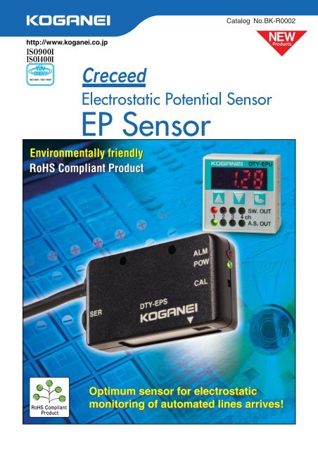
Catalog No.BK-R0002ISO 9001 / ISO 14001<strong>EP</strong> <strong>Sensor</strong>Environmentally friendlyRoHS Compliant ProductOptimum sensor for electrostaticmonitoring of automated lines arrives!
Environmentally friendly RoHS compliant product!Optimum sensor for electrostatic monitoringon production line arrives!Offers electrostatic measurement and constant monitoring on production linedifficult to handle with handy-type measuring instruments.All-in-one configuration achieves lower costs and total space reduction.<strong>EP</strong> <strong>Sensor</strong>Enables electrostatic control on production lineConstant monitoring of invisible static electricity can be performedwithout expending manhours on electrostatic measurement or controls.Electrostatic controls through constant monitoring can be performed inmeasurement locations difficult to reach with handy-type measuringinstruments.Simple function and simple designAll-in-one design gives functions of judgment output and abnormalityoutput to the <strong>EP</strong> <strong>Sensor</strong> unit. Moreover, since it can be connecteddirectly to an external controller unit without passing through anamplifier etc., the unit achieves a total space reduction.Voltage data includes both digital andanalog output, and connection method tocontrol devices can also be selectedStoring history, etc., on a PC can be performed as judgment outputexternally.Judgment output functionIf the voltage setting (threshold) is exceeded, notification is made by asensor LED and voltage comparison output (judgment output).VoltageMAX(Threshold)MIN(Threshold)ONJudgment outputOFFThree operation mode patterns are availableSelectable from the averaged data output mode, actual measured dataoutput mode, and ion balance monitor mode.● Averaged data output modeAverages the measured data and outputs it externally.For the data output cycle, select from 100ms, 200ms, 500ms, and 1s.● Actual measured data output modeOutputs the actual measured data externally.For the data output cycle, select from 100ms, 200ms, 500ms, and 1s.● Ion balance monitor modeMeasures the ion balance of the ionizer.Selectable from either <strong>EP</strong> Monitor or PCsoftware for <strong>EP</strong> <strong>Sensor</strong> setting method<strong>EP</strong> <strong>Sensor</strong> settings can be performed either through the <strong>EP</strong> Monitor orthe PC software. Settings use RS232C communication. Enables confirmation of ionizer performancewith ion balance measurement functionEasy checking of simple ion balance by mountinga monitor plate note .Note: Monitor plate is optional.IonizerMonitor plateMonitor plateFor the distance between theionizer and monitor plate, seethe recommended minimumposition distances set by eachionizer manufacturer.Component bracket availableWith a separately sold component bracket, various mounting directionsbecome possible.With zero calibration function switchThe zero calibration function can be used to adjust the currentmeasured value to 0V.q
<strong>EP</strong> MonitorOne <strong>EP</strong> Monitor can be connected up to 4 <strong>EP</strong><strong>Sensor</strong>s, and used for switching displaysLED indicators and alarm signals availablewhen threshold is exceededIf the setting voltage is exceeded, you can confirm it by the SW.OUT LED andswitch output (judgment output).VoltageUpper limit:MAX(Threshold)Lower limit:MIN(Threshold)ONJudgment outputOFFThe upper and lower limit (threshold MAX, MIN) can bechanged depending on the setting.Application ExamplesCommunication function can be usedto make various parameter settings(measurement distance, upper andlower limit, operation mode, and dataoutput cycle)Support software (free)●Electric potential measurementof wafers, etc.Use the support software forsetting, display, and control.●Electric potentialmeasurement ofwrapping films, etc.●Electric potential measurementof glass substrates, etc.Download the software from the Koganei website.Major characteristics• Can perform displays of <strong>EP</strong> <strong>Sensor</strong> settings andmeasurement data.(Compatible OS: Windows NT, 2000, XP)*Windows is a registered trademark of MicrosoftCorporation.<strong>EP</strong> Monitor Up to 4 <strong>EP</strong> <strong>Sensor</strong>s canbe connected.●Electric potentialmeasurement ofplastic containersand parts, etc.CONTENTSFeatures . . . . . . . . . . . . . . . . . . . . . . . . . . . . KqSafety Precautions . . . . . . . . . . . . . . . . . . . . KrHandling Instructions and Precautions . . . . . Kt<strong>EP</strong> <strong>Sensor</strong> Specifications . . . . . . . . . . . . . . . Ku<strong>EP</strong> <strong>Sensor</strong> Output Circuit and . . . . . . . . . . . . KuCable Signal Table<strong>EP</strong> Monitor Specifications . . . . . . . . . . . . . . . KiInternal Circuit and Wiring Specifications . . . KiOrder Codes . . . . . . . . . . . . . . . . . . . . . . . . . KoDimensions . . . . . . . . . . . . . . . . . . . . . . . . . . K!0Caution Before use, be sure to read the “Safety Precautions” on p.K. p.r.w
Connection PatternsKq Simple configuration<strong>EP</strong> <strong>Sensor</strong>Judgment outputControl circuit•Lamp•Buzzer•PLC, etc.Terminal PC support software for settings(use only for settings)Kw <strong>EP</strong> Monitor connection (with setting from <strong>EP</strong> Monitor)<strong>Sensor</strong> setting communication cable<strong>EP</strong> <strong>Sensor</strong>1ch<strong>EP</strong> MonitorCable (with communication cable)2chExternal control device3chSW14•PLC, PC, etc.4ch Analog signalKe <strong>EP</strong> Monitor connection (setting from PC)<strong>EP</strong> <strong>Sensor</strong>1ch<strong>EP</strong> MonitorCable 2chExternal control device3chSW14•PLC, PC, etc.4ch Analog signalDTY-<strong>EP</strong>P-CA-3LRS232CTerminal PC support software for settings(use only for settings)Kr Status monitoring application<strong>EP</strong> <strong>Sensor</strong>RS232CMonitor device•Voltage display•Data collection•History•Multiple RS232C ports are mounted on the monitor device to enableconnection of multiple <strong>EP</strong> <strong>Sensor</strong>s for centralized monitoring.•Setting is performed from the monitor device.The power supply wiring has been omitted from the above connection pattern illustrations.e
Safety Precautions (<strong>EP</strong> <strong>Sensor</strong>)Always read these precautions carefully before use.Before selecting and using the product, please read all the Safety Precautions carefully to ensure proper product use.The Safety Precautions shown below are to help you use the product safely and correctly, and to prevent injury or damage to you, otherpeople, and assets beforehand.The directions are ranked according to degree of potential danger or damage:“DANGER!”, “WARNING!”, “CAUTION!”, and “ATTENTION!”DANGERWARNINGCAUTIONATTENTIONExpresses situations that can be clearly predicted as dangerous.If the noted danger is not avoided, it could result in death or serious injury.It could also result in damage or destruction of assets.Expresses situations that, while not immediately dangerous, could become dangerous.If the noted danger is not avoided, it could result in death or serious injury.It could also result in damage or destruction of assets.Expresses situations that, while not immediately dangerous, could become dangerous.If the noted danger is not avoided, it could result in light or semi-serious injury.It could also result in damage or destruction of assets.While there is little chance of injury, this content refers to points that should be observed forappropriate use of the product.This product was designed and manufactured as parts for use in General Industrial Machinery.■ In the selection and handling of the equipment, the system designer or other person with fully adequate knowledge and experience shouldalways read the Safety Precautions, Catalog, Owner’s Manual and other literature before commencing operation. Making mistakes in handlingis dangerous.■ The customer should take responsibility to verify that the product is compatible with the customer’s systems. Use the product based on your goodjudgment.■ After reading the Owner’s Manual, Catalog, etc., always place them where they can be easily available for reference to users of this product.■ If transferring or lending the product to another person, always attach the Owner’s Manual, Catalog, etc., to the product where they are easilyvisible, to ensure that the new user can use the product safely and properly.■ The danger, warning, and caution items listed under these “Safety Precautions” do not cover all possible cases. Read the Catalog andOwner’s Manual carefully, and always keep safety first.DANGER● Do not use the product for the purposes listed below:1. Medical equipment related to maintenance or management ofhuman lives or bodies.2. Mechanical devices or equipment designed for the purpose ofmoving or transporting people.3. Critical safety components in mechanical devices.This product has not been planned or designed for purposes that requireadvanced stages of safety. It could cause injury to human life.● Do not use the product in locations with or near dangeroussubstances such as flammable or ignitable substances.It could ignite or burst into flames.● When mounting the product and workpiece, always firmly support andsecure them in place. Dropping or falling the product or improperoperation could result in injury.● Persons who use a pacemaker, etc., should keep a distance of atleast 1 meter away from the product. There is a possibility that thepacemaker will malfunction due to the strong magnet built into theproduct.● Never attempt to remodel the product. It could result in abnormaloperation leading to injury, electric shock, fire, etc.● Never attempt inappropriate disassembly, or assembly of the productrelating to its basic inner construction, or to its performance orfunctions. It could result in injury, electric shock, fire, etc.● Do not splash water on the product. Spraying it with water, washing it,or using it underwater could result in malfunction of the productleading to injury, electric shock, fire, etc.WARNING● Do not use the product in excess of its specification range. Such usecould result in product breakdowns, function stop, damage, ordrastically reduce the operating life.● If using the product in the locations listed below, implement adequateshielding measures.Failure to take these measures may cause erratic operation and leadto equipment damage and/or injuries:1. Locations subject to large electric current or magnetic fields2. Locations with the possibility of exposure to radiation● Design safety circuits and equipment systems so as to avoidequipment damage or personal injury when the machine is shut downdue to an emergency stop, power outages, or other systemabnormalities.● Do not use the same conduit or parallel wiring with power lines andhigh voltage lines. The resulting noise may lead to erratic operation ofthe <strong>EP</strong> <strong>Sensor</strong> and <strong>EP</strong> Monitor.● Always shut off the power supply when performing wiring work. Thereis a possibility of electric shock.● Check the Catalog, etc., to ensure that product wiring is performedcorrectly. Miswiring could result in damage to the <strong>EP</strong> <strong>Sensor</strong> and <strong>EP</strong>Monitor, etc., or in abnormal operation.● When wiring is completed, check that there are no errors in the wiringconnections before switching on the power.● Correctly apply the specified voltage to the <strong>EP</strong> <strong>Sensor</strong> and <strong>EP</strong>Monitor. Applying of the wrong voltage will prevent the equipmentfrom performing its specified functions, and may result in damage orburnout of the product itself.● Do not insert or pull out the connector while the device is powered on.Also, do not apply unnecessary stress to the connector. It could resultin erratic operation of the equipment leading to personal injury,damage to equipment, or electric shock, etc.● Do not touch the terminals and the miscellaneous switches, etc., whilethe device is powered on. There is a possibility of electric shock andabnormal operation.● Avoid scratching the cords of cables, etc.Letting the cords be subject to scratching, excessive bending, pulling,rolling up, or being placed under heavy objects or squeezed betweentwo objects, may result in current leaks or defective continuity thatcould lead to fire, electric shock, or abnormal operation.● Do not throw the product into fire.The product could explode and/or release toxic gases.● Do not sit on the product, place your foot on it, or place other objectson it.Accidents such as falling could result in injury. Dropping or topplingthe product may result in injury, or it might also damage or break it,resulting in abnormal or erratic operation, runaway, etc.● For inspection, maintenance, replacement, or other kinds ofoperations related to the product, always completely turn off thepower supply before beginning.CAUTION● Do not use the product in locations that are subject to direct sunlight(ultraviolet rays), dust, salt, iron powder, high humidity, or in theambient atmospheres that include organic solvents, phosphate estertype hydraulic oil, sulphur dioxide, chlorine gas, acids, etc. It couldlead to an early shutdown of some functions or a sudden degradationof performance, and result in a reduced operating life.● The <strong>EP</strong> <strong>Sensor</strong> and <strong>EP</strong> Monitor use delicate electronic parts inside.When handling, do not strike, drop, or bump the product so that it isnot subjected to excessive shocks. Even if it does not appear to bedamaged, internal parts could be damaged and erratic operationcould occur.● When installing the product, leave room for adequate working spacearound it. Failure to ensure adequate working space will make it moredifficult to conduct daily inspections or maintenance, which couldeventually lead to system shutdown or damage to the product.● Always post an “operations in progress” sign for installations,adjustments, or other operations, to avoid unintentional supplying ofelectrical power, etc. Such accidental supplies may cause electricshock or sudden activation of the product that could result in physicalinjury.r
Handling Instructions and Precautions● When considering the possibility of using this product in situations orenvironments not specifically noted in the Catalog or Owner’s Manual,or in applications where safety is an important requirement such as inan airplane facility, combustion equipment, leisure equipment, safetyequipment, and other places where human life or assets may begreatly affected, take adequate safety precautions such as anapplication with enough margins for ratings and performance or failsafemeasure.Be sure to consult us about such applications.● Always check the Owner’s Manual and other reference materials forproduct wiring.● When handling the product, wear protective gloves, safety glasses,safety shoes, etc., to keep safety.● Perform daily inspections to check that system functions areperforming as required to prevent accidents from happeningbeforehand.● When the product can no longer be used, or is no longer necessary,dispose of it appropriately as industrial waste.● Equipment performance and function can deteriorate over the servicelifetime. Perform daily equipment inspections to check that therequired system functions are being satisfied and to prevent accidentsbefore they happen.● Always observe the following items.1. When using this product into systems, always use genuineKOGANEI parts or compatible parts (recommended parts).When performing maintenance and repairs, always use genuineKOGANEI parts or compatible parts (recommended parts).Always observe the required methods and procedure.2. Never attempt inappropriate disassembly or assembly of the productrelating to basic construction, or its performance or functions.Koganei cannot be responsible if these items are not properly observed.Handling Instructions and PrecautionsWiringATTENTIONOTHERSGeneral precautions1. When using a switching regulator obtained on the market for thepower supply, always ground the frame ground (F.G.) terminal.2. When using equipment (switching regulator, inverter motor, etc.) thatcan become a source of noise around the <strong>EP</strong> <strong>Sensor</strong> mounting area,always ground the equipment frame ground (F.G.) terminal.3. When wiring is completed, check that there are no errors in the wiringconnections.q Alarm LED (red)w Power LED (green)e Calibration switchr Cablet Communicationcable jacky Dust coverZero calibrationBlinks when judgment output is ON, lights upwhen sensor abnormality occursLights up when power supply is ONExecutes zero calibration, outputs reset afterjudgment outputPower and signal wiring connectionCommunication cable connection for settingRubber cover for protection against dust1. For mounting the <strong>EP</strong> <strong>Sensor</strong>, use either the screws provided (M30.5, length 18mm [0.709in.]) or M30.5 screws. Use a tighteningtorque of 0.4N·m [3.5in·lbf]. Be careful when tightening, since overtighteningwill damage the <strong>EP</strong> <strong>Sensor</strong>.2. Always perform grounding. Because measurement of electricpotential uses the ground electric potential as the reference, theelectric potential cannot be accurately measured unless connected toa ground.3. The <strong>EP</strong> <strong>Sensor</strong> body is connected to a ground. Be sure to provideadequate insulation when mounting in a location subject to applyingvoltages.4. Do not touch the detecting portion. Also, do not let high pressure airblow against it. The detecting portion could be damaged.5. Ensure a dust-free environment around the detecting portion.6. If the detecting portion requires cleaning, position the detectingportion so that it faces downward, and blow air at a pressure of0.1MPa [14.5psi] or less from a distance of at least 100mm [3.94in.].7. Where stability in electric potential detection is needed, a wait of atleast 15 minutes after the power supply is switched on before startingoperation is recommended.8. This sensor measures the strength of electric field to calculate thevoltage value. As a result, be aware that the presence of itemscapable of disturbing the electric field (relays, solenoids, metal chips,etc.) near the sensor, or between the sensor and the item beingmeasured, could affect the measurement value.1. Zero calibration is a function for adjusting the reference electricpotential where the measured value is 0V. The 0V electric potential isrecorded at space where no metal plate or charged object isconnected to the ground.2. When the power supply is connected and the operation mode isswitched between the ion balance monitor mode and averaged dataoutput mode, or between the ion balance monitor mode and actualmeasured data output mode, the reference electric potential isautomatically set to the ground electric potential connected to the body.Major parts and functions of <strong>EP</strong> MonitorqtytOthers1. Check power supply fluctuations to ensure that power input does notexceed the rated value.2. Avoid use during the transient period (0.5s) when the power isswitched on.3. Do not use needle tips or other sharp points to perform key operation.Major parts and functions of <strong>EP</strong> <strong>Sensor</strong>rtySERDTY-<strong>EP</strong>SMounting holesqALMPOWCALDetecting portionwerweNameq LED display (red)w Switch outputindicator (red) e Autoscanindicator (green)DescriptionDisplays the detected electric potential value,setting contents, and error contentLights up when switch output is ONChannel displaying current electric potentiallights upr UP key ( ) Used when adjusting setting value upwardt DOWN key ( ) Used when adjusting setting value downwardy Mode key ( ) Used for all types of settings1. Since miswiring in the <strong>EP</strong> <strong>Sensor</strong>, or in the power supply, switch, andcommunication cable, can damage both the <strong>EP</strong> Monitor and <strong>EP</strong><strong>Sensor</strong>, always check the wiring before switching on the power.2. The setting conditions are written to E<strong>EP</strong>ROM and saved. Be awarethat E<strong>EP</strong>ROM has a finite lifetime, with a write guarantee times up to100,000 times.
Mounting and wiring<strong>Sensor</strong> and connector connection procedureConnect the <strong>EP</strong> <strong>Sensor</strong> DTY-<strong>EP</strong>S and the mini clamp connector. Followthe procedure below to perform the connections.1. Check that the connector cover (the part where lead wire is inserted)is protruding from the connector body.Attaching and removing of the <strong>EP</strong> <strong>Sensor</strong>, and thepower supply, switch, and communication cableLock lever<strong>EP</strong> <strong>Sensor</strong>DTY-<strong>EP</strong>S2ch1ch3ch4chConnector for4 <strong>EP</strong> <strong>Sensor</strong>sIt cannot be used if it’s flat and placed at the same level against thebody.2. Arrange the <strong>EP</strong> <strong>Sensor</strong> cable into the required form.Since the insulation on the tip of the lead wire has been peeled offand soldered, cut the wires at about 10mm [0.39in.] from the tip sothat it does not protrude from the insulation.CutLock leverPower supply, switch,and communication cableDTY-<strong>EP</strong>P--Connector for powersupply, switch, andcommunication cableTo mount the <strong>EP</strong> <strong>Sensor</strong> and the power supply, switch, andcommunication cable, align the lock lever position as shown in the figure,and push until the lock hooks on the controller-side connector.To remove, push down hard on the lock lever, take the connector and pullit out. At this time, be careful to avoid applying unnecessary force on thelead wires.Attaching the panel mounting parts and protective front coverPanel plateCautionGround terminalCaution: Prepare any unused lead wires so that they will not short circuit.3. Follow the instructions in the table to insert the lead wires into thehole in the connector cover. Look through the top of the semitransparentcover to check that the lead wires have been firmlyinserted all the way to the back. (Insertion is about 9mm [0.35in.].)Use caution in making the connections, since switching on the powerwith mistakes in the connections will damage the <strong>EP</strong> <strong>Sensor</strong> and <strong>EP</strong>Monitor.No. on the connector1234Signal name<strong>EP</strong> <strong>Sensor</strong> power supply ()<strong>EP</strong> <strong>Sensor</strong> analog output<strong>EP</strong> <strong>Sensor</strong> power supply (0V)<strong>EP</strong> <strong>Sensor</strong> abnormalityColor of lead wire<strong>EP</strong> <strong>Sensor</strong> yellow/red wire<strong>EP</strong> <strong>Sensor</strong> white/red wire<strong>EP</strong> <strong>Sensor</strong> yellow/black wire<strong>EP</strong> <strong>Sensor</strong> gray/red wireMountingbodyProtectivefront cover(sold separately)4)1)2)Mounting holder3)<strong>EP</strong> Monitor1) Insert the mountingbody from the front ofthe panel hole.2) Insert the sensorcontroller from theback of the mountingbody.3) From the back of theposition in 2), placethe mounting holderon the mounting bodygroove, and insert it.Yellow/red wireWhite/red wireGroove on panel mounting body4) Set the separatelysold protective frontcover in place.Yellow/black wireGray/red wire4 3 2 1<strong>EP</strong> <strong>Sensor</strong> For removal, follow the aboveprocedure in reverse, using ascrewdriver or other tool to removethe mounting holder.Attaching the mounting bracket<strong>EP</strong> <strong>Sensor</strong>4. Taking care to avoid letting the lead wire slip out from the connector,use pliers or some other hand tool to crimp the cover and connectorbody, and push the cover into the connector body.Limit the crimping force to 980.7N [220lbf.] or less.When the cover is flat and placed at the same level against theconnector body, the connection is complete.5. Check one more time that the wiring is correct.2-M2.60.45Depth 6 [0.236in.](Mounting thread)Hex sockethead screw(Provided withmounting bracket)Mounting bracketPSU-BRUse the hex socket headscrews (M2.60.45,length 5mm [0.197in.]) tomount the mountingbracket into the mountingholes on the back of thesensor controller.The tightening torqueshould be 0.32Nm[2.83inlbf].y
<strong>EP</strong> <strong>Sensor</strong> SpecificationsModelItemVoltageCurrentMeasurement rangeAccuracyMethodJudgment outputApplied voltageSink currentMethod<strong>Sensor</strong> abnormality outputApplied voltageSink currentOutput voltageAnalog outputZero pointCommunication I/FSampling periodData output cycleInput/output response time (for averaged data output mode) Note 1Temperature characteristicsOperating temperature rangeOperating humidity rangeStorage temperature rangeCable lengthCase materialOuter dimensionsMassAccessoriesDTY-<strong>EP</strong>S3m [9.84ft.]Notes: 1. Response time in the actual measured data output mode is 100ms or less.2. Does not include the mass of the cable.Remark: If not specified, the measurement condition assumes an ambient temperature of 25°C.Measurement distance and measurement voltage rangeMeasurement distanceIon balance mode510mm [0.200.39in.]1120mm [0.430.79in.]2130mm [0.831.18in.]3140mm [1.221.57in.]4150mm [1.611.97in.]Maximum voltage1kV5kV10kV15kV20kV20kV24VDC10%Max. 50mA550mm [0.201.97in.]5%rdg 2digNPN transistor open collector30VDC or less20mA or lessNPN transistor open collector30VDC or less20mA or less15V3VConformity with RS232CApproximately 10ms100ms, 200ms, 500ms, 1sMaximum of double the data output cycle0.5% F.S./°C040°C [32104°F]80% RH or less (no condensation)–2060°C [–4140°F]<strong>EP</strong> <strong>Sensor</strong> Output Circuit and Cable Signal TableDTY-<strong>EP</strong>S-10L10m [32.8ft.]Conductive ABS resin61.2(W)mm34.2(H)mm15.0(D)mmApproximately 30g [1.06oz.] Note 2L shaped mounting bracket 1 pec. (with 2 mounting screws)Resolution2V10V20V30V40V40VMain circuit<strong>EP</strong> <strong>Sensor</strong>DTr1Tr2CableColor of lead wire(Yellow/red)24VLoad(Orange/red) CP20mA MAX Load(Gray/red) ALM20mA MAX(Yellow/black) 0V(Orange/black) TXD(Gray/black) RXD(White/red) SA(White/black) AG24VDC10Always use connectors suitedto the connecting devices.External devices withcommunicationfunctionsExternal devices withanalog inputCable signal tableNo.123456789ColorOrange/blackOrange/redGray/blackGray/redWhite/blackWhite/redYellow/blackYellow/redGreenSignal nameTXDCPRXDALMAGSA0V24VFGDescriptionCommunicating and sending dataVoltage comparison output(Judgment output)Communicating and receiving data<strong>Sensor</strong> abnormalityAnalog GNDAnalog outputPower supply GNDPower supply24VFrame GNDSER(Green) FGDTY-<strong>EP</strong>P-CA orDTY-<strong>EP</strong>P-CC1RXD2TXD3SGPC for settings,andsupport softwareor DTY-<strong>EP</strong>USER jack signal tableNo. Signal name1RXD2TXD3SGDescriptionCommunicating and receiving dataCommunicating and sending dataSignal GND (Power supply GND)u
<strong>EP</strong> Monitor SpecificationsItemVoltageCurrent<strong>Sensor</strong> inputSwitch outputModelNumber of inputsVoltage rangeMaximum applied voltageNumber of outputsMethodApplied voltageCurrentVoltage dropDTY-<strong>EP</strong>U24VDC10%100mA MAX Note 14 channels15VDC5.3V4NPN open collector30VDC MAX50mA MAX0.3V MAX/At 5mAElectric potential display7-segment LED 4 digits, Unit: kV (with decimal point) Note 2Switch output check displayRed LED 4 pcs.Input channel check displayGreen LED 4 pcs.Setting key switchPushbutton type, 3 keys (UP, DOWN, MODE)Communication I/FConformity with RS232COperating temperature range–1050°C [14122°F]Operating humidity range3580%RHStorage temperature range–2080°C [–4176°F]Case materialPBTOuter dimensions40(W)mm40(H)mm32(D)mmMassApproximately 45g [1.59oz.]AccessoriesMini clamp wire mount plug 4 pcs.Notes: 1. At <strong>EP</strong> <strong>Sensor</strong> in unconnected state2. When in the ion balance monitor mode, the unit is V (no decimal point).Internal Circuit and Wiring Specifications<strong>EP</strong> <strong>Sensor</strong>1chSER<strong>EP</strong> <strong>Sensor</strong>2chSER<strong>EP</strong> <strong>Sensor</strong>3chSERMain circuitMain circuitMain circuit(Yellow/red)24V(White/red) SA(Yellow/black) 0V(Gray/red) ALM(Yellow/red)24V(White/red) SA(Yellow/black) 0V(Gray/red) ALM(Yellow/red)24V(White/red) SA(Yellow/black) 0V(Gray/red) ALMMain circuit<strong>EP</strong> MonitorDTr1Tr2Tr3Tr4ZD1ZD2ZD3ZD4Power and switchoutput cableCommunicationNotecable(Red)VLoad(White) SW150mA MAX Load(Green) SW250mA MAXLoad(Yellow) SW350mA MAXLoad(Brown) SW450mA MAX(Black) 0V0VRXDTXDColor of lead wire24VDC10Note: Power supply, switch, andcommunication cableDTY-<strong>EP</strong>P-CC-L is available.<strong>EP</strong> <strong>Sensor</strong>4chSERMain circuit(Yellow/red)24V(White/red) SA(Yellow/black) 0V(Gray/red) ALMRTSCTSConnect to each <strong>EP</strong> sensor, and setInternal circuitExternal connectionexampleNote: When the cable is extended, be aware that voltage will drop due to resistance in the cable.Key to codes D: Reverse current protection diode for power supplyZD1ZD4: Zener diode for surge voltage absorptionTr1 Tr4: NPN output transistori
Order Codes■ <strong>EP</strong> <strong>Sensor</strong>DTY<strong>EP</strong>S<strong>EP</strong> <strong>Sensor</strong> seriesAdditional parts (to be ordered separately)Component bracketMonitor plateCable lengthBlank: 3m [9.84ft.]10L: 10m [32.8ft.] Note: The <strong>EP</strong> <strong>Sensor</strong> is provided with an L shaped bracket (with 2 mountingscrews) for mounting.Communication cable for <strong>EP</strong> <strong>Sensor</strong> (3m)DTY-<strong>EP</strong>P-BR2 DTY-<strong>EP</strong>P-MP DTY-<strong>EP</strong>P-CA-3L■ <strong>EP</strong> MonitorDTY<strong>EP</strong>UComes with 4 pcs. mini clampwire mount plugs.Power supply, switch, and communication cableBlank: No cable3L: With 3m [9.84ft.] cable 10L: With 10m [32.8ft.] cable 3LD: With 3m [9.84ft.] cable (with communication cable) 10LD: With 10m [32.8ft.] cable (with communication cable) Protective front cover NoteBlank: Without protective front coverC: With protective front coverMounting partBlank: NoneB: With mounting bracketP: With panel mounting partsNote: The protective front cover can only be selected whenthe panel mounting parts are selected.Additional parts (to be ordered separately)Power supply, switch, and communication cableDTY <strong>EP</strong>PCommunication cableCB: No communication cableCC: With communication cableCable length13L: 3m [9.84ft.]10L: 10m [32.8ft.]Mounting bracketPSU-BRPanel mountingpartsPM100Protective frontcoverKB100Mini clamp wire mount plugPSU-Mo
Dimensions (mm)<strong>EP</strong> <strong>Sensor</strong>● DTY-<strong>EP</strong>S-Cable length 3m or 10m0.1 (Ground washer)Ground washer(Ground terminal)LED (red)LED (green)Detecting portionBracket (supplied)Ground terminalM30.5 length 18 mounting screw, plain washer (with 2 pcs. each)Component bracket● DTY-<strong>EP</strong>P-BR2(With 2 pcs. M40.7 length 10, hex socket head screws)Detecting positionCan be moved to any desired angle<strong>EP</strong> <strong>Sensor</strong> (DTY-<strong>EP</strong>S)Can be moved toany desired angleDetecting positionMonitor plate● DTY-<strong>EP</strong>P-MP<strong>EP</strong> <strong>Sensor</strong> (DTY-<strong>EP</strong>S)Communication cable for <strong>EP</strong> <strong>Sensor</strong>● DTY-<strong>EP</strong>P-CA-3LD-sub 9-pin female with case!0
Dimensions (mm)<strong>EP</strong> Monitor● DTY-<strong>EP</strong>U-Mini clamp wire mount plug(4 pcs. supplied)Wiring label enlarged view 4-digit LED pressure displayMode buttonWiring labelConnctors for 4-sensor heads2-M2.60.45 Depth 6(Mounting thread) 4-switch output indicatorsLED (red)4-auto scanchannel indicatorsLED (green)DOWN buttonUP buttonConnector for powersupply, switch, andcommunication cablePower Supply and Switch Cable● DTY-<strong>EP</strong>P-CB-LPower supply andswitch output cable(6 leads)Mounting Bracket● PSU-BRModelDTY-<strong>EP</strong>P-CB-3LDTY-<strong>EP</strong>P-CB-10LWith 2 hex socket head screwsM2.60.45 length 5Power Supply, Switch, and Communication Cable● DTY-<strong>EP</strong>P-CC-LModelDTY-<strong>EP</strong>P-CC-3LDTY-<strong>EP</strong>P-CC-10LPower supply andswitch output cable(6 leads) Communication cable(3 leads)!1
Panel Mounting Parts Installed Diagram● DTY-<strong>EP</strong>U-P (Panel mounting parts installed diagram)● Machining dimensions for the <strong>EP</strong> Monitor mounting hole Protective front cover● KB100Notes: 1. Use a mounting panel thickness of 1 to 3.2mm.2. If mounting in adjacent positions, make the interval larger thanthe value shown in the figure above.3. Conforms to DIN43700.!2
!3MEMO
Limited WarrantyKOGANEI CORP. warrants its products to be free from defectsin material and workmanship subject to the following provisions.Warranty PeriodKoganeiResponsibilityLimitationsThe warranty period is 180 days from the dateof delivery.If a defect in material or workmanship is foundduring the warranty period, KOGANEI CORP.will replace any part proved defective undernormal use free of charge and will provide theservice necessary to replace such a part.This warranty is in lieu of all other warranties,•expressed or implied, and is limited to theoriginal cost of the product and shall notinclude any transportation fee, the cost ofinstallation or any liability for direct, indirector consequential damage or delay resultingfrom the defects.KOGANEI CORP. shall in no way be liable or responsible for•injuries or damage to persons or property arising out of theuse or operation of the manufacturer’s product.•This warranty shall be void if the engineered safety devicesare removed, made inoperative or not periodically checked forproper functioning.Any operation beyond the rated capacity, any improper use or•application, or any improper installation of the product, or anysubstitution upon it with parts not furnished or approved byKOGANEI CORP., shall void this warranty.•This warranty covers only such items supplied by KOGANEICORP. The products of other manufacturers are covered only bysuch warranties made by those original manufacturers, eventhough such items may have been included as the components.The specifications are subject to change without notice.!4
Related catalogIONIZER resolving problems caused by static charges.Wide variety of IONIZERs, which meet the need ofpinpoint to wide-area static charge removal, areprovided.Static Electricity Removing Unit IONIZERCatalog No.BK-R0001URL http://www.koganei.co.jpE-mail: overseas@koganei.co.jpOVERSEAS D<strong>EP</strong>ARTMENT3-11-28, Midori-cho, Koganei City, Tokyo 184-8533, JapanTel: 042-383-7271 Fax: 042-383-7276MICHIGAN R<strong>EP</strong>RESENTATIVE OFFICE5070 East N Ave., Kalamazoo, Michigan, 49048, U.S.A.Tel: 269-388-8769 Fax: 269-388-8771SHANGHAI KOGANEI INTERNATIONAL TRADING CORPORATIONRoom 2606-2607, Tongda Venture Building No.1, Lane 600,Tianshan Road, Shanghai, 200051, ChinaTel: 021-6145-7313 Fax: 021-6145-7323KOGANEI-PORNCHAI CO., LTD.89/174 Moo 3, Vibhavadee Rangsit Road, Talad Bangkhen, Laksi, Bangkok, 10210, ThailandTel: 02-551-4025 Fax: 02-551-40153/’07 30 BPBP©KOGANEI CORP. PRINTED IN JAPANRECYCLED PAPER


