X9221 Dual E2POT⢠Nonvolatile Digital Potentiometer Terminal ...
X9221 Dual E2POT⢠Nonvolatile Digital Potentiometer Terminal ...
X9221 Dual E2POT⢠Nonvolatile Digital Potentiometer Terminal ...

You also want an ePaper? Increase the reach of your titles
YUMPU automatically turns print PDFs into web optimized ePapers that Google loves.
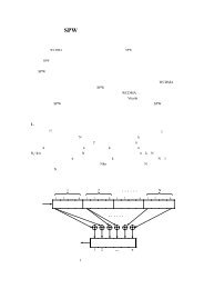
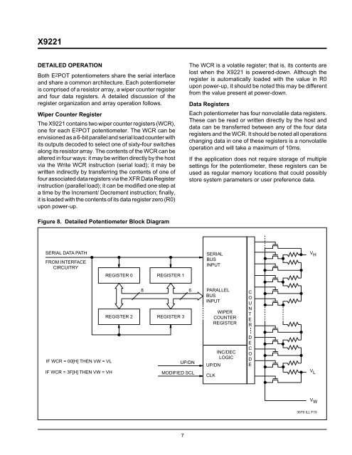
<strong>X9221</strong>DETAILED OPERATIONBoth E2POT potentiometers share the serial interfaceand share a common architecture. Each potentiometeris comprised of a resistor array, a wiper counter registerand four data registers. A detailed discussion of theregister organization and array operation follows.Wiper Counter RegisterThe <strong>X9221</strong> contains two wiper counter registers (WCR),one for each E2POT potentiometer. The WCR can beenvisioned as a 6-bit parallel and serial load counter withits outputs decoded to select one of sixty-four switchesalong its resistor array. The contents of the WCR can bealtered in four ways: it may be written directly by the hostvia the Write WCR instruction (serial load); it may bewritten indirectly by transferring the contents of one offour associated data registers via the XFR Data Registerinstruction (parallel load); it can be modified one step ata time by the Increment/ Decrement instruction; finally,it is loaded with the contents of its data register zero (R0)upon power-up.The WCR is a volatile register; that is, its contents arelost when the <strong>X9221</strong> is powered-down. Although theregister is automatically loaded with the value in R0upon power-up, it should be noted this may be differentfrom the value present at power-down.Data RegistersEach potentiometer has four nonvolatile data registers.These can be read or written directly by the host anddata can be transferred between any of the four dataregisters and the WCR. It should be noted all operationschanging data in one of these registers is a nonvolatileoperation and will take a maximum of 10ms.If the application does not require storage of multiplesettings for the potentiometer, these registers can beused as regular memory locations that could possiblystore system parameters or user preference data.Figure 8. Detailed <strong>Potentiometer</strong> Block DiagramSERIAL DATA PATHFROM INTERFACECIRCUITRYSERIALBUSINPUTV HREGISTER 0 REGISTER 18 6REGISTER 2 REGISTER 3PARALLELBUSINPUTWIPERCOUNTERREGISTERCOUNTERIF WCR = 00[H] THEN VW = VLIF WCR = 3F[H] THEN VW = VHUP/DNMODIFIED SCLINC/DECLOGICUP/DNCLKDECODEV LV W3079 ILL F157