TJA1054 Fault-tolerant CAN transceiver
TJA1054 Fault-tolerant CAN transceiver
TJA1054 Fault-tolerant CAN transceiver

You also want an ePaper? Increase the reach of your titles
YUMPU automatically turns print PDFs into web optimized ePapers that Google loves.
INTEGRATED CIRCUITSDATA SHEET<strong>TJA1054</strong><strong>Fault</strong>-<strong>tolerant</strong> <strong>CAN</strong> <strong>transceiver</strong>Product specificationSupersedes data of 1999 Feb 11File under Integrated Circuits, IC182001 Nov 20
Philips SemiconductorsProduct specification<strong>Fault</strong>-<strong>tolerant</strong> <strong>CAN</strong> <strong>transceiver</strong><strong>TJA1054</strong>FEATURESOptimized for in-car low-speed communication• Baud rate up to 125 kBaud• Up to 32 nodes can be connected• Supports unshielded bus wires• Very low ElectroMagnetic Emission (EME) due tobuilt-in slope control function and a very good matchingof the <strong>CAN</strong>L and <strong>CAN</strong>H bus outputs• Good ElectroMagnetic Immunity (EMI) in normaloperating mode and in low power modes• Fully integrated receiver filters• Transmit Data (TxD) dominant time-out function.Bus failure management• Supports single-wire transmission modes with groundoffset voltages up to 1.5 V• Automatic switching to single-wire mode in the event ofbus failures, even when the <strong>CAN</strong>H bus wire isshort-circuited to V CC• Automatic reset to differential mode if bus failure isremoved• Full wake-up capability during failure modes.GENERAL DESCRIPTIONThe <strong>TJA1054</strong> is the interface between the protocolcontroller and the physical bus wires in a Controller AreaNetwork (<strong>CAN</strong>). It is primarily intended for low-speedapplications up to 125 kBaud in passenger cars. Thedevice provides differential receive and transmit capabilitybut will switch to single-wire transmitter and/or receiver inerror conditions.The <strong>TJA1054</strong>T is pin and downwards compatible with thePCA82C252T and the TJA1053T. This means that thesetwo devices can be replaced by the <strong>TJA1054</strong>T withretention of all functions.The most important improvements of the <strong>TJA1054</strong> withrespect to the PCA82C252 and the TJA1053 are:• Very low EME due to a very good matching of the <strong>CAN</strong>Land <strong>CAN</strong>H output signals• Good EMI, especially in low power modes• Full wake-up capability during bus failures• Extended bus failure management includingshort-circuit of the <strong>CAN</strong>H bus line to V CC• Support for easy system fault diagnosis• Two-edge sensitive wake-up input signal via pin WAKE.Protections• Bus pins short-circuit safe to battery and to ground• Thermally protected• Bus lines protected against transients in an automotiveenvironment• An unpowered node does not disturb the bus lines.Support for low power modes• Low current sleep and standby mode with wake-up viathe bus lines• Power-on reset flag on the output.ORDERING INFORMATIONTYPEPACKAGENUMBER NAME DESCRIPTION VERSION<strong>TJA1054</strong>T SO14 plastic small outline package; 14 leads; body width 3.9 mm SOT108-1<strong>TJA1054</strong>U − bare die; 2000 × 2830 × 375 µm −2001 Nov 20 2
Philips SemiconductorsProduct specification<strong>Fault</strong>-<strong>tolerant</strong> <strong>CAN</strong> <strong>transceiver</strong><strong>TJA1054</strong>QUICK REFERENCE DATASYMBOL PARAMETER CONDITIONS MIN. TYP. MAX. UNITV CC supply voltage on pin V CC 4.75 − 5.25 VV BAT battery voltage on pin BAT no time limit −0.3 − +40 Voperating mode 5.0 − 27 Vload dump − − 40 VI BAT battery current on pin BAT Sleep mode; V CC =0V; − 30 50 µAV BAT =12VV <strong>CAN</strong>H <strong>CAN</strong>H bus line voltage V CC = 0 to 5.5 V; V BAT ≥ 0V; −40 − +40 Vno time limitV <strong>CAN</strong>L <strong>CAN</strong>L bus line voltage V CC = 0 to 5.5 V; V BAT ≥ 0V;no time limit−40 − +40 V∆V <strong>CAN</strong>H∆V <strong>CAN</strong>L<strong>CAN</strong>H bus line transmittervoltage dropI <strong>CAN</strong>H = −40 mA − − 1.4 V<strong>CAN</strong>L bus line transmitter I <strong>CAN</strong>L =40mA − − 1.4 Vvoltage dropt PD(L) propagation delay TXD (LOW)− 1 − µsto RXD (LOW)t r bus line output rise time between 10% and 90%; − 0.6 − µsC1 = 10 nF; see Fig.5t f bus line output fall time between 90% and 10%; − 0.3 − µsC1 = 1 nF; see Fig.5T vj virtual junction temperature −40 − +150 °C2001 Nov 20 3
Philips SemiconductorsProduct specification<strong>Fault</strong>-<strong>tolerant</strong> <strong>CAN</strong> <strong>transceiver</strong><strong>TJA1054</strong>BLOCK DIAGRAMhandbook, full pagewidthBATV CC1014INHWAKESTBENTXD17562V CCTIMERWAKE-UPSTANDBYCONTROLTEMPERATUREPROTECTIONDRIVER911128RTL<strong>CAN</strong>H<strong>CAN</strong>LRTHV CC<strong>TJA1054</strong>ERR4FAILURE DETECTORPLUS WAKE-UPPLUS TIME-OUTV CCFILTERRXD3RECEIVERFILTER13MGL421GNDFig.1 Block diagram.2001 Nov 20 4
Philips SemiconductorsProduct specification<strong>Fault</strong>-<strong>tolerant</strong> <strong>CAN</strong> <strong>transceiver</strong><strong>TJA1054</strong>PINNINGSYMBOL PIN DESCRIPTIONINH 1 inhibit output for switching an external voltage regulator if a wake-up signal occursTXD 2 transmit data input for activating the driver to the bus linesRXD 3 receive data output for reading out the data from the bus linesERR 4 error, wake-up and power-on indication output; active LOW in normal operating mode when the bushas a failure, and in low power modes (wake-up signal or in power-on standby)STB 5 standby digital control signal input (active LOW); together with the input signal on pin EN this inputdetermines the state of the <strong>transceiver</strong> (in normal and low power modes); see Table 2 and Fig.3EN 6 enable digital control signal input; together with the input signal on pin STB this input determinesthe state of the <strong>transceiver</strong> (in normal and low power modes); see Table 2 and Fig.3WAKE 7 local wake-up signal input (active LOW); both falling and rising edges are detectedRTH 8 termination resistor connection; in case of a <strong>CAN</strong>H bus wire error the line is terminated with apredefined impedanceRTL 9 termination resistor connection; in case of a <strong>CAN</strong>L bus wire the line is terminated with a predefinedimpedanceV CC 10 supply voltage<strong>CAN</strong>H 11 HIGH-level <strong>CAN</strong> bus line<strong>CAN</strong>L 12 LOW-level <strong>CAN</strong> bus lineGND 13 groundBAT 14 battery voltage connectionhandbook, halfpageINH114 BATTXD213GNDRXD312<strong>CAN</strong>LERR4<strong>TJA1054</strong>T11<strong>CAN</strong>HSTB510V CCEN69RTLWAKE78RTHMGL422Fig.2 Pin configuration.2001 Nov 20 5
Philips SemiconductorsProduct specification<strong>Fault</strong>-<strong>tolerant</strong> <strong>CAN</strong> <strong>transceiver</strong><strong>TJA1054</strong>FUNCTIONAL DESCRIPTIONThe <strong>TJA1054</strong> is the interface between the <strong>CAN</strong> protocolcontroller and the physical wires of the <strong>CAN</strong> bus(see Fig.7). It is primarily intended for low speedapplications, up to 125 kBaud, in passenger cars. Thedevice provides differential transmit capability to the <strong>CAN</strong>bus and differential receive capability to the <strong>CAN</strong>controller.To reduce EME, the rise and fall slopes are limited. Thisallows the use of an unshielded twisted pair or a parallelpair of wires for the bus lines. Moreover, the devicesupports transmission capability on either bus line if one ofthe wires is corrupted. The failure detection logicautomatically selects a suitable transmission mode.In normal operating mode (no wiring failures) thedifferential receiver is output on pin RXD (see Fig.1).The differential receiver inputs are connected topins <strong>CAN</strong>H and <strong>CAN</strong>L through integrated filters.The filtered input signals are also used for the single-wirereceivers. The receivers connected to pins <strong>CAN</strong>Hand <strong>CAN</strong>L have threshold voltages that ensure amaximum noise margin in single-wire mode.A timer function (TxD dominant time-out function) hasbeen integrated to prevent the bus lines from being driveninto a permanent dominant state (thus blocking the entirenetwork communication) due to a situation in whichpin TXD is permanently forced to a LOW level, caused bya hardware and/or software application failure.If the duration of the LOW level on pin TXD exceeds acertain time, the transmitter will be disabled. The timer willbe reset by a HIGH level on pin TXD.Failure detectorThe failure detector is fully active in the normal operatingmode. After the detection of a single bus failure thedetector switches to the appropriate mode (see Table 1).The differential receiver threshold voltage is set at −3.2 Vtypical (V CC = 5 V). This ensures correct reception with anoise margin as high as possible in the normal operatingmode and in the event of failures 1, 2, 5 and 6a. Thesefailures, or recovery from them, do not destroy ongoingtransmissions. The output drivers remain active, thetermination does not change and the receiver remains indifferential mode (see Table 1).Failures 3, 3a and 6 are detected by comparatorsconnected to the <strong>CAN</strong>H and <strong>CAN</strong>L bus lines.Failures 3 and 3a are detected in a two-step approach.If the <strong>CAN</strong>H bus line exceeds a certain voltage level, thedifferential comparator signals a continuous dominantcondition. Because of inter-operability reasons with thepredecessor products PCA82C252 and TJA1053, after afirst time-out the <strong>transceiver</strong> switches to single wireoperation through <strong>CAN</strong>H. If the <strong>CAN</strong>H bus line is stillexceeding the <strong>CAN</strong>H detection voltage for a secondtime-out, the <strong>TJA1054</strong> switches to <strong>CAN</strong>L operation; the<strong>CAN</strong>H driver is switched off and the RTH bias changes tothe pull-down current source. The time-outs (delays) areneeded to avoid false triggering by external RF fields.Table 1Bus failuresFAILUREDESCRIPTIONTERMINATION<strong>CAN</strong>H (RTH)TERMINATION<strong>CAN</strong>L (RTL)Notes1. A weak termination implies a pull-down current source behaviour of 75 µA typical.2. A weak termination implies a pull-up current source behaviour of 75 µA typical.<strong>CAN</strong>HDRIVER<strong>CAN</strong>LDRIVERRECEIVERMODE1 <strong>CAN</strong>H wire interrupted on on on on differential2 <strong>CAN</strong>L wire interrupted on on on on differential3 <strong>CAN</strong>H short-circuited to battery weak; note 1 on off on <strong>CAN</strong>L3a <strong>CAN</strong>H short-circuited to V CC weak; note 1 on off on <strong>CAN</strong>L4 <strong>CAN</strong>L short-circuited to ground on weak; note 2 on off <strong>CAN</strong>H5 <strong>CAN</strong>H short-circuited to ground on on on on differential6 <strong>CAN</strong>L short-circuited to battery on weak; note 2 on off <strong>CAN</strong>H6a <strong>CAN</strong>L short-circuited to V CC on on on on differential7 <strong>CAN</strong>L and <strong>CAN</strong>H mutuallyshort-circuitedon weak; note 2 on off <strong>CAN</strong>H2001 Nov 20 6
Philips SemiconductorsProduct specification<strong>Fault</strong>-<strong>tolerant</strong> <strong>CAN</strong> <strong>transceiver</strong><strong>TJA1054</strong>Failure 6 is detected if the <strong>CAN</strong>L bus line exceeds itscomparator threshold for a certain period of time. Thisdelay is needed to avoid false triggering by external RFfields. After detection of failure 6, the reception is switchedto the single wire mode through <strong>CAN</strong>H; the <strong>CAN</strong>L driver isswitched off and the RTL bias changes to the pull-upcurrent source.Recovery from failures 3, 3a and 6 is detectedautomatically after reading a consecutive recessive levelby corresponding comparators for a certain period of time.Failures 4 and 7 initially result in a permanent dominantlevel on pin RXD. After a time-out the <strong>CAN</strong>L driver isswitched off and the RTL bias changes to the pull-upcurrent source. Reception continues by switching to thesingle-wire mode via pins <strong>CAN</strong>H or <strong>CAN</strong>L. Whenfailures 4 or 7 are removed, the recessive bus levels arerestored. If the differential voltage remains below therecessive threshold level for a certain period of time,reception and transmission switch back to the differentialmode.If any of the wiring failures occur, the output signal onpin ERR will be set to LOW. On error recovery, the outputsignal on pin ERR will be set to HIGH again. In case of aninterrupted open bus wire, this failure will be detected andsignalled only if there is an open wire between thetransmitting and receiving node(s). Thus, during open wirefailures, pin ERR typically toggles.During all single-wire transmissions, EMC performance(both immunity and emission) is worse than in thedifferential mode. The integrated receiver filters suppressany HF noise induced into the bus wires. The cut-offfrequency of these filters is a compromise betweenpropagation delay and HF suppression. In single-wiremode, LF noise cannot be distinguished from the requiredsignal.Low power modesThe <strong>transceiver</strong> provides three low power modes whichcan be entered and exited via pins STB and EN(see Table 2 and Fig.3).The Sleep mode is the mode with the lowest powerconsumption. Pin INH is switched to high-impedance fordeactivation of the external voltage regulator. Pin <strong>CAN</strong>L isbiased to the battery voltage via pin RTL. If the supplyvoltage is provided, pins RXD and ERR will signal thewake-up interrupt.The standby mode operates in the same way as the Sleepmode but with a HIGH level on pin INH.Table 2Normal operating and low power modesMODEGoto-sleepcommandPINSTBPINENLOW HIGH wake-up interruptsignal;notes 1 and 2Sleep LOW LOW (3)Standby LOW LOWPower-onstandbyNormaloperatingHIGH LOW V BAT power-on flag;notes 1 and 4PIN ERR PIN RXD PIN RTLSWITCHEDLOW HIGH LOW HIGH TOwake-upinterrupt signal;notes 1 and 2wake-upinterrupt signal;notes 1 and 2HIGH HIGH error flag no error flag dominantreceived datarecessivereceived dataNotes1. If the supply voltage V CC is present.2. Wake-up interrupts are released when entering normal operating mode.3. In case the goto-sleep command was used before. When V CC drops pin EN will become LOW, but due to the fail-safefunctionality this does not effect the internal functions.4. V BAT power-on flag will be reset when entering normal operating mode.V BATV BATV CC2001 Nov 20 7
Philips SemiconductorsProduct specification<strong>Fault</strong>-<strong>tolerant</strong> <strong>CAN</strong> <strong>transceiver</strong><strong>TJA1054</strong>The power-on standby mode is the same as the standbymode, however, in this mode the battery power-on flag isshown on pin ERR instead of the wake-up interrupt signal.The output on pin RXD will show the wake-up interrupt.This mode is only for reading out the power-on flag.Wake-up requests are recognized by the <strong>transceiver</strong>through two possible channels:• The bus lines for remote wake-up• Pin WAKE for local wake-up.In order to wake-up the <strong>transceiver</strong> remotely through thebus lines, a filter mechanism is integrated. Thismechanism makes sure that noise and any present busfailure conditions do not result into an erroneous wake-up.Because of this mechanism it is not sufficient to simply pullthe <strong>CAN</strong>H or <strong>CAN</strong>L bus lines to a dominant level for acertain time. To guarantee a successful remote wake-upunder all conditions, a message frame with a dominantphase of at least the maximum specified t <strong>CAN</strong>H or t <strong>CAN</strong>L init is required.A local wake-up through pin WAKE is detected by a risingor falling edge with a consecutive level with the maximumspecified t WAKE .On a wake-up request the <strong>transceiver</strong> will set the output onpin INH to HIGH which can be used to activate the externalsupply voltage regulator.If V CC is present the wake-up request can be read on theERR or RXD outputs, so the external microcontroller canactivate the <strong>transceiver</strong> (switch to normal operating mode)via pins STB and EN.To prevent a false remote wake-up due to transients orRF fields, the wake-up voltage levels have to bemaintained for a certain period of time. In the low powermodes the failure detection circuit remains partly active toprevent an increased power consumption in the event offailures 3, 3a, 4 or 7.To prevent a false local wake-up during an open wire atpin WAKE, this pin has a weak pull-up current sourcetowards V BAT . Pin INH is set to floating only if thegoto-sleep command is entered successfully. To enter asuccessful goto-sleep command under all conditions, thiscommand must be kept stable for the maximumspecified t h(sleep) .Pin INH will be set to a HIGH level again by the followingevents only:• V BAT power-on (cold start)• Rising or falling edge on pin WAKE• A message frame with a dominant phase of at least themaximum specified t <strong>CAN</strong>H or t <strong>CAN</strong>L , while pin EN orpin STB is at a LOW level• Pin STB goes to a HIGH level with V CC active.To provide fail-safe functionality, the signals on pins STBand EN will internally be set to LOW when V CC is below acertain threshold voltage (V CC(stb) ).Power-onAfter power-on (V BAT switched on) the signal on pin INHwill become HIGH and an internal power-on flag will be set.This flag can be read in the power-on standby modethrough pin ERR (STB = 1; EN = 0) and will be reset byentering the normal operating mode.ProtectionA current limiting circuit protects the transmitter outputstages against short-circuit to positive and negativebattery voltage.If the junction temperature exceeds the typical value of165 °C, the transmitter output stages are disabled.Because the transmitter is responsible for the major part ofthe power dissipation, this will result in a reduced powerdissipation and hence a lower chip temperature. All otherparts of the device will continue to operate.The pins <strong>CAN</strong>H and <strong>CAN</strong>L are protected against electricaltransients which may occur in an automotive environment.2001 Nov 20 8
Philips SemiconductorsProduct specification<strong>Fault</strong>-<strong>tolerant</strong> <strong>CAN</strong> <strong>transceiver</strong><strong>TJA1054</strong>handbook, full pagewidthPOWER-ONSTANDBY10NORMAL (4)11GOTOSLEEP (5)01(1)(2)(3)STANDBY00MBK949SLEEP00Mode 10 stands for: pin STB = HIGH and pin EN = LOW.(1) Mode change via input pins STB and EN.(2) Mode change via input pins STB and EN; it should be noted that in the sleep mode pin INH is inactive and possibly there is no V CC .Mode control is only possible if V CC of the <strong>transceiver</strong> is active.(3) Pin INH is activated after wake-up via bus or input pin WAKE.(4) Transitions to normal mode clear the internal wake-up: interrupt and battery fail flag are cleared.(5) Transitions to sleep mode: pin INH is deactivated.Fig.3 Mode control.2001 Nov 20 9
Philips SemiconductorsProduct specification<strong>Fault</strong>-<strong>tolerant</strong> <strong>CAN</strong> <strong>transceiver</strong><strong>TJA1054</strong>LIMITING VALUESIn accordance with the Absolute Maximum Rating System (IEC 60134); note 1.SYMBOL PARAMETER CONDITIONS MIN. MAX. UNITV CC supply voltage on pin V CC −0.3 +6 VV BAT battery voltage on pin BAT −0.3 +40 VV n DC voltage on pins TXD, RXD,−0.3 V CC + 0.3 VERR, STB and ENV <strong>CAN</strong>H DC voltage on pin <strong>CAN</strong>H −40 +40 VV <strong>CAN</strong>L DC voltage on pin <strong>CAN</strong>L −40 +40 VV trt(n) transient voltage on pins <strong>CAN</strong>H see Fig.6 −150 +100 Vand <strong>CAN</strong>LV WAKE DC voltage on pin WAKE − V BAT + 0.3 VI WAKE DC current on pin WAKE note 2 −15 − mAV INH DC voltage on pin INH −0.3 V BAT + 0.3 VV RTH DC voltage on pin RTH −0.3 V BAT + 1.2 VV RTL DC voltage on pin RTL −0.3 V BAT + 1.2 VR RTH termination resistance on pin RTH 500 16000 ΩR RTL termination resistance on pin RTL 500 16000 ΩT vj virtual junction temperature note 3 −40 +150 °CT stg storage temperature −55 +150 °CV esd electrostatic discharge voltage human body model; note 4 −2 +2 kVmachine model; note 5 −175 +175 VNotes1. All voltages are defined with respect to pin GND. Positive current flows into the device.2. Only relevant if V WAKE
Philips SemiconductorsProduct specification<strong>Fault</strong>-<strong>tolerant</strong> <strong>CAN</strong> <strong>transceiver</strong><strong>TJA1054</strong>DC CHARACTERISTICSV CC = 4.75 to 5.25 V; V BAT = 5 to 27 V; V STB =V CC ; T vj = −40 to +150 °C; all voltages are defined with respect toground; positive currents flow into the device; unless otherwise specified; notes 1 and 2.SYMBOL PARAMETER CONDITIONS MIN. TYP. MAX. UNITSupplies (pins V CC and BAT)V CC supply voltage on pin V CC 4.75 − 5.25 VV CC(stb) supply voltage for forced2.75 − 4.5 Vstandby mode (fail-safe)I CC supply current normal operating mode; 4 7 11 mAV TXD =V CC (recessive)normal operating mode;V TXD = 0 V (dominant);no load10 17 27 mAlow power modes;0 0 10 µAV TXD =V CCV BAT battery voltage on pin BAT no time limit −0.3 − +40 Voperating mode 5.0 − 27 Vload dump − − 40 VI BAT battery current on pin BAT all modes and in low powermodes at V RTL =V BAT ;V WAKE =V INH =V BATV BAT = 12 V 10 30 50 µAV BAT = 5 to 27 V 5 30 125 µAV BAT = 3.5 V 5 20 30 µAV BAT = 1 V 0 0 10 µAV BAT(Pwon) power-on flag voltage onpin BATlow power modespower-on flag set − − 1 Vpower-on flag not set 3.5 − − VI totsupply current plus batterycurrentlow power modes;V CC =5V;V BAT =V WAKE =V INH =12V− 30 60 µAPins STB, EN and TXDV IH HIGH-level input voltage 0.7V CC − V CC + 0.3 VV IL LOW-level input voltage −0.3 − 0.3V CC VI IH HIGH-level input current V I =4Vpins STB and EN − 9 20 µApin TXD −200 −80 −25 µAI IL LOW-level input current V I =1Vpins STB and EN 4 8 − µApin TXD −800 −320 −100 µA2001 Nov 20 11
Philips SemiconductorsProduct specification<strong>Fault</strong>-<strong>tolerant</strong> <strong>CAN</strong> <strong>transceiver</strong><strong>TJA1054</strong>SYMBOL PARAMETER CONDITIONS MIN. TYP. MAX. UNITPins RXD and ERRV OH HIGH-level output voltageon pin ERR l O = −100 µA V CC − 0.9 − V CC Von pin RXD I O = −1 mA V CC − 0.9 − V CC VV OL LOW-level output voltage on I O = 1.6 mA 0 − 0.4 Vpins ERR and RXDI O = 7.5 mA 0 − 1.5 VPin WAKEI IL LOW-level input current V WAKE =0V; V BAT =27V −10 −4 −1 µAV th(wake) wake-up threshold voltage V STB = 0 V 2.5 3.2 3.9 VPin INH∆V H HIGH-level voltage drop I INH = −0.18 mA − − 0.8 V⎪I L ⎪ leakage current Sleep mode; V INH =0V − − 5 µAPins <strong>CAN</strong>H and <strong>CAN</strong>LV th(dif)differential receiver thresholdvoltageno failures andbus failures 1, 2, 5 and 6a;see Fig.4V CC =5V −3.5 −3.2 −2.9 VV CC = 4.75 to 5.25 V −0.70V CC −0.64V CC −0.58V CC VV O(reces) recessive output voltage V TXD =V CCon pin <strong>CAN</strong>H R RTH
Philips SemiconductorsProduct specification<strong>Fault</strong>-<strong>tolerant</strong> <strong>CAN</strong> <strong>transceiver</strong><strong>TJA1054</strong>SYMBOL PARAMETER CONDITIONS MIN. TYP. MAX. UNIT∆V th(wake)V th(<strong>CAN</strong>H)(se)V th(<strong>CAN</strong>L)(se)R i(<strong>CAN</strong>H)(se)difference of wake-upthreshold voltagessingle-ended receiverthreshold voltage onpin <strong>CAN</strong>Hsingle-ended receiverthreshold voltage on pin <strong>CAN</strong>Llow power modes 0.8 1.4 − Vnormal operating mode;failures 4, 6 and 7V CC = 5 V 1.5 1.7 1.85 VV CC = 4.75 to 5.25 V 0.30V CC 0.34V CC 0.37V CC Vnormal operating mode;failures 3 and 3aV CC = 5 V 3.15 3.3 3.45 VV CC = 4.75 to 5.25 V 0.63V CC 0.66V CC 0.69V CC Vsingle-ended input resistance normal operating mode 110 165 270 kΩon pin <strong>CAN</strong>HR i(<strong>CAN</strong>L)(se) single-ended input resistance normal operating mode 110 165 270 kΩon pin <strong>CAN</strong>LR i(dif) differential input resistance normal operating mode 220 330 540 kΩPins RTH and RTLR sw(RTL)R sw(RTH)switch-on resistance betweenpin RTL and V CCswitch-on resistance betweenpin RTH and groundnormal operating mode;⎪I O ⎪
Philips SemiconductorsProduct specification<strong>Fault</strong>-<strong>tolerant</strong> <strong>CAN</strong> <strong>transceiver</strong><strong>TJA1054</strong>TIMING CHARACTERISTICSV CC = 4.75 to 5.25 V; V BAT = 5 to 27 V; V STB =V CC ; T vj = −40 to +150 °C; all voltages are defined with respect toground; unless otherwise specified; notes 1 and 2t t(r-d)t t(d-r)t PD(L)t PD(H)SYMBOL PARAMETER CONDITIONS MIN. TYP. MAX. UNITt react(sleep)t dis(TxD)t <strong>CAN</strong>Ht <strong>CAN</strong>Lt WAKE<strong>CAN</strong>L and <strong>CAN</strong>H output transitiontime for recessive to dominant<strong>CAN</strong>L and <strong>CAN</strong>H output transitiontime for dominant to recessivepropagation delay TXD (LOW) toRXD (LOW)propagation delay TXD (HIGH) toRXD (HIGH)reaction time of goto-sleepcommanddisable time of TxD permanentdominant timerdominant time for remote wake-upon pin <strong>CAN</strong>Hdominant time for remote wake-upon pin <strong>CAN</strong>Lrequired time on pin WAKE forlocal wake-upbetween 10% and 90%;R1 = 100 Ω; C1 = 10 nF;C2 not present; see Fig.5between 10% and 90%;R1 = 100 Ω; C1 = 1 nF;C2 not present; see Fig.50.35 0.60 − µs0.2 0.3 − µsno failures andfailures 1, 2, 5 and 6a;R1 = 100 Ω; see Figs 4 and 5C1 = 1 nF; C2 not present − 0.75 1.5 µsC1 = C2 = 3.3 nF − 1 1.75 µsfailures 3, 3a, 4, 6 and 7;R1 = 100 Ω; see Figs 4 and 5C1 = 1 nF; C2 not present − 0.85 1.4 µsC1 = C2 = 3.3 nF − 1.1 1.7 µsno failures andfailures 1, 2, 5 and 6a;R1 = 100 Ω; see Figs 4 and 5C1 = 1 nF; C2 not present − 1.2 1.9 µsC1 = C2 = 3.3 nF − 2.5 3.3 µsfailures 3, 3a, 4, 6 and 7;R1 = 100 Ω; see Figs 4 and 5C1 = 1 nF; C2 not present − 1.1 1.7 µsC1 = C2 = 3.3 nF − 1.5 2.2 µsnote 3 5 − 50 µsnormal operating mode;V TXD =0Vlow power modes; V BAT =12V;note 3low power modes; V BAT =12V;note 3low power modes; V BAT =12V;for wake-up after receiving afalling or rising edge; note 30.75 − 4 ms7 − 38 µs7 − 38 µs7 − 38 µst det failure detection time normal operating modefailures 3 and 3a 1.6 − 8.0 msfailures 4, 6 and 7 0.3 − 1.6 mslow power modes; V BAT =12Vfailures 3 and 3a 1.6 − 8.0 msfailures 4 and 7 0.1 − 1.6 ms2001 Nov 20 14
Philips SemiconductorsProduct specification<strong>Fault</strong>-<strong>tolerant</strong> <strong>CAN</strong> <strong>transceiver</strong><strong>TJA1054</strong>t rec failure recovery time normal operating modefailures 3 and 3a 0.3 − 1.6 msfailures 4 and 7 7 − 38 µsfailure 6 125 − 750 µslow power modes; V BAT =12Vfailures 3, 3a, 4 and 7 0.3 − 1.6 msN detN recSYMBOL PARAMETER CONDITIONS MIN. TYP. MAX. UNITpulse-count difference between<strong>CAN</strong>H and <strong>CAN</strong>L for failuredetectionnumber of consecutive pulses on<strong>CAN</strong>H and <strong>CAN</strong>L simultaneouslyfor failure recoverynormal operating mode andfailures 1, 2, 5 and 6a;pin ERR becomes LOW− 4 −failures 1, 2, 5 and 6a − 4 −Notes1. All parameters are guaranteed over the virtual junction temperature range by design, but only 100% tested atT amb = 125 °C for dies on wafer level, and in addition to this 100% tested at T amb =25°C for cased products, unlessotherwise specified.2. For bare die, all parameters are only guaranteed if the back side of the die is connected to ground.3. To guarantee a successful mode transition under all conditions, the maximum specified time must be applied.handbook, full pagewidthV TXDV CC0 VV <strong>CAN</strong>LV <strong>CAN</strong>H5 V3.6 V1.4 V0 V2.2 VV diff−3.2 V−5 VV RXDt PD(L) t PD(H)0.7V CC0.3V CCMGL424V diff =V <strong>CAN</strong>H − V <strong>CAN</strong>L .Fig.4 Timing diagram.2001 Nov 20 15
Philips SemiconductorsProduct specification<strong>Fault</strong>-<strong>tolerant</strong> <strong>CAN</strong> <strong>transceiver</strong><strong>TJA1054</strong>TEST AND APPLICATION INFORMATIONhandbook, full pagewidth+5 VINH BAT V CCSTBEN56<strong>TJA1054</strong>1211<strong>CAN</strong>L<strong>CAN</strong>HC2WAKE7TXD21 14 108RTHR1C120 pFRXD313 4GNDERR9RTLR1C1MGL423Termination resistors R1 (100 Ω) are not connected to pin RTH or pin RTL for testing purposes because the minimum load allowed onthe <strong>CAN</strong> bus lines is 500 Ω per <strong>transceiver</strong>.The capacitive bus load of 10 nF is split into 3 equal capacitors (3.3 nF) to simulate the bus cable.Fig.5 Test circuit for dynamic characteristics.handbook, full pagewidth+12 V+5 V10 µFINH BAT V CC20 pFWAKE7TXD2STBENRXD56312<strong>TJA1054</strong>11913 4GND ERR511 Ω<strong>CAN</strong>L<strong>CAN</strong>H511 ΩRTL125 Ω1 nF1 nF1 nFGENERATOR1 14 108RTH125 Ω1 nFMGL426The waveforms of the applied transients on pins <strong>CAN</strong>H and <strong>CAN</strong>L will be in accordance with ISO 7637 part 1: test pulses 1, 2, 3a and 3b.Fig.6 Test circuit for automotive transients.2001 Nov 20 16
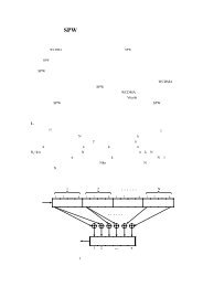
Philips SemiconductorsProduct specification<strong>Fault</strong>-<strong>tolerant</strong> <strong>CAN</strong> <strong>transceiver</strong><strong>TJA1054</strong>handbook, full pagewidthV BATBATTERYP8xC592/P8xCE598<strong>CAN</strong> CONTROLLERV DD+5 V+5 VCTX0 CRXO Px.x Px.x Px.xTXD RXD STB ERR EN INHWAKE273 5 4 6 114BAT<strong>TJA1054</strong><strong>CAN</strong> TRANSCEIVER8 11 12 91013V CCGND100 nFRTH<strong>CAN</strong>H<strong>CAN</strong>LRTL<strong>CAN</strong> BUS LINEMGL425For more information, please refer to the separate FT<strong>CAN</strong> information, available via our websiteFig.7 Application diagram.2001 Nov 20 17
Philips SemiconductorsProduct specification<strong>Fault</strong>-<strong>tolerant</strong> <strong>CAN</strong> <strong>transceiver</strong><strong>TJA1054</strong>BONDING PAD LOCATIONSCOORDINATES (1)SYMBOLPADxyINH 1 206 357TXD 2 211 209RXD 3 850 151ERR 4 1447 151STB 5 2348 143EN 6 2621 280WAKE 7 2621 421RTH 8 2650 1309RTL 9 2459 1880V CC 10 1986 1849<strong>CAN</strong>H 11 972 1880<strong>CAN</strong>L 12 537 1880GND 13a 180 1396GND 13b 180 1281BAT 14 206 812Note1. All coordinates (µm) represent the position of the centre of each pad with respect to the bottom left-hand corner ofthe die (see Fig.8).handbook, full pagewidth121110913a13b82000µm<strong>TJA1054</strong>U14123 4 576x00y2830 µmMGW505Fig.8 Bonding pad locations.2001 Nov 20 18
Philips SemiconductorsProduct specification<strong>Fault</strong>-<strong>tolerant</strong> <strong>CAN</strong> <strong>transceiver</strong><strong>TJA1054</strong>PACKAGE OUTLINESO14: plastic small outline package; 14 leads; body width 3.9 mmSOT108-1DEAXcyH Ev MAZ148pin 1 indexA 2A 1L pQ(A ) 3θA17Leb pw Mdetail X0 2.5 5 mmscaleDIMENSIONS (inch dimensions are derived from the original mm dimensions)UNITmminchesAmax.1.75A 1 A 2 A 3 b p c D (1) E (1) e H (1)E L L p Q v w y Z0.250.100.069 0.0100.0041.451.250.0570.0490.250.010.490.360.0190.0140.250.190.01000.00758.758.550.350.344.03.80.160.151.270.050Note1. Plastic or metal protrusions of 0.15 mm maximum per side are not included.6.25.80.2440.2281.050.0411.00.40.0390.0160.70.60.0280.0240.250.25 0.10.01 0.01 0.004θ0.70.3 o8o0.028 00.012OUTLINEVERSIONREFERENCESIEC JEDEC EIAJEUROPEANPROJECTIONISSUE DATESOT108-1076E06 MS-01297-05-2299-12-272001 Nov 20 19
Philips SemiconductorsProduct specification<strong>Fault</strong>-<strong>tolerant</strong> <strong>CAN</strong> <strong>transceiver</strong><strong>TJA1054</strong>SOLDERINGIntroduction to soldering surface mount packagesThis text gives a very brief insight to a complex technology.A more in-depth account of soldering ICs can be found inour “Data Handbook IC26; Integrated Circuit Packages”(document order number 9398 652 90011).There is no soldering method that is ideal for all surfacemount IC packages. Wave soldering can still be used forcertain surface mount ICs, but it is not suitable for fine pitchSMDs. In these situations reflow soldering isrecommended.Reflow solderingReflow soldering requires solder paste (a suspension offine solder particles, flux and binding agent) to be appliedto the printed-circuit board by screen printing, stencilling orpressure-syringe dispensing before package placement.Several methods exist for reflowing; for example,convection or convection/infrared heating in a conveyortype oven. Throughput times (preheating, soldering andcooling) vary between 100 and 200 seconds dependingon heating method.Typical reflow peak temperatures range from215 to 250 °C. The top-surface temperature of thepackages should preferable be kept below 220 °C forthick/large packages, and below 235 °C for small/thinpackages.Wave solderingConventional single wave soldering is not recommendedfor surface mount devices (SMDs) or printed-circuit boardswith a high component density, as solder bridging andnon-wetting can present major problems.To overcome these problems the double-wave solderingmethod was specifically developed.If wave soldering is used the following conditions must beobserved for optimal results:• Use a double-wave soldering method comprising aturbulent wave with high upward pressure followed by asmooth laminar wave.• For packages with leads on two sides and a pitch (e):– larger than or equal to 1.27 mm, the footprintlongitudinal axis is preferred to be parallel to thetransport direction of the printed-circuit board;– smaller than 1.27 mm, the footprint longitudinal axismust be parallel to the transport direction of theprinted-circuit board.The footprint must incorporate solder thieves at thedownstream end.• For packages with leads on four sides, the footprint mustbe placed at a 45° angle to the transport direction of theprinted-circuit board. The footprint must incorporatesolder thieves downstream and at the side corners.During placement and before soldering, the package mustbe fixed with a droplet of adhesive. The adhesive can beapplied by screen printing, pin transfer or syringedispensing. The package can be soldered after theadhesive is cured.Typical dwell time is 4 seconds at 250 °C.A mildly-activated flux will eliminate the need for removalof corrosive residues in most applications.Manual solderingFix the component by first soldering twodiagonally-opposite end leads. Use a low voltage (24 V orless) soldering iron applied to the flat part of the lead.Contact time must be limited to 10 seconds at up to300 °C.When using a dedicated tool, all other leads can besoldered in one operation within 2 to 5 seconds between270 and 320 °C.2001 Nov 20 20
Philips SemiconductorsProduct specification<strong>Fault</strong>-<strong>tolerant</strong> <strong>CAN</strong> <strong>transceiver</strong><strong>TJA1054</strong>Suitability of surface mount IC packages for wave and reflow soldering methodsSOLDERING METHODPACKAGEWAVE REFLOW (1)BGA, HBGA, LFBGA, SQFP, TFBGA not suitable suitableHBCC, HLQFP, HSQFP, HSOP, HTQFP, HTSSOP, HVQFN, SMS not suitable (2) suitablePLCC (3) , SO, SOJ suitable suitableLQFP, QFP, TQFP not recommended (3)(4) suitableSSOP, TSSOP, VSO not recommended (5) suitableNotes1. All surface mount (SMD) packages are moisture sensitive. Depending upon the moisture content, the maximumtemperature (with respect to time) and body size of the package, there is a risk that internal or external packagecracks may occur due to vaporization of the moisture in them (the so called popcorn effect). For details, refer to theDrypack information in the “Data Handbook IC26; Integrated Circuit Packages; Section: Packing Methods”.2. These packages are not suitable for wave soldering as a solder joint between the printed-circuit board and heatsink(at bottom version) can not be achieved, and as solder may stick to the heatsink (on top version).3. If wave soldering is considered, then the package must be placed at a 45° angle to the solder wave direction.The package footprint must incorporate solder thieves downstream and at the side corners.4. Wave soldering is only suitable for LQFP, TQFP and QFP packages with a pitch (e) equal to or larger than 0.8 mm;it is definitely not suitable for packages with a pitch (e) equal to or smaller than 0.65 mm.5. Wave soldering is only suitable for SSOP and TSSOP packages with a pitch (e) equal to or larger than 0.65 mm; it isdefinitely not suitable for packages with a pitch (e) equal to or smaller than 0.5 mm.2001 Nov 20 21
Philips SemiconductorsProduct specification<strong>Fault</strong>-<strong>tolerant</strong> <strong>CAN</strong> <strong>transceiver</strong><strong>TJA1054</strong>DATA SHEET STATUSDATA SHEET STATUS (1) PRODUCTSTATUS (2)DEFINITIONSObjective data Development This data sheet contains data from the objective specification for productdevelopment. Philips Semiconductors reserves the right to change thespecification in any manner without notice.Preliminary data Qualification This data sheet contains data from the preliminary specification.Supplementary data will be published at a later date. PhilipsSemiconductors reserves the right to change the specification withoutnotice, in order to improve the design and supply the best possibleproduct.Product data Production This data sheet contains data from the product specification. PhilipsSemiconductors reserves the right to make changes at any time in orderto improve the design, manufacturing and supply. Changes will becommunicated according to the Customer Product/Process ChangeNotification (CPCN) procedure SNW-SQ-650A.Notes1. Please consult the most recently issued data sheet before initiating or completing a design.2. The product status of the device(s) described in this data sheet may have changed since this data sheet waspublished. The latest information is available on the Internet at URL http://www.semiconductors.philips.com.DEFINITIONSShort-form specification ⎯ The data in a short-formspecification is extracted from a full data sheet with thesame type number and title. For detailed information seethe relevant data sheet or data handbook.Limiting values definition ⎯ Limiting values given are inaccordance with the Absolute Maximum Rating System(IEC 60134). Stress above one or more of the limitingvalues may cause permanent damage to the device.These are stress ratings only and operation of the deviceat these or at any other conditions above those given in theCharacteristics sections of the specification is not implied.Exposure to limiting values for extended periods mayaffect device reliability.Application information ⎯ Applications that aredescribed herein for any of these products are forillustrative purposes only. Philips Semiconductors makeno representation or warranty that such applications will besuitable for the specified use without further testing ormodification.DISCLAIMERSLife support applications ⎯ These products are notdesigned for use in life support appliances, devices, orsystems where malfunction of these products canreasonably be expected to result in personal injury. PhilipsSemiconductors customers using or selling these productsfor use in such applications do so at their own risk andagree to fully indemnify Philips Semiconductors for anydamages resulting from such application.Right to make changes ⎯ Philips Semiconductorsreserves the right to make changes, without notice, in theproducts, including circuits, standard cells, and/orsoftware, described or contained herein in order toimprove design and/or performance. PhilipsSemiconductors assumes no responsibility or liability forthe use of any of these products, conveys no licence or titleunder any patent, copyright, or mask work right to theseproducts, and makes no representations or warranties thatthese products are free from patent, copyright, or maskwork right infringement, unless otherwise specified.Bare die ⎯ All die are tested and are guaranteed tocomply with all data sheet limits up to the point of wafersawing for a period of ninety (90) days from the date ofPhilips' delivery. If there are data sheet limits notguaranteed, these will be separately indicated in the datasheet. There are no post packing tests performed onindividual die or wafer. Philips Semiconductors has nocontrol of third party procedures in the sawing, handling,packing or assembly of the die. Accordingly, PhilipsSemiconductors assumes no liability for devicefunctionality or performance of the die or systems afterthird party sawing, handling, packing or assembly of thedie. It is the responsibility of the customer to test andqualify their application in which the die is used.2001 Nov 20 22
Philips SemiconductorsProduct specification<strong>Fault</strong>-<strong>tolerant</strong> <strong>CAN</strong> <strong>transceiver</strong><strong>TJA1054</strong>NOTES2001 Nov 20 23
Philips Semiconductors – a worldwide companyContact informationFor additional information please visit http://www.semiconductors.philips.com. Fax: +31 40 27 24825For sales offices addresses send e-mail to: sales.addresses@www.semiconductors.philips.com.© Koninklijke Philips Electronics N.V. 2001 SCA73All rights are reserved. Reproduction in whole or in part is prohibited without the prior written consent of the copyright owner.The information presented in this document does not form part of any quotation or contract, is believed to be accurate and reliable and may be changedwithout notice. No liability will be accepted by the publisher for any consequence of its use. Publication thereof does not convey nor imply any licenseunder patent- or other industrial or intellectual property rights.Printed in The Netherlands 703502/02/pp24 Date of release: 2001 Nov 20 Document order number: 9397 750 08965