TJA1054 Fault-tolerant CAN transceiver
TJA1054 Fault-tolerant CAN transceiver
TJA1054 Fault-tolerant CAN transceiver

Create successful ePaper yourself
Turn your PDF publications into a flip-book with our unique Google optimized e-Paper software.
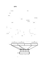
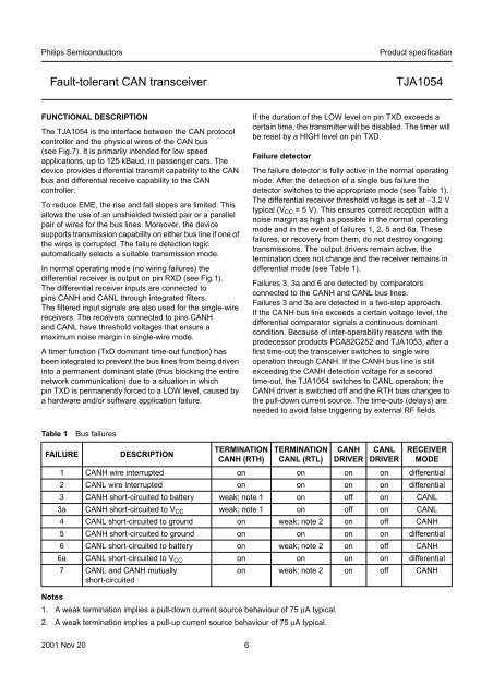
Philips SemiconductorsProduct specification<strong>Fault</strong>-<strong>tolerant</strong> <strong>CAN</strong> <strong>transceiver</strong><strong>TJA1054</strong>FUNCTIONAL DESCRIPTIONThe <strong>TJA1054</strong> is the interface between the <strong>CAN</strong> protocolcontroller and the physical wires of the <strong>CAN</strong> bus(see Fig.7). It is primarily intended for low speedapplications, up to 125 kBaud, in passenger cars. Thedevice provides differential transmit capability to the <strong>CAN</strong>bus and differential receive capability to the <strong>CAN</strong>controller.To reduce EME, the rise and fall slopes are limited. Thisallows the use of an unshielded twisted pair or a parallelpair of wires for the bus lines. Moreover, the devicesupports transmission capability on either bus line if one ofthe wires is corrupted. The failure detection logicautomatically selects a suitable transmission mode.In normal operating mode (no wiring failures) thedifferential receiver is output on pin RXD (see Fig.1).The differential receiver inputs are connected topins <strong>CAN</strong>H and <strong>CAN</strong>L through integrated filters.The filtered input signals are also used for the single-wirereceivers. The receivers connected to pins <strong>CAN</strong>Hand <strong>CAN</strong>L have threshold voltages that ensure amaximum noise margin in single-wire mode.A timer function (TxD dominant time-out function) hasbeen integrated to prevent the bus lines from being driveninto a permanent dominant state (thus blocking the entirenetwork communication) due to a situation in whichpin TXD is permanently forced to a LOW level, caused bya hardware and/or software application failure.If the duration of the LOW level on pin TXD exceeds acertain time, the transmitter will be disabled. The timer willbe reset by a HIGH level on pin TXD.Failure detectorThe failure detector is fully active in the normal operatingmode. After the detection of a single bus failure thedetector switches to the appropriate mode (see Table 1).The differential receiver threshold voltage is set at −3.2 Vtypical (V CC = 5 V). This ensures correct reception with anoise margin as high as possible in the normal operatingmode and in the event of failures 1, 2, 5 and 6a. Thesefailures, or recovery from them, do not destroy ongoingtransmissions. The output drivers remain active, thetermination does not change and the receiver remains indifferential mode (see Table 1).Failures 3, 3a and 6 are detected by comparatorsconnected to the <strong>CAN</strong>H and <strong>CAN</strong>L bus lines.Failures 3 and 3a are detected in a two-step approach.If the <strong>CAN</strong>H bus line exceeds a certain voltage level, thedifferential comparator signals a continuous dominantcondition. Because of inter-operability reasons with thepredecessor products PCA82C252 and TJA1053, after afirst time-out the <strong>transceiver</strong> switches to single wireoperation through <strong>CAN</strong>H. If the <strong>CAN</strong>H bus line is stillexceeding the <strong>CAN</strong>H detection voltage for a secondtime-out, the <strong>TJA1054</strong> switches to <strong>CAN</strong>L operation; the<strong>CAN</strong>H driver is switched off and the RTH bias changes tothe pull-down current source. The time-outs (delays) areneeded to avoid false triggering by external RF fields.Table 1Bus failuresFAILUREDESCRIPTIONTERMINATION<strong>CAN</strong>H (RTH)TERMINATION<strong>CAN</strong>L (RTL)Notes1. A weak termination implies a pull-down current source behaviour of 75 µA typical.2. A weak termination implies a pull-up current source behaviour of 75 µA typical.<strong>CAN</strong>HDRIVER<strong>CAN</strong>LDRIVERRECEIVERMODE1 <strong>CAN</strong>H wire interrupted on on on on differential2 <strong>CAN</strong>L wire interrupted on on on on differential3 <strong>CAN</strong>H short-circuited to battery weak; note 1 on off on <strong>CAN</strong>L3a <strong>CAN</strong>H short-circuited to V CC weak; note 1 on off on <strong>CAN</strong>L4 <strong>CAN</strong>L short-circuited to ground on weak; note 2 on off <strong>CAN</strong>H5 <strong>CAN</strong>H short-circuited to ground on on on on differential6 <strong>CAN</strong>L short-circuited to battery on weak; note 2 on off <strong>CAN</strong>H6a <strong>CAN</strong>L short-circuited to V CC on on on on differential7 <strong>CAN</strong>L and <strong>CAN</strong>H mutuallyshort-circuitedon weak; note 2 on off <strong>CAN</strong>H2001 Nov 20 6