TJA1054 Fault-tolerant CAN transceiver
TJA1054 Fault-tolerant CAN transceiver
TJA1054 Fault-tolerant CAN transceiver

You also want an ePaper? Increase the reach of your titles
YUMPU automatically turns print PDFs into web optimized ePapers that Google loves.
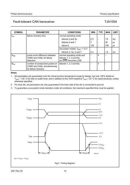
Philips SemiconductorsProduct specification<strong>Fault</strong>-<strong>tolerant</strong> <strong>CAN</strong> <strong>transceiver</strong><strong>TJA1054</strong>t rec failure recovery time normal operating modefailures 3 and 3a 0.3 − 1.6 msfailures 4 and 7 7 − 38 µsfailure 6 125 − 750 µslow power modes; V BAT =12Vfailures 3, 3a, 4 and 7 0.3 − 1.6 msN detN recSYMBOL PARAMETER CONDITIONS MIN. TYP. MAX. UNITpulse-count difference between<strong>CAN</strong>H and <strong>CAN</strong>L for failuredetectionnumber of consecutive pulses on<strong>CAN</strong>H and <strong>CAN</strong>L simultaneouslyfor failure recoverynormal operating mode andfailures 1, 2, 5 and 6a;pin ERR becomes LOW− 4 −failures 1, 2, 5 and 6a − 4 −Notes1. All parameters are guaranteed over the virtual junction temperature range by design, but only 100% tested atT amb = 125 °C for dies on wafer level, and in addition to this 100% tested at T amb =25°C for cased products, unlessotherwise specified.2. For bare die, all parameters are only guaranteed if the back side of the die is connected to ground.3. To guarantee a successful mode transition under all conditions, the maximum specified time must be applied.handbook, full pagewidthV TXDV CC0 VV <strong>CAN</strong>LV <strong>CAN</strong>H5 V3.6 V1.4 V0 V2.2 VV diff−3.2 V−5 VV RXDt PD(L) t PD(H)0.7V CC0.3V CCMGL424V diff =V <strong>CAN</strong>H − V <strong>CAN</strong>L .Fig.4 Timing diagram.2001 Nov 20 15