TJA1054 Fault-tolerant CAN transceiver
TJA1054 Fault-tolerant CAN transceiver
TJA1054 Fault-tolerant CAN transceiver

Create successful ePaper yourself
Turn your PDF publications into a flip-book with our unique Google optimized e-Paper software.
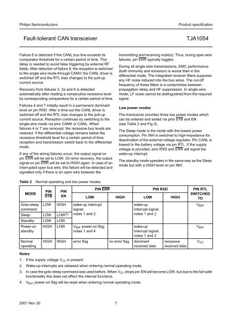
Philips SemiconductorsProduct specification<strong>Fault</strong>-<strong>tolerant</strong> <strong>CAN</strong> <strong>transceiver</strong><strong>TJA1054</strong>Failure 6 is detected if the <strong>CAN</strong>L bus line exceeds itscomparator threshold for a certain period of time. Thisdelay is needed to avoid false triggering by external RFfields. After detection of failure 6, the reception is switchedto the single wire mode through <strong>CAN</strong>H; the <strong>CAN</strong>L driver isswitched off and the RTL bias changes to the pull-upcurrent source.Recovery from failures 3, 3a and 6 is detectedautomatically after reading a consecutive recessive levelby corresponding comparators for a certain period of time.Failures 4 and 7 initially result in a permanent dominantlevel on pin RXD. After a time-out the <strong>CAN</strong>L driver isswitched off and the RTL bias changes to the pull-upcurrent source. Reception continues by switching to thesingle-wire mode via pins <strong>CAN</strong>H or <strong>CAN</strong>L. Whenfailures 4 or 7 are removed, the recessive bus levels arerestored. If the differential voltage remains below therecessive threshold level for a certain period of time,reception and transmission switch back to the differentialmode.If any of the wiring failures occur, the output signal onpin ERR will be set to LOW. On error recovery, the outputsignal on pin ERR will be set to HIGH again. In case of aninterrupted open bus wire, this failure will be detected andsignalled only if there is an open wire between thetransmitting and receiving node(s). Thus, during open wirefailures, pin ERR typically toggles.During all single-wire transmissions, EMC performance(both immunity and emission) is worse than in thedifferential mode. The integrated receiver filters suppressany HF noise induced into the bus wires. The cut-offfrequency of these filters is a compromise betweenpropagation delay and HF suppression. In single-wiremode, LF noise cannot be distinguished from the requiredsignal.Low power modesThe <strong>transceiver</strong> provides three low power modes whichcan be entered and exited via pins STB and EN(see Table 2 and Fig.3).The Sleep mode is the mode with the lowest powerconsumption. Pin INH is switched to high-impedance fordeactivation of the external voltage regulator. Pin <strong>CAN</strong>L isbiased to the battery voltage via pin RTL. If the supplyvoltage is provided, pins RXD and ERR will signal thewake-up interrupt.The standby mode operates in the same way as the Sleepmode but with a HIGH level on pin INH.Table 2Normal operating and low power modesMODEGoto-sleepcommandPINSTBPINENLOW HIGH wake-up interruptsignal;notes 1 and 2Sleep LOW LOW (3)Standby LOW LOWPower-onstandbyNormaloperatingHIGH LOW V BAT power-on flag;notes 1 and 4PIN ERR PIN RXD PIN RTLSWITCHEDLOW HIGH LOW HIGH TOwake-upinterrupt signal;notes 1 and 2wake-upinterrupt signal;notes 1 and 2HIGH HIGH error flag no error flag dominantreceived datarecessivereceived dataNotes1. If the supply voltage V CC is present.2. Wake-up interrupts are released when entering normal operating mode.3. In case the goto-sleep command was used before. When V CC drops pin EN will become LOW, but due to the fail-safefunctionality this does not effect the internal functions.4. V BAT power-on flag will be reset when entering normal operating mode.V BATV BATV CC2001 Nov 20 7