1.8 METER SERIES 1194 ANTENNA SYSTEM - General Dynamics ...
1.8 METER SERIES 1194 ANTENNA SYSTEM - General Dynamics ...
1.8 METER SERIES 1194 ANTENNA SYSTEM - General Dynamics ...

Create successful ePaper yourself
Turn your PDF publications into a flip-book with our unique Google optimized e-Paper software.
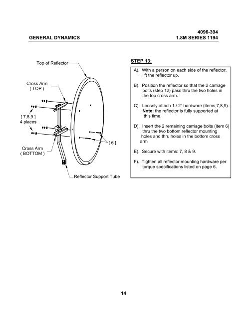
4096-394GENERAL DYNAMICS <strong>1.8</strong>M <strong>SERIES</strong> <strong>1194</strong>Top of ReflectorCross Arm( TOP )[ 7,8,9 ]4 placesCross Arm( BOTTOM )[ 6 ]Reflector Support TubeSTEP 13:A). With a person on each side of the reflector,lift the reflector up.B). Position the reflector so that the 2 carriagebolts (step 12) pass thru the two holes inthe top cross arm.C). Loosely attach 1 / 2” hardware (items,7,8,9).Note: the reflector is fully supported atthis time.D). Insert the 2 remaining carriage bolts (item 6)thru the two bottom reflector mountingholes and thru holes in the bottom crossarmE). Secure with items: 7, 8 & 9.F). Tighten all reflector mounting hardware pertorque specifications listed on page 6.14