Summer/Winter Switch - Modine
Summer/Winter Switch - Modine
Summer/Winter Switch - Modine

You also want an ePaper? Increase the reach of your titles
YUMPU automatically turns print PDFs into web optimized ePapers that Google loves.
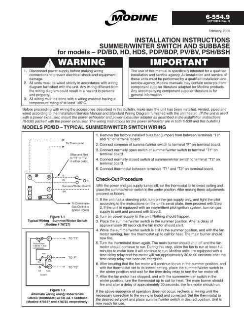
6-554.95H71985A Rev. HFebruary, 2005INSTALLATION INSTRUCTIONSSUMMER/WINTER SWITCH AND SUBBASEfor models – PD/BD, HD, HDS, PDP/BDP, PV/BV, PSH/BSHWARNING1. Disconnect power supply before making wiringconnections to prevent electrical shock and equipmentdamage.2. All units must be wired strictly in accordance with wiringdiagram furnished with the unit. Any wiring different fromthe wiring diagram could result in a hazard to personsand property.3. All wiring must be done with a wiring material having atemperature rating of at least 105°C.Before proceeding with wiring the accessories described in this bulletin, make sure the unit has been installed, vented, piped andwired according to the Installation/Service Manual and Standard Wiring Diagram furnished with the unit heater. (If the unit is usedwith a power exhauster, mount the power exhauster and power exhauster adapter as described in the installation instructions(6-530) packed with the power exhauster. The wiring instructions for the power exhauster are in both 6-530 and this bulletin.)MODELS PD/BD – TYPICAL SUMMER/WINTER SWITCH WIRINGIMPORTANTThe use of this manual is specifically intended for a qualifiedinstallation and service agency. All installation and service ofthese units must be performed by a qualified installation andservice agency. <strong>Modine</strong> manuals may contain excerpts fromcomponent supplier literature adapted for <strong>Modine</strong> products.Any accompanying component supplier literature is forgeneral information.T1CVT2FGRBLBKTo Thermostat(Blue and Redto “T1” or “T2”in either order)<strong>Summer</strong>/<strong>Winter</strong> <strong>Switch</strong>To CombinationGas Control orIgnition ControlFigure 1.1Typical Wiring – <strong>Summer</strong>/<strong>Winter</strong> <strong>Switch</strong>(<strong>Modine</strong> # 78727)RobertshawCM260 T-Statw/SubbaseOnOffFanSystemRGAutoWAutoTO “T1”TO “F”TO “T2”Figure 1.2Alternate wiring using RobertshawCM260 Thermostat w/ SB-3A-1 Subbase(<strong>Modine</strong> #79187 and #78785 respectively)➞➞➞1. Remove the factory installed buss bar (jumper) from between terminals "T2"and "F" of terminal board.2. Connect common of summer/winter switch to terminal "F" on terminal board.3. Connect normally open switch of summer/winter switch to terminal "T1" onterminal board.4. Connect normally closed switch of summer/winter switch to terminal "T2" onterminal board.5. Connect thermostat between terminals "T1" and "T2" on terminal board.Check-Out ProcedureWith the power and gas supply turned off, set the thermostat to its lowest setting andplace the summer/winter switch to the winter position. After making these adjustmentsproceed as follows.1. If the unit has a standing pilot, turn on the gas supply only, and light the pilotaccording to the instructions on the unit’s serial plate, then proceed with Step2. If the unit is equipped with an intermittent pilot ignition system, turn on gassupply to unit and proceed with Step 2.2. Turn on power supply to the unit. Nothing should happen.3. Place the summer/winter switch in the summer position. After a delay ofapproximately 30 seconds the fan motor should start.4. While the summer/winter switch is still in the summer position, and with the fanmotor running, turn the thermostat up to call for heat. The main burner shouldnow fire.5. Turn the thermostat down again. The main burner should shut off and the fanmotor should continue to run. During this step, allow the fan to run at least 1 1 /2minutes to make sure it will continue to run. <strong>Modine</strong> units are equipped with atime delay relay and the motor will run approximately 30 to 90 seconds after thetime delay relay has been de-energized.6. After insuring that the fan motor will continue to run in the summer position, andwith the thermostat set to its lowest setting, place the summer/winter switch inthe winter position and wait for the time delay relay to turn the fan motor off.7. After the fan motor has stopped, and with the summer/winter switch in thewinter position, turn the thermostat up to call for heat. The main burner shouldfire and after a delay of approximately 30 seconds, the fan motor should run.If the above sequence of operation does not occur, recheck all wiring until thenecessary correction to the wiring is found and corrected. Set the thermostat tothe desired set point and place summer/winter switch in desired position. Unit isnow ready for use.
MODELS PD/BD – COMBINATION SUMMER/WINTER SWITCH AND POWER EXHAUSTERTerminal Boardon Junction BoxRTo L1To L2CST1CVRFGTo Thermostat(Blue and Redto “T1” or “T2”in either order)Figure 2.1Typical Wiring – Combination PowerExhauster <strong>Switch</strong> with<strong>Summer</strong>/<strong>Winter</strong> <strong>Switch</strong>(<strong>Modine</strong> #78727)RobertshawCM260 T-Statw/SubbaseOnOffFanSystemRGAutoWAutoT2BL1 324RBL<strong>Summer</strong>/<strong>Winter</strong> <strong>Switch</strong>BKBLTo CombinationGas Control orIgnition ControlPowerExhausterMotorTO “T1”TO “F”TO “T2”Figure 2.2Alternate wiring, using RobertshawCM260 thermostat w/ SB-3A-Subbase(<strong>Modine</strong> # 79187 and #78785 respectively)➞➞➞1. Remove the factory installed bus bars (jumpers) between terminals "T2" and "F",and between terminals "C" and "V".2. Connect common of summer/winter switch to terminal "F" of terminal board.3. Connect normally open switch of summer/winter switch to terminal "T1" ofterminal board.4. Connect normally closed switch of summer/winter switch to terminal "T2" ofterminal board.5. Connect one red lead from centrifugal switch (CS) of power exhauster to terminal"C" of terminal board and connect the other red lead from centrifugal switch (CS)to terminal "V" of terminal board.6. Connect terminal (3) of power exhauster relay to terminal "T2" of terminal board.7. Connect terminal (1) of power exhauster relay to terminal "G" of terminal board.8. Connect terminal (2) of power exhauster relay to L1 of power supply in unitjunction box.9. Connect L2 lead from power exhauster motor to L2 lead of power supply in unitjunction box.10. Connect thermostat between terminals "T1" and "T2" of terminal board.Check-Out ProcedureWith the power and gas supply turned off, set the thermostat to its lowest settingand place the summer/winter switch in the winter position. After making theseadjustments, proceed as follows.1. If the unit has a standing pilot, turn on the gas supply only, and light the pilotaccording to the instructions on the unit’s serial plate, then proceed with Step 2.If the unit is equipped with an intermittent pilot ignition system, turn on gas supplyto the unit and proceed with Step 2.2. Turn on power supply to the unit. Nothing should happen.3. Place the summer/winter switch in the summer position. After a delay of 30 to 90seconds only the fan motor should start.4. While the summer/winter switch is still in the summer position, and with the fanmotor running, turn the thermostat up to call for heat. The power exhauster motorshould come on, the centrifugal switch should close, and the main burnershould fire.5. Turn the thermostat down again. The main burner and power exhauster motorshould shut off, but the fan motor should continue to run. During this step, allowthe fan to run at least 90 seconds to make sure it will continue running. <strong>Modine</strong>units are equipped with a time delay relay and the motor will run 30 to 90 secondsafter the time delay relay has been de-energized.6. After insuring that the fan will continue to run in the summer position, and with thethermostat set at its lowest setting, place the summer/winter switch in the winterposition and wait for the time delay relay to turn the fan motor off.7. After the fan motor has stopped, and with the summer/winter switch in the winterposition, turn the thermostat up to call for heat. The power exhauster should start,the centrifugal switch should close and the main burner should fire. After a delayof 30 to 90 seconds fan motor should run.8. Turn the thermostat down again. The main burner and power exhauster motorshould shut off. The fan motor should continue to run for 30 to 90 seconds andthen shut off.9. Check the power exhauster centrifugal switch for proper function. To do this,remove the centrifugal switch lead from terminal "V" of the terminal board. Turnup the thermostat to call for heat. The power exhauster motor should run, butthe main burner should not light. After a 30 second delay, the fan motor shouldoperate. The main burner should still not fire.10. Turn down the thermostat and allow the power exhauster motor and fan motor tostop running. Reconnect the centrifugal switch lead to terminal "V" of the terminalboard. Recycle the unit as described in Steps 7 and 8.If the unit does not operate in the sequence describe above, recheck all of thewiring until the necessary correction to the wiring is found and corrected. Set thethermostat to the desired set point and switch the summer/winter switch to thedesired position. The unit is now ready for use.2
MODELS HD, HDS - TYPICAL SUMMER/WINTER (OR SUBBASE) SWITCH WIRINGRobertshawCM260 T-Statw/SubbaseOnFanRGAutoWOff AutoSystemTO “R”TO “G”TO “W”HD Series 103, HDS Series 101 Alternatewiring using Robertshaw CM260Thermostat w/ SB-3A-1 Subbase (<strong>Modine</strong>#79187 and #78785 respectively)RobertshawCM260 T-Statw/SubbaseOnFanRGAutoWOff AutoSystem<strong>Summer</strong>/<strong>Winter</strong>Function:Remove W-Gjumper bart˚R W GSWFigure 3.1Series 103 Typical Wiring - <strong>Summer</strong>/<strong>Winter</strong> <strong>Switch</strong> (<strong>Modine</strong> #7827)(24v Thermostat, 115v or 200/230v<strong>Summer</strong>/<strong>Winter</strong> <strong>Switch</strong>)Figure 3.3HD Series 101 & 102 Wiring usingRobertshaw CM260 Thermostat w/ SB-3A-1 Subbase (<strong>Modine</strong> #79187 and #78785respectively)➞➞➞Figure 3.2➞➞➞TO “R”TO “H”TO “W”Installation procedures that follow are for units with the corresponding series identitynumber that may be found in the 5th through the 7th digits of the serial number. Forexample, a unit with the serial number "30011033603-0981" has the 5th through the7th digits as 103 as shown underlined above. Match the series ID from the unit serialplate with the series ID listed in the heading of the following directions to determinewhich Procedure corresponds to your unit.Installation Procedure (HD Series 103, HDS Series 101)1. Turn off gas and power supply to the unit.2. Remove the factory installed jumper bar between "W" and "G" terminals on thecircuit board.3. Connect the common of the summer/winter switch to the "G" terminalof the circuit board.4. Connect the normally open terminal of the summer/winter switch to the"R" terminal of the circuit board.5. Connect the normally closed terminal of the summer/winter switch tothe "W" terminal of the circuit board.6. Connect the thermostat between the "R" and the "W" terminal on thecircuit board.Installation Procedure (HD Series 101 & 102)1. Turn of gas and power supply to the unit.2. Remove the blue jumper wire between the "W" terminal on the circuitboard and the "H" terminal of the time delay relay.3. Connect the "G" terminal of the sub base to the "H" terminal of theTime Delay Relay.4. Connect the "R" terminal of the sub base to the "R" terminal of thecircuit board.5. Connect the "W" terminal of the sub base to the "W" terminal of thecircuit board.Check-Out ProcedureWith the gas and power supply turned off, set the thermostat to its lowest setting andplace the summer/winter switch (or thermostat fan control) in the "winter" (or "auto")position. After making these adjustments proceed as follows.1. Turn on the gas supply.2. Turn on the power supply to the unit. Nothing should happen.3. Place the summer/winter switch (or thermostat fan control) in the "summer" (or"on") position. After a delay of approximately 60 (30-110 for series 101 & 102)seconds the fan motor should start.4. While the summer/winter switch (or thermostat fan control) is still in the “summer"(or "on") position, and with the fan motor running, turn the thermostat up to callfor heat. The power exhauster should start and after approximately 30 secondsthe burner should fire.5. Turn the thermostat down again. The burner should shut off and the fan motorshould continue to run. During this step, allow the fan to run at least 1 ½ minutesto make sure it will continue to run. Hot Dawg units are equipped with a timedelay feature that allows the fan to run for 50 (45 for series 101 & 102) secondsto cool the heat exchanger after a call for heat.6. After insuring that the fan motor will continue to run in the "summer" (or "on")position, set the thermostat to its lowest setting. Place the summer/winter switch(or thermostat fan control) in the "winter" (or "auto") position and wait for the timedelay to turn the fan motor off.7. After the fan motor has stopped, and with the summer/winter switch (orthermostat fan control) in the "winter" (or "auto") position, turn the thermostat upto call for heat. The power exhauster should start, the burner should light inapproximately 30 seconds and after a delay of approximately 60 seconds, thefan should start.If the above sequence of operation does not occur, recheck all wiring until thenecessary corrections to the wiring is found and corrected. Set the thermostat tothe desired set point and place the summer/winter switch (or thermostat fancontrol) in the desired position. Unit is now ready for use.3
MODELS PDP/BDP/PV/BV – TYPICAL SUMMER/WINTER SWITCH WIRINGTerminalBoardOn J-BoxT1T2To ThermostatBlueorRed2 4TD RelayTerminals In UnitJ-BoxBKTerminalBoardOn J-BoxT1T2To thermostat<strong>Summer</strong>/<strong>Winter</strong> <strong>Switch</strong>Relay By Others(24v Relay Coil,Line Volt Contacts)CFCFVG<strong>Summer</strong>/<strong>Winter</strong> <strong>Switch</strong>To CombinationGas Control orIgnition ControlFigure 4.1Typical Wiring – <strong>Summer</strong>/<strong>Winter</strong> <strong>Switch</strong> (<strong>Modine</strong> # 78727)(24v Thermostat, 115v or 200/230v <strong>Summer</strong>/<strong>Winter</strong> <strong>Switch</strong>)VGTo CombinationGas Control orIgnition Control2 4RelayTD Relay TerminalsIn J-BoxFigure 4.2Typical Wiring – <strong>Summer</strong>/<strong>Winter</strong> <strong>Switch</strong> (<strong>Modine</strong> # 78727)(24v Thermostat, 24v <strong>Summer</strong>/<strong>Winter</strong> <strong>Switch</strong>)RobertshawCM260 T-Statw/ SubbaseT1CVOnFanAutoOff AutoSystemTerminalBoardOn J-BoxRGWT2FGRelay By Others(24v Relay Coil,Line Volt Contact)Wire to HotLead of PowerExhausterMotorTD RelayTerminalIn J-BoxTo CombinationGas Control orIgnition ControlFigure 4.3Alternate Wiring Using Robertshaw CM260Thermostat w/SB-3A-1 Subbase(25v Thermostat and Subbase)(<strong>Modine</strong> #79187 and #78785 respectively)3Relay1. Turn off gas and power supply to unit.2. Determine which method of summer/winter control is desired, Figure 4.1, 4.2 or 4.3.3. Wire unit according to the method selected. Note: If the method selected is asdescribed in Figure 4.3, the factory supplied buss bar between terminals "T2"and "F" must be removed prior to wiring in thermostat and subbase.4. Check wiring using the Check-Out Procedure.Check-Out ProcedureWith the power and gas supply turned off, set the thermostat to its lowest setting andplace the summer/winter switch to the winter position. After making these adjustmentsproceed as follows:1. Turn on gas and power supply to the unit. Nothing should happen.2. Place the summer/winter switch in the summer position. The fan motor should start,except when wired as shown in Figure 4.3. In that case, after a delay of30 to 90 seconds, the fan motor should start.3. While the summer/winter switch is still in the summer position, and with the fan motorrunning, turn the thermostat up to call for heat. The power exhauster motor shouldcome on, the pressure switch should close, and the main burner should fire. Allowburner to fire for 1 to 2 minutes.4. Turn the thermostat down again. The main burner should shut off and the fan motorshould continue to run. During this step, allow the fan to run at least 90 seconds tomake sure it will continue running. <strong>Modine</strong> units are equipped with a time delay relayand the motor will run 30 to 90 seconds after the time delay relay has been deenergized.5. After insuring that the fan motor will continue to run in the summer position, and withthe thermostat set to its lowest setting, place the summer/winter switch in the winterposition and wait for the time delay relay to turn the fan motor off.6. After the fan motor has stopped, and with the summer/winter switch in the winterposition, turn the thermostat up to call for heat. The power exhauster motor shouldcome on, the pressure switch should close, the main burner should fire and after adelay of 30 to 90 seconds, the fan motor should run.If the above sequence of operation does not occur, recheck all wiring until thenecessary correction to the wiring is found and corrected. Set the thermostat to thedesired set point and place summer/winter switch in desired position. Unit is now readyfor use.4
MODELS PSH/BSH – TYPICAL SUMMER/WINTER SWITCH WIRINGTerminalBoardOn J-BoxT1T2To ThermostatBlueorRed1 3TD-2 RelayTerminals in J-BoxBKTerminalBoardOn J-BoxT1T2To Thermostat<strong>Summer</strong>/<strong>Winter</strong> <strong>Switch</strong>Relay By Others(24v Relay Coil,Line Volt Contacts)CFCFVGTo Ignition Control<strong>Summer</strong>/<strong>Winter</strong> <strong>Switch</strong>Figure 5.1Typical Wiring – <strong>Summer</strong>/<strong>Winter</strong> <strong>Switch</strong> (<strong>Modine</strong> # 78727)(24v Thermostat, 115v or 200/230v <strong>Summer</strong>/<strong>Winter</strong> <strong>Switch</strong>)T1CVRobertshawCM260 T-Statw/SubbaseOnFanAutoRGWOff AutoSystemT2FGTD1 RelayTerminalsin J-BoxTD2 RelayTerminalin J-BoxTo IgnitionControlFigure 5.3Alternate Wiring Using Robertshaw CM260Thermostat w/SB-3A-1 Subbase(25v Thermostat and Subbase)(<strong>Modine</strong> #79187 and #787851. Turn off gas and power supply to unit.2. Determine which method of summer/winter control is desired,Figure 5.1, 5.2 or 5.3.3. Wire unit according to the method selected. Note: If themethod selected is as described in Figure 5.3, the factorysupplied buss bar between terminals "T2" and "F" mustbe removed prior to wiring in thermostat and subbase.a. Remove TD1 relay yellow wire from unit "F" terminaland connect to unit "T2" terminal.b. Remove TD2 relay brown wire from (4) terminal onTD1 and wire to unit "F" terminal.c. Wire thermostat "R" terminal to unit "T1" terminal.d. Wire thermostat "G" terminal to unit "F" terminal.e. Wire thermostat "W" terminal to unit "T2" terminal.4. Check wiring using the Check-Out Procedure.HTD1H1 32 4HTD2H1 3To Hot Leadof PowerExhaust MotorTo IgnitionControlTo Hot Leadof Fan MotorVGTo IgnitionControl1 3RelayTD-2 Relay Terminalsin J-BoxFigure 5.2Typical Wiring – <strong>Summer</strong>/<strong>Winter</strong> <strong>Switch</strong> (<strong>Modine</strong> # 78727)(24v Thermostat, 24v <strong>Summer</strong>/<strong>Winter</strong> <strong>Switch</strong>)Check-Out ProcedureWith the power and gas supply turned off, set the thermostatto its lowest setting and place the summer/winter switch to thewinter position. After making these adjustments proceed asfollows:1. Turn on gas and power supply to the unit.Nothing should happen.2. Place the summer/winter switch in the summer position.The fan motor should start, except when wired as shownin Figure 5.3. In that case, after a delay of approximately30 seconds, the fan motor should start.3. While the summer/winter switch is still in the summerposition, and with the fan motor running, turn thethermostat up to call for heat. The power exhauster motorshould come on, the pressure switch should close andthe main burner should fire. Allow burner to fire for1 to 2 minutes.4. Turn the thermostat down again. The main burner shouldshut off and the fan motor should continue to run. Duringthis step, allow the fan to run at least 90 seconds to makesure it will continue running. <strong>Modine</strong> units are equippedwith a time delay relay and the motor will run approximately30 to 90 seconds after the time delay relayhas been de-energized.5. After insuring that the fan motor will continue to run in thesummer position, and with the thermostat set to its lowestsetting, place the summer/winter switch in the winterposition and wait for the time delay relay to turn the fanmotor off.6. After the fan motor has stopped, and with the summer/winterswitch in the winter position, turn the thermostat up to callfor heat. The power exhauster motor should come on, thepressure switch should close, the main burner should fireand after a delay of approximately 30 seconds, the fan motorshould run.If the above sequence of operation does not occur, recheck allwiring until the necessary correction to the wiring is found andcorrected. Set the thermostat to the desired set point and placesummer/winter switch in desired position. Unit is now readyfor use.5
INFORMATION INSTRUCTIONS — LOW VOLTAGE RELAYElectrical DataCoil — 24V 50/60 HzContact — Rated at 1 hp @ 125V, 2 hp @ 250VRelay contains one pair of normally open (NO) contacts forload switching.Physical DataDimensions — 3" H x 2- 5 /8" W x 2- 1 /2" L (See Figure 5.1)Enclosure — General Purpose with 1/2" conduit connectorApplicationLow voltage relays can be used for controlling multiple units offof one thermostat, isolation of power exhauster motors whensummer fan switches are used, or as unit interlocks betweenthe unit and other mechanical equipment.Figure 6.3Mounting of Low Voltage RelayTo FanMotorTo PowerExhauster Motor(TOP VIEW)Knockout forPower toUnit HeaterInstallation<strong>Modine</strong> low voltage relays are shipped separately for fieldmounting and wiring.When this low voltage relay is to be used to isolate the powerexhauster on PV/BV/PSH/BSH models during the summer, orwhen a summer/winter switch or thermostat sub-base is used,it may be desirable to mount the relay directly to the unit heaterjunction box. This can be accomplished with the use of a 1 /2",Rigid to Box Pulling Elbow and mounting the relay as shown.(See Figure 6.2)FieldMountedRelayUnit HeaterJ-Box with TerminalBoard90° Connector(1/2" Rigid to BoxPulling Elbow)Top of Heater(SIDE VIEW)Figure 6.1Low Voltage RelayRear of UnitHeaterFigure 6.3Illustration of <strong>Summer</strong>/<strong>Winter</strong> Toggle <strong>Switch</strong>BUBUComponents of Kit 3H604839A(<strong>Summer</strong>/<strong>Winter</strong> switch wiringshown on pages 1, 2, 3 and 4)RelayRelay Coil Leads<strong>Switch</strong> Assembly Exploded ViewHRLRRRWRelay Contact LeadsThis switch is rated at 15 amps. 125 volts;and 10 amps. at 250 volts.6
CHVAC&R Division • <strong>Modine</strong> Manufacturing Company • 1500 DeKoven Avenue • Racine, Wisconsin 53403-2552Phone: 1-800-828-4328 (HEAT) • www.modine.com© <strong>Modine</strong> Manufacturing Company 2005 2/05 - Litho in USA