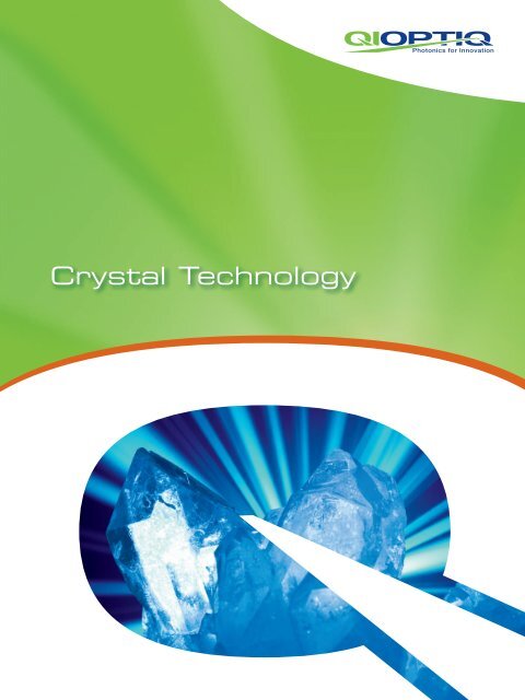
Crystal Technology - Qioptiq Q-Shop
Crystal Technology - Qioptiq Q-Shop
Crystal Technology - Qioptiq Q-Shop
- No tags were found...

Create successful ePaper yourself
Turn your PDF publications into a flip-book with our unique Google optimized e-Paper software.
<strong>Crystal</strong> <strong>Technology</strong>1
202Company Profile<strong>Qioptiq</strong> designs and manufactures photonic productsand solutions, serving a wide range of markets andapplications in the medical and life sciences, industrialmanufacturing, defense and aerospace, and researchand development sectors.The company is known for its high-quality standardcomponents, products and instruments, custommodules and assemblies, leading-edge innovation,precision manufacturing and responsive globalsourcing. Due to a series of acquisitions, <strong>Qioptiq</strong>has an impressive history and pedigree, benefitingfrom the knowledge and experience of LINOS,Point Source, Rodenstock Precision Optics, Spindler& Hoyer, Gsänger, Optem, Pilkington, Avimo andothers. With a total workforce exceeding 2,300,<strong>Qioptiq</strong> has a worldwide presence with locationsthroughout Europe, Asia and the USA.187718981966196919841991RodenstockfoundedSpindler & HoyerfoundedPilkington PELtd. founded,which laterbecomesTHALES OpticsGsängerOptoelektronikfoundedOptemInternationalfoundedPoint Sourcefounded
Medical &Life SciencesIndustrialManufacturingIndexDefense &AerospaceCompany Profile 02 – 03Core Competencies 04 – 05LINOS Faraday Isolators – Introduction 06 – 09Single Stage Faraday Isolators 10 – 17Isolators with a Broad Tuning Rage 18 – 20Two Stage Faraday Isolators 21 – 24Questionnaire Faraday Isolators 2503Research &DevelopmentLINOS Pockels Cells andLaser Modulators – Introduction 26LINOS Pockels Cells – Technical Information 27 – 31LINOS Pockels Cells 32 – 43Questionnaire Pockels Cells 44LINOS Laser Modulators –Technical Information 45 – 46Amplifiers 47 – 48LINOS Laser Modulators 48 – 53Questionnaire Laser Modulators 5419962000200120052006 / 20072010LINOS foundedthrough the mergerof Spindler & Hoyer,Steeg & ReuterPräzisionsoptik,Franke Optik andGsänger OptoelektronikRodenstockPräzisionsoptikacquiredby LINOSAVIMO Groupacquiredby THALES<strong>Qioptiq</strong>founded asTHALES sellsHigh TechOptics Group<strong>Qioptiq</strong> acquiresLINOS and Point Sourceas “members of the<strong>Qioptiq</strong> group”The new <strong>Qioptiq</strong>consolidates allgroup membersunder one brand
404Core Competencies<strong>Qioptiq</strong> offers the most comprehensive set oftechnologies and knowledge to fulfill the demandsof almost any modern application in the field ofphotonics.Our decades of interdisciplinary experience in manymarkets enable us to provide a portfolio of design,technologies and manufacturing capabilities suitablefor your specific application. We can supply asolution that will boost your competitive edge andsupport your efforts to optimize your products. Ourcomponents, modules and systems have superiorspecifications – such as optimum optical resolution,highest transmission, superior beam quality andmuch more.Design and development• Optical system design includingnon-linear optics• Mechanical design• Characterization of crystals• FEM-analysis including magneticand thermal effects• Standard and Sol-Gel coatingtechnologies• Numerous product patents• Lasers for biotechnology andmetrology
05Materials• Non-linear crystals: KD*P, BBO, RTP,ADP, LiNbO 3, TGG and others• Various optical materials for UV to IRapplications• Metals, magnets and various polymermaterialsAssembly technologies• Development of in-house processesfor assembly of electro- andmagneto-optical systems• Glueing technologies• Flow-box assembly
LINOS Faraday IsolatorsOverviewApertureSingle StageFI-600/1100-8SIFI-1060-8SIFI-390/420-5SVFI-420/460-5SVFI-500/820-5SVFI-600/1100-5SIFI-500/780-5SV5 mmFI-405-5SV FI-488-5SVBroadbandFI-x-5SVFI-x-5SIFI-x-5SV BB07MicrobenchFI-x-5SV MBLow PowerFI-x-5LPCompactFI-488-5SCFI-x-5SC3.5 mmCompactFI-488-3SCFI-x-3SC2 mmWavelengthFI-x-2SV400 500FI-x-2SI600 700 800 900 1000 1100 1200ApertureTwo Stage5 mmWavelengthAperture4 mmWavelengthLPE-<strong>Technology</strong>
LINOS Faraday IsolatorsTGG <strong>Crystal</strong>NMaximum TransmissionS08CharacteristicsPolarizerFaraday RotatorPrinciple of OperationFaraday isolators are optical components whichallow light travel in only one direction. Their mode ofoperation is based on the non-linear Faraday effect direction of the magnetic field (±45°) and the(magneto rotation). In principle, the function of an exit polarizer is also oriented at ±45°, so that theoptical isolator is analogue to that of an electrical maximum beam intensity is transmitted.diode.If light of any polarization, but with a reversed directionFaraday isolators are composed of three elements: of propagation, meets the exit polarizer, it leaves• Entrance Polarizerat ±45°, passes through the Faraday rotator and is• Faraday Rotatoragain rotated by ±45°. The non-reciprocal nature of• Exit Polarizerthe Faraday effect results in the direction of rotationonce again being counter clockwise as viewed in theThin film polarizers are commonly used as entrance north/south direction of the magnetic field. Uponand exit polarizers, typically in form of a special leaving the Faraday rotator, the polarization haspolarizing beam splitter cube. These polarizers have gone through two ±45° rotations resulting in a totalan extremely high extinction ratio and are designed rotation of ±90°. In this polarization direction thefor use with high power lasers. The polarizer entrance light is deflected laterally by the entrance polarizer.and exit surfaces are coated with an antireflectivecoating for the specified wavelength range. The key Increased Isolationelement of the Faraday isolator is the Faraday rotator. The maximum isolation of the Faraday isolator isThe rotator consists of a strong permanent magnet limited by inhomogenities of the TGG crystal andcontaining a crystal with a high Verdet constant. the magnetic field. However, it is possible to squarethe extinction ratio by placing two isolators in seriesLight of any polarization entering the entrance and by arranging the polarity of the two magnets topolarizer exits as horizontally or vertically linearly be opposite to each other. This way the polarizationpolarized light. Since laser light is usually linearly direction of the transmitted light remains unchangedpolarized, one can match the orientation of the in the transmission direction and the effect of bothentrance polarizer and the laser by simply rotating magnetic fields is enhanced. This arrangement alsothe isolator. Light then passes through the Faraday leads to a more compact isolator. The strength ofrotator. For most wavelengths the crystal is a Terbium this effect depends on the distance between theGallium Garnet (TGG) crystal which is placed in a two magnets and can be used to tune the isolator tostrong homogeneous magnetic field. <strong>Crystal</strong> length different wavelengths. The adjustment is necessaryand magnetic field strength are adjusted so that because the rotational angle of the TGG crystal isthe light polarization is rotated by 45° on exiting wavelength and temperature dependent. Please seethe crystal. In the figure above the light is rotated chapter “Two stage isolators” (page 21) for morecounter clockwise when viewed in the north/south information.NMaximum Extinction
LINOS Faraday IsolatorsAdvantagesHigh IsolationThe properties of the LINOS Faraday isolator aredetermined by the quality of the optical elements andthe uniformity of the magnetic field. The entrance andexit polarizers exhibit a very high extinction ratio, sothat the isolation is mainly limited by inhomogenitiesin the crystal material. Specially selected crystalmaterials with a high Verdet constant combined withpermanent magnets with a high remanence enableus to use shorter crystals and obtain an isolation> 30 dB.The radiation blocked by the entrance and exitpolarizers is not absorbed internally, but is deflectedby 90° with respect to the beam direction. Thisensures a stable thermal operation even at higherlaser power levels. The blocked radiation can be usedfor other applications. All optical surfaces are slightlytilted relative to the beam axis.Low Insertion LossThe high transmission, typically > 90%, is achievedby using absorption free materials and antireflectivecoatings with low residual reflectivity on all entranceand exit surfaces.Three sides of the entrance and exit polarizers areusable and readily accessible for easy cleaning. Thedegree of isolation can be adjusted in a wide range.Mounting FlexibilityThe LINOS Faraday isolators can be mounted directlyvia threaded holes in the housing or via additionalbase plates or angle brackets.ApplicationsThe ongoing development and refinement oflaser technology have created a need for opticalcomponents that shield the laser resonator fromback reflections. LINOS Faraday isolators providean efficient method of suppressing instabilities andintensity fluctuations in laser devices.Typical applications are:• Protection of the resonator in solid state and gaslasers from back reflections• Prevention of parasitic oscillation in multistage solidstate amplifiers• Protection of diode lasers against back scatter andextraneous light09Large Aperture, Compact DesignAll optical elements have been aligned to eliminatebeam shading and allow for easy adjustment.Focusing is not necessary.The compact design is achieved by using rare earthmagnets with the highest remanent magnetism andTGG crystal material with a high Verdet constant. Theisolator is suitable for divergent beams or in setupswith limited space. A minimal optical path length inthe isolator results in the lowest possible influenceon the image.large aperturecompact designhigh isolationlow insertionloss
LINOS Faraday IsolatorsSingle Stage Faraday Isolators10Technical OverviewThe compact LINOS Faraday isolators in this chapteruse a single stage rotator. The length is kept to aminimum with the use of powerful permanentmagnets in an optimized geometry. A 360° rotationof the exit polarizer provides a maximum extinctionover a certain range around the central wavelength.The entrance and exit polarizers are polarizing beamsplitter cubes. The blocked radiation is diverted by90° and is readily available for other applications. At30 dB, the specification of the isolator is sufficientfor most standard applications. For specializedapplications, selected isolators with an extinction upto 45 dB are available.An even higher extinction is provided by the twostage isolator series.Wavelength tuningThe Verdet constant of the TGG crystal is dependentupon wavelength and temperature. In order tocompensate for different temperatures or differentwavelengths, it is possible to tune the isolator inorder to achieve maximum extinction. Tuning theisolator is accomplished by rotating the holder of theexit polarizer with respect to an engraved angularscale.Broadband optionOn Broadband (BB) models the isolation is improvedover a broadband spectrum by compensatingrotational dispersion of the TGG. This renders thedevice usable over a wavelength range of ±50 nmwithout additional adjustment. The isolators can bemounted on rods, cylindrical mounts or by using theassembly surfaces so that the laser polarization canbe oriented horizontally or vertically.ApplicationsThe following single stage LINOS Faraday isolatorsare suitable for all lasers operating in the rangeespecially:• Ar+ and Kr+ lasers• other Ion lasers• HeNe lasers• other gas lasers• Dye lasers• Diode lasers• Ti:Sapphire lasers• Cr:LiCAF lasers• Short pulse lasers• Mode-synchronized lasers• Alexandrite lasersThe graph shows the typical reduction factor of thetransmission (Δλ) that is due to the tuning of theisolator to a wavelength λ that is different from thedesign wavelength λ 0. The bar has a length that coversthe wavelength range for which 0.95 < T(Δλ) < 1.The bullet indicates the design wavelength λ 0. Theoverall transmission of a Faraday isolator is equal toT t= T 0x T(Δλ), where T 0is a factor that representsthe transmission of the polarizers. At the designwavelength the overall transmission of the Faradayisolator is T 0> 90%Reduction of transmission T(Δλ) [%]Tuning of design wavelength Δλ
LINOS Faraday IsolatorsIsolators with 2mm Aperture,SV / SI-SeriesFI-x-2SV / FI-x-2SIFI-x-2SV (x = 530, 630, 680 nm)• Isolation better than 30 dB / typically38 - 42 dB over the entire wavelengthrange, custom isolation values on request• TGG crystal• Rare earth magnet• Output polarizer, 360° rotation, engravedtuning scale• Access to blocked beam• Mounting 2SV-version: via two M3threaded holes at the bottom side,20 mm separation• Damage threshold > 200 mJ / cm 2 forpulses of 10 ns (1064 nm)• Damage threshold > 28 mJ / cm 2 forpulses of 280 fs (850 nm, 20 Hz)11FI-x-2SI (x = 760, 820, 990, 1060 nm)FI-x-2SV / FI-x-2SIProductIsolation,guaranteed /typical(dB)Transmissionat designwavelength(%)Transmissionat boundrywavelength(%)Tuningrangetypical(nm)Aperture(mm)Dimen sionsIsolator(mm)Order-NoFI-530-2SV > 30/38-42 > 90 > 85 505 - 565 Ø 2 25x25x37 84 50 1010 007FI-630-2SV > 30/38-42 > 90 > 85 595 - 670 Ø 2 25x25x37 84 50 1011 000FI-680-2SV > 30/38-42 > 90 > 85 645 - 725 Ø 2 25x25x37 84 50 1010 009FI-760-2SI > 30/38-42 > 90 > 85 720 - 810 Ø 2 Ø 40x91 84 50 1034 007FI-820-2SI > 30/38-42 > 90 > 85 775 - 875 Ø 2 Ø 40x91 84 50 1034 008FI-990-2SI > 30/38-42 > 90 > 85 940 - 1050 Ø 2 Ø 40x91 84 50 1034 009FI-1060-2SI > 30/38-42 > 90 > 85 1010 - 1120 Ø 2 Ø 40x91 84 50 1034 010Subject to technical changes
LINOS Faraday IsolatorsIsolators with 3.5 and 5mmAperture, SC-SeriesFI-x-3SC / FI-x-5SC12FI-x-3SC (x = 488, 980, 1064, 1120 nm)FI-x-5SC (x = 488, 930, 1064, 1120 nm)• Extreme compact design• Isolation better than 30 dB, typically38-42 dB over the entire wavelengthrange, custom isolation values on request• TGG crystal• Rare earth magnet• Output polarizer, 360° rotation, engravedtuning scale• Access to blocked beam• Optional version with Brewster platepolarizers (BP) on request for FI-1060-xSC,isolation better than 30 dB• Mounting:via four M2 threaded holes at the bottomside and at backside; 15 x 22.5 mmseparation (3SC-version, exceptFI-1210-3SC);49.5 x 22.5 mm separation(FI-1210-3SC);13 x 22.5 mm separation (5SC-version)• Damage threshold > 200 mJ / cm 2 forpulses of 10 ns (1064 nm)• Damage threshold > 28 mJ / cm 2 forpulses of 280 fs (850 nm, 20 Hz)FI-1210-3SC, -5SCFI-x-3SC / FI-x-5SCProductIsolation,guaranteed/typical(dB)Transmissionat designwavelength(%)Transmissionat boundrywavelength(%)Tuningrangetypical(nm)A p er tu re( m m )Dim ensi ons(mm )Order-NoFI-488-3SC* > 35/38-42 > 90 - 478 - 498 Ø 3.5 40x40x60 84 51 1090 0016FI-488-5SC* > 35/38-42 > 90 - 478 - 498 Ø 5 45x45x58 84 51 1090 0013FI-980-3SC > 30/38-42 > 90 > 85 925 - 1040 Ø 3.5 40x40 x60 84 50 1036 004FI-930-5SC > 30/38-42 > 90 > 85 880 - 990 Ø 5 45x45 x58 84 50 1037 007FI-1060-3SC > 30/38-42 > 90 > 85 1010 - 1120 Ø 3.5 40x40 x60 84 50 1036 001FI-1060-5SC > 30/38-42 > 90 > 85 1010 - 1120 Ø 5 45x45 x58 84 50 1037 001FI-1120-3SC > 30/38-42 > 90 > 85 1080 - 1170 Ø 3.5 40x40x60 84 51 1010 0057FI-1120-5SC > 30/38-42 > 90 > 85 1080 - 1170 Ø 5 45x45x58 84 51 1010 0009FI-1210-3SC > 30/38-42 > 90 > 85 1160 - 1260 Ø 3.5 45x45 x96 84 51 1010 0043FI-1210-5SC > 30/38-42 > 90 > 85 1160 - 1260 Ø 5 45x45 x96 84 51 1010 0053*optical contacted polarizersSubject to technical changes
LINOS Faraday IsolatorsIsolators with 5mm Aperture,LP-SeriesFI-x-5LP• Faraday Isolator, low power• Isolation better than 38 dB• TGG crystal• Rare earth magnet• In- and output polarizer rotatableFI-x-5LP (x = 630, 680, 780, 850 nm)• Mounting:via two M4 threaded holes at the bottomside, 30 mm separation• Damage threshold > 25 W / cm 213FI-x-5LPProductIsolation,guaranteed(dB)Transmission atdesign wavelength(%)Tuning rangetypical(nm)Aper ture(mm)DimensionIsolator(mm)Order-NoFI-630-5LP > 38 > 70 595 - 670 Ø 5 41x40x40 84 51 1010 0098FI-680-5LP > 35 > 75 645 - 725 Ø 5 41x40x40 84 51 1010 0100FI-780-5LP > 38 > 85 750 - 810 Ø 5 41x40x40 84 51 1010 0091FI-850-5LP > 38 > 85 810 - 905 Ø 5 41x40x40 84 51 1010 0099Subject to technical changes
LINOS Faraday IsolatorsIsolators with 5mm Aperture,SV / SI-SeriesFI-x-5SV / FI-x-5SI• Isolation better than 30 dB, typically38-42 dB over the entire wavelengthrange, custom isolation values on request• TGG crystal• Rare earth magnet• Output polarizer, 360° rotation, engravedtuning scale• Access to blocked beam14FI-x-5SV (x = 530, 630, 730, 780, 810, 850 nm)FI-x-5SI (x = 488, 910, 960, 1000, 1060 nm)• Optional version with Brewster platepolarizers (BP) on request for FI-1060-5SI,isolation better than 30 dB• For upgrading to broadband-version referto chapter Special Isolators• Mounting:via two M4 threaded holes at the bottomside and at the back side;30 mm separation (5SV-version); 40 mmseparation (5SI-version); or via base plate• Base plate included• Damage threshold > 200 mJ / cm 2 forpulses of 10 ns (1064 nm)• Damage threshold > 28 mJ / cm 2 forpulses of 280 fs (850 nm, 20 Hz)FI-x-5SV / FI-x-5SIItem TitleIsolationguaranteed /typical(dB)Transmissionat designwavelength(%)Transmissionat boundrywavelength(%)Tuningrangetypical(nm)Aperture(mm)Dimens ionsIsolator(mm)Dimensionsbase plate(LxWxH)(mm)Order-NoFI-405-5SV* > 35 > 88 - 400 - 420 Ø5 40x56x90 - 84 51 1010 0131FI-488-5SI* > 30/38-42 > 90 > 85 478 - 498 Ø5 58x58x95 70x58x8 84 50 1030 000FI-530-5SV > 30/38-42 > 90 > 85 505 - 565 Ø5 40x40x55 50x30x9.5 84 50 1013 002FI-630-5SV > 30/38-42 > 90 > 85 595 - 670 Ø5 40x40x55 50x30x9.5 84 50 1013 004FI-730-5SV > 30/38-42 > 90 > 85 690 - 780 Ø5 40x40x55 50x30x9.5 84 50 1013 034FI-780-5SV > 30/38-42 > 90 > 85 740 - 830 Ø5 40x40x55 50x30x9.5 84 50 1013 008FI-810-5SV > 30/38-42 > 90 > 85 765 - 865 Ø5 40x40x55 50x30x9.5 84 50 1013 033FI-850-5SV > 30/38-42 > 90 > 85 805 - 905 Ø5 40x40x55 50x30x9.5 84 50 1013 027FI-910-5SI > 30/38-42 > 90 > 85 860 - 970 Ø5 58x58x95 70x58x8 84 50 1031 002FI-960-5SI > 30/38-42 > 90 > 85 910 - 1020 Ø5 58x58x95 70x58x8 84 50 1031 006FI-1000-5SI > 30/38-42 > 90 > 85 950 - 1060 Ø5 58x58x95 70x58x8 84 50 1031 014FI-1060-5SI > 30/38-42 > 90 > 85 1010 - 1120 Ø5 58x58x95 70x58x8 84 50 1031 000*optical contacted polarizersSubject to technical changes
LINOS Faraday IsolatorsIsolators with 8mm Aperture,SI-SeriesFI-1060-8SIFI-1060-8SI• Isolation better than 30 dB, typically38-42 dB over the entire wavelengthrange, custom isolation values on request• TGG crystal• Rare earth magnet• Output polarizer, 360° rotation, engravedtuning scale• Access to blocked beam• Optional version with Brewster platepolarizers (BP) on request, isolation betterthan 30 dB• Mounting:via two M4 threaded holes at the bottomside and at the back side;55 mm separation, or via base plate• Base plate included• Damage threshold > 200 mJ / cm 2 forpulses of 10 ns (1064 nm)• Damage threshold > 28 mJ / cm 2 forpulses of 280 fs (850 nm, 20 Hz)15FI-1060-8SIItemTitleIsolation,guaranteed /typical(dB)Transmissionat designwavelength(%)Transmissionat boundarywavelength(%)Tuningrangetypical(nm)Aperture(mm)Dimen sionsIsolato r(mm)Dimensionsbase plate(LxWxH)(mm)Order-NoFI-1060-8SI > 30/38-42 > 90 > 80 1010-1120 Ø 8 76x76x95 85x76x8 84 50 1032 000Subject to technical changes
LINOS Faraday IsolatorsSpecial Isolators with 5mmAperture, SV-SeriesFI-x-5SV-MB / FI-x-5SV-BBFI-x-5SV-MB (x = 530, 630, 730, 780, 810, 850 nm)• Isolation better than 30 dB, typically38-42 dB over the entire wavelengthrange, custom isolation values on request• TGG crystal• Rare earth magnet• Output polarizer, 360° rotation, engravedtuning scale• Access to blocked beam16FI-x-5SV-BB (x = 780, 820 nm)• MB-version: compatible to theMicrobench system• BB-version: for multiline lasers orspectrally broadband lasers such asfs-laser systems• Mounting BB-version:via two M4 threaded holes at the bottomside and at the back side;30 mm separation, or via base plate• Base plate included• Damage threshold > 200 mJ / cm 2 forpulses of 10 ns (1064 nm)• Damage threshold > 28 mJ / cm 2 forpulses of 280 fs (850 nm, 20 Hz)FI-x-5SV-MB / FI-x-5SV-BBProductIsolationguaranteed/t ypical(dB)Transmissionat designwavelength(%)Transmissionat boundarywavelength(%)Tuningrangetypical(nm)Aperture(mm)Dimens ionsIsolator(mm)Dimensionsbase plate(LxWxH)(mm)Order-NoFI-530-5SV-MB > 30/38-42 > 90 > 85 505 - 565 Ø 5 42x36x65 - 84 50 1014 002FI-630-5SV-MB > 30/38-42 > 90 > 85 595 - 670 Ø 5 42x36x65 - 84 50 1014 004FI-730-5SV-MB > 30/38-42 > 90 > 85 690 - 780 Ø 5 42x36x65 - 84 50 1014 034FI-780-5SV-MB > 30/38-42 > 90 > 85 740 - 830 Ø 5 42x36x65 - 84 50 1014 008FI-810-5SV-MB > 30/38-42 > 90 > 85 765 - 865 Ø 5 42x36x65 - 84 50 1014 033FI-850-5SV-MB > 30/38-42 > 90 > 85 805 - 905 Ø 5 42x36x65 - 84 50 1014 001FI-780-5SV-BB > 30/38-42 > 90 > 85 725 - 825 Ø 5 40x40x61 50x30x9.5 84 50 1024 008FI-820-5SV-BB > 30/38-42 > 90 > 85 760 - 860 Ø 5 40x40x61 50x30x9.5 84 50 1024 009Subject to technical changes
LINOS Faraday Isolators4mm Aperture Isolators withMagnetooptical <strong>Crystal</strong> FilmFI-x-4SLFI-x-4SL (x = 1310, 1550 nm)• Extremely small size• Isolation better than 35 dB• Faraday material: magneto-optical crystalfilm in saturation• Rare earth magnet• Output polarizer, 360° rotation• Access to blocked beam• Max. cw power: 2 W• Damage threshold > 100 MW / cm 2 forpulses of 20 ns (1550 nm)17FI-x-4SLItem TitleIsolation,guaranteed/typical(dB)Transmissionat designwavelength(%)Transmisionat boundarywavelength(%)Tuning rangetypical(nm)Aperture(mm)DimensionsIsolator(mm)Order-NoFI-1250-4SL > 35 > 85 > 80 1200 - 1300 Ø 4 14x23.5 84 51 102 000 04FI-1310-4SL > 35 > 90 > 85 1260 - 1360 Ø 4 14x23.5 84 50 1071 000FI-1550-4SL > 35 > 90 > 85 1485 - 1615 Ø 4 14x23.5 84 50 1072 000Subject to technical changes
LINOS Faraday IsolatorsIsolators with a BroadTuning Range18Technical OverviewIntroductionThe function of the tunable LINOS Faraday isolatorsin the following chapter is based on a single stageisolator. Precision mechanics allow a continuousadjustment of the interaction between the magneticfield and the TGG crystal without moving any opticalcomponents.It is possible to set the rotation angle to any valuebetween 0° to 45° within the wavelength rangein order to study the effects of varying degreesof feedback. Easy access to the blocked beam isprovided by polarizing beam splitter cubes, whichdivert the blocked beam by 90°.Precision mechanics allow the exact reproductionof adjustments previously established. And with theaddition of an optional micrometer display, an angularresolution in the arc minute range is achievable. Theincorporation of very powerful magnets ensures acompact and efficient design.OperationThe isolator can be mounted on rods, cylindricalmounts or by using the assembly surfaces so thatthe laser polarization can be oriented horizontally orvertically. The entry and exit polarizers can be easilycleaned by removing the security rings.• Ar+ and Kr+ lasers• other Ion lasers• HeNe lasers• Other gas lasers• Diode lasers• Nd:YAG lasers• Ti: Sapphire lasers• Cr:LiCAF lasers• Dye lasers• Alexandrite lasers• Mode-locked lasers• Short Pulse lasersApplicationsThese isolators are suitable for all lasers operatingin the 390-420 nm respectively in the 500-1100 nmwavelength range especially for:Faraday RotatorFor every laser line selected from 390 nm to amaximum of 1100 nm, every polarization directionfrom 0° to 90° is precise and reproducible.
LINOS Faraday Isolators5mm Aperture Tunable Isolators,SV / SI-SeriesFI-x/y-5SV / FI-600/1100-5SI• Continuous adjustment for wavelengthwithout movement of optical partsFI-x/y-5SV• Tunable with maximum transmission andisolation over the complete wavelengthrange• Isolation better than 30 dB, typically38 - 42 dB over the entire wavelengthrange, custom isolation values on request• TGG crystal• Rare earth magnet• Access to blocked beam19FI-600/1100-5SI• Mounting:via two M4 threaded holes at the bottomside and at the back side;20 mm separation (5SV-version);55 mm separation (5SI-version);or via base plate, or via angle bracket(5SV-version only)• Base plate included• Angle bracket included (5SV-version only)• Damage threshold > 200 mJ / cm 2 forpulses of 10 ns (1064 nm)• Damage threshold > 28 mJ / cm 2 forpulses of 280 fs (850 nm, 20 Hz)FI-x/y-5SV, FI-x/y-5SIProductIsolation,guaranteed /typical(dB)Transmissionat designwavelength(%)Tuning rangetypical(nm)Aperture(mm)Dimen sionsIsolator(mm)Dimensionsbase plate(LxWxH)(mm)Order-NoFI-390/420-5SV > 30/38-42 > 90 390-420 Ø 5 60x60x77 54x60x8 84 50 1046 000FI-420/460-5SV > 30/38-42 > 90 420-460 Ø 5 60x60x77 54x60x8 84 50 1046 001FI-500/820-5SV > 30/38-42 > 90 500-820 Ø 5 60x60x77 54x60x8 84 50 1041 000FI-600/1100-5SI > 30/38-42 > 90 600-1100 Ø 5 80x80x125 88x90x8 84 50 1044 000Subject to technical changesHigh qualityA precise mechanics enables a continuous wavelength adjustment.Without movement of the optics a broad wavelength range isrealized.
LINOS Faraday Isolators8mm Aperture Tunable Isolator,SI-SeriesFI-600/1100-8SI20FI-600/1100-8SI• Continuous adjustment for wavelengthwithout movement of optical parts• Tunable with maximum transmission andisolation over the complete wavelength• Isolation better than 30 dB, typically38-42 dB over the entire wavelengthrange, custom isolation values on request• TGG crystal• Rare earth magnet• Access to blocked beam• Mounting:via two M4 threaded holes at the bottomside and at the back side;55 mm separation, or via base plate• Base plate included• Damage threshold > 200 mJ / cm 2 forpulses of 10 ns (1064 nm)• Damage threshold > 28 mJ / cm 2 forpulses of 280 fs (850 nm, 20 Hz)FI-600/1100-8SIItem TitleIsolation,guaranteed/typical(dB)Trans missio n(%)Tuning rangetypical(nm)Ape rtur e(mm )DimensionsIsolator(mm)Dimensionsbase plate(LxWxH)(mm)Order-NoF I- 6 0 0 / 1 1 0 0 -8 S I > 30/38-42 > 90 600 - 1100 Ø 8 80x80x125 88x90x8 84 50 1045 000Subject to technical changesA closer lookThe excellent quality of the high-precision LINOS electro-optics from<strong>Qioptiq</strong> is a testament to decades of experience at both Gsänger and<strong>Qioptiq</strong>. The 40-year history of these products is marked by immensecustomer satisfaction, and has established <strong>Qioptiq</strong> as a leader in lasertechnology.Dr. Gsänger, founder of Gsänger Optics in Munich, was instrumental in the success ofthe electro-optics.
Two Stage FaradayIsolatorsTechnical OverviewFI-x-5TI and FI-x-5TVDiode lasers are extremely sensitive to reflectedradiation. Standard Faraday isolators typically achievebetween 30 dB and 40 dB isolation, which in somecases is not sufficient to suppress undesirablefeedback.Our two stage LINOS Faraday isolators weredeveloped for the special requirements of diodelasers and square the standard isolation of single stageFaraday isolators. At the heart of this developmentis the use of two coupled isolator stages togetherwith the best polarizers available on the market.This configuration combines the exit polarizer ofthe first stage with the entry polarizer of the secondstage to form one central polarizer.Arranging the polarity of the two magnets to beopposite to each other results in two benefits:The polarization direction of the transmitted lightremains unchanged in the transmission directionand the effect of both magnetic fields is enhanced.Therefore this configuration also leads to a morecompact isolator and a reduction of the optical pathlength which in turn enhances the optical quality ofthe LINOS Faraday isolator.All optical surfaces are antireflection coated andthe surfaces normal to the beam axis are tilted.The polarizers are mounted in a way that allowseasy cleaning of the external optical surfaces. Thisguarantees that the isolation is not reduced byresidual reflections and scattering from the isolator.Based on this specialdesign a guaranteed60 dB isolation at thedesign wavelength, respectively within theadjustment range of ±10 nm, makes Linos two stageFaraday isolators the best on the market.DLI, OverviewThe isolators of the DLI-series were developed forthe special requirements of diode lasers in the visiblespectrum and combine the outstanding isolation ofa two stage isolator with the flexibility of a tunableisolator.The DLI isolators are easily integrated into an existingsetup and can be adjusted to match any wavelengthwithout changing the laser polarization or displacingthe laser beam. The isolators can be coarsely tunedby altering the effective magnetic field in the twoisolator stages. A precise wavelength adjustmentis possible by rotating the central polarizer witha micrometer set screw. The blocked radiation isdeflected out of the isolator at 90° with respect tothe beam axis. It is not absorbed by the interior ofthe isolator, but is available at the side surfaces of thepolarizer and the exit window.DLI Injection LockingThe DLI injection version revolves this operating modeand uses the exit window for in-coupling of the seedlaser for injection locking while decoupling efficientlythe master and the slave laser from each other atthe same time. Like this stable mode locking (e.g. ofTi:Sapphire lasers) is simplified.21
LINOS Faraday IsolatorsApplicationsAll two stage LINOS Faraday isolators are typicallyused to improve the power and frequency stability ofdiode lasers used in spectroscopy, interferometry andprecision control as well as in alignment applications.Since the output polarization and the beam positionare conserved for all two stage LINOS Faradayisolators, the influence of the smallest feedbackeffects on the laser can be quantitatively examined.22
LINOS Faraday Isolators5mm Aperture Two Stage FaradayIsolators (non-tunable), TV / TI-SerieFI-x-TV / FI-x-TIFI-x-TVFI-x-TI• Two coupled isolator stages in series• Especially high isolation > 60 dB• TGG crystal• Rare earth magnet• TV-version: wavelength range ±10 nmdepending on the central wavelength• TI-version: wavelength adjustable• Customized central wavelength onrequest• Mounting TV-version:via two M4 threaded holes at the bottomside, 30 mm separation• Mounting TI-version:via two M4 threaded holes at the bottomside or at the back side,40 mm separation, or via base plate• Base plate includedHigh qualityHigh isolation (60 dB) and hightransmission for wavelengthsfrom 650 nm to 1060 nm isguaranteed.23• Damage threshold > 200 mJ / cm 2 forpulses of 10 ns (1064 nm)• Damage threshold > 28 mJ / cm 2 forpulses of 280 fs (850 nm, 20 Hz)FI-x-TV / FI-x-TIProductIsolation,guaranteed(dB)Transmissionat designwavelength (%)Tuning rangetypical(nm)A p er tu re( m m )DimensionsIsolator(mm)Dimensionsbase plate(LxWxH)(mm)Order-NoFI-650-TV ≥ 60 ≥ 80 - Ø 5 40x40x106 - 84 51 1010 0044FI-670-TV ≥ 60 ≥ 80 - Ø 5 40x40x106 - 84 50 1060 020FI-710-TV ≥ 60 ≥ 80 - Ø 5 40x40x106 - 84 50 1060 019FI-760-TV ≥ 60 ≥ 80 - Ø 5 40x40x106 - 84 50 1060 017FI-780-TV ≥ 60 ≥ 80 - Ø 5 40x40x106 - 84 50 1060 002FI-810-TV ≥ 60 ≥ 80 - Ø 5 40x40x106 - 84 50 1060 003FI-850-TV ≥ 60 ≥ 80 - Ø 5 40x40x106 - 84 50 1060 009FI-920-TI ≥ 60 ≥ 80 885-960 Ø 5 58x58x131 70x58x8 84 50 1061 001FI-950-TI ≥ 60 ≥ 80 915-990 Ø 5 58x58x131 70x58x8 84 50 1061 002FI-980-TI ≥ 60 ≥ 80 940-1020 Ø 5 58x58x131 70x58x8 84 50 1061 003FI-1060-TI ≥ 60 ≥ 80 1000-1080 Ø 5 58x58x131 70x58x8 84 50 1061 004Other wavelengths available upon requestSubject to technical changes
LINOS Faraday Isolators5mm Aperture Two Stage FaradayIsolators (tunable), DLI-SeriesTunable Diode Laser Isolators DLI24• Tunable with maximum isolation overthe complete wavelength range• Two coupled isolator stages in series• Especially high Isolation > 60 dB• TGG crystal• Rare earth magnet• Input polarization = outputpolarization• Individually calibrated adjustmentcurve supplied with each isolator• Mounting:via four M4 threaded holes at the bottomside and at the back side;40 x 40 mm separation, or via base plate• Base plate included• Special version for injection locking onrequest• Damage threshold > 200 mJ / cm 2 forpulses of 10 ns (1064 nm)• Damage threshold > 28 mJ / cm 2 forpulses of 280 fs (850 nm, 20 Hz)DLI-xProductIsolation,guaranteed(dB)Transmission at designwavelength(%)Tuning rangetypical(nm)A pe rt ur e(m m)DimensionsIsolator(mm)Dimensions baseplate (LxWxH)(mm)Order-NoDLI 1 ≥ 60 ≥ 80 754-890 Ø5 50x50x97 50x60x10 84 50 1003 000DLI 2 ≥ 60 ≥ 80 610-700 Ø5 50x50x97 50x60x10 84 50 1002 000DLI 3 ≥ 60 ≥ 80 650-760 Ø5 50x50x97 50x60x10 84 50 1001 000Subject to technical changesA closer lookAn easy integration of DLI isolators is possible. They can be adjustedeasily without changing laser polarization or beam position. Specialversions for injection locking on request.
LINOS Faraday IsolatorsFaraday Isolators - QuestionnaireQIOPTIQ Photonics GmbH & Co. KG<strong>Crystal</strong> <strong>Technology</strong>Hans-Riedl-Straße 985622 FeldkirchenGermanyPhone +49(0)89 255 458-100Fax +49(0)89 255 458-895E-mail laser@qioptiq.deInternet www.qioptiq.com• Full Name: _____________________________________________• Company Name: ________________________________________• Address: _______________________________________________• Zip Code: ______________________________________________• Country: _______________________________________________• Phone: ________________________________________________• Fax: ___________________________________________________• City: __________________________________________________251. Laser Parameters at Location of Faraday Isolator1.1 Wavelength [nm] ____________________________________________________________________________________________________1.2 Type of Laser _______________________________________________________________________________________________________1.3 Beam Diameter, 1/e 2 [mm] _____________________________________________________________________________________________1.4 CW / Pulsed ________________________________________________________________________________________________________1.5 Laser Pulse Energy [mJ] _______________________________________________________________________________________________1.6 Laser Pulse Duration [ps] ______________________________________________________________________________________________1.7 Repetition Rate [Hz] __________________________________________________________________________________________________2. Type of Faraday Isolator2.1 Hard Aperture [mm] __________________________________________________________________________________________________2.2 Transmission [%] ____________________________________________________________________________________________________2.3 Extinction 1) [dB] _____________________________________________________________________________________________________1)Single stage: > 30dB, typically 38 - 42dB. Two stage: > 60dB, custom isolation values on request3. Miscellaneous3.1 Temperature @ operation ____________________________________________________________________________________________33.2 Year [No. of Units] Target Price / Unit ____________________________________________________________________________________4. Comments / Remarks:__________________________________________________________________________________________________________________________________________________________________________________________________________________________________________________________________________________________________________________________________________________________________
LINOS Pockels Cells & Laser ModulatorsThe LINOS Pockels Cellsand Laser Modulators26Electro-optical modulators are divided intomodulators (for applications outside of laser cavity)and Pockels cells (for applications within laser cavity)on the following pages.You can choose from a large selection of crystals fora variety of applications, apertures and laser outputs,covering the entire wavelength range from 250 nmto 3 μm. The consistently high <strong>Qioptiq</strong> quality andincomparable value of our products is assured bya combination of our many years of experience,an intelligent design, modern engineering withcomputer simulations and sophisticated processing.In addition we offer a broad range of fast and highperformancehigh-voltage drivers. For details, pleasecontact our staff from the customer service.!Special features:On request we can customize products forwavelengths in the 250 nm to 3 μm range.Ideal areas of application:Phase and intensity modulation; Q-switching; pulsepicking.<strong>Qioptiq</strong> quality criteria:Best possible extinction ratio for each crystalHigh transmissionPatented isolation system minimizespiezoelectric oscillation for exceptionallyprecise switching operations (optional)More information:Contact us to receive the complete <strong>Qioptiq</strong> offer inour LINOS catalog by mail, or look for it under:www.qioptiq-shop.com
LINOS Pockels Cells & Laser ModulatorsPockels Cells,Technical InformationThe Electro-Optic EffectThe linear electro-optic effect, also known as thePockels effect, describes the variation of the refractiveindex of an optical medium under the influence of anexternal electrical field. In this case certain crystalsbecome birefringent in the direction of the opticalaxis which is isotropic without an applied voltage.When linearly polarized light propagates along thedirection of the optical axis of the crystal, its stateof polarization remains unchanged as long as novoltage is applied. When a voltage is applied, thelight exits the crystal in a state of polarization whichis in general elliptical.This way phase plates can be realized in analogyto conventional polarization optics. Phase platesintroduce a phase shift between the ordinary andthe extraordinary beam. Unlike conventional optics,the magnitude of the phase shift can be adjustedwith an externally applied voltage and a λ/4 or λ/2retardation can be achieved at a given wavelength.This presupposes that the plane of polarization ofthe incident light bisects the right angle betweenthe axes which have been electrically induced. In thelongitudinal Pockels effect the direction of the lightbeam is parallel to the direction of the electric field.In the transverse Pockels cell they are perpendicularto each other. The most common application of thePockels cell is the switching of the quality factor of alaser cavity.Q-SwitchingLaser activity begins when the threshold conditionis met: the optical amplification for one round tripin the laser resonator is greater than the losses(output coupling, diffraction, absorption, scattering).The laser continues emitting until either the storedenergy is exhausted, or the input from the pumpsource stops. Only a fraction of the storage capacityis effectively used in the operating mode. If it werepossible to block the laser action long enough tostore a maximum energy, then this energy could bereleased in a very short time period.A method to accomplish this is called Q-switching.The resonator quality, which represents a measureof the losses in the resonator, is kept low until themaximum energy is stored. A rapid increase of theresonator quality then takes the laser high abovethreshold, and the stored energy can be releasedin a very short time. The resonator quality can becontrolled as a function of time in a number ofways. In particular, deep modulation of the resonatorquality is possible with components that influencethe state of polarization of the light. Rotating thepolarization plane of linearly polarized light by 90°,the light can be guided out of the laser by a polarizer.The modulation depth, apart from the homogeneityof the 90° rotation, is only determined by the degreeof extinction of the polarizer. The linear electrooptical(Pockels) effect plays a predominant rolebesides the linear magneto-optical (Faraday) and thequadratic electro-optical (Kerr) effect. Typical electroopticQ-switches operate in a so called λ/4 mode.27
LINOS Pockels Cells28a) Off Q-SwitchingLight emitted by the laser rod (1) is linearly polarizedby the polarizer (2). If a λ/4 voltage is applied to thePockels cell (3), then on exit, the light is circularlypolarized. After reflection from the resonator mirror(4) and a further passage through the Pockels cell,the light is once again polarized, but the plane ofpolarization has been rotated by 90°. The light isdeflected out of the resonator at the polarizer, but theresonator quality is low and the laser does not startto oscillate. At the moment the maximum storagecapacity of the active medium has been reached,the voltage of the Pockels cell is turned off veryrapidly; the resonator quality increases immediatelyand a very short laser pulse is emitted. The use of apolarizer can be omitted for active materials whichshow polarization dependent amplification (e.g.Nd:YAlO 3, Alexandrite, Ruby, etc.).51234Off Q-Switchingb) On Q-SwitchingUnlike off Q-switching, a λ/4 plate (6) is usedbetween the Pockels cell (3) and the resonator mirror(4). If no voltage is applied to the Pockels cell thelaser resonator is blocked: no laser action takes place.A voltage pulse opens the resonator and permits theemission of laser light.512364On Q-SwitchingPulse PickingTypically femto second lasers emit pulses with arepetition rate of several 10 MHz. However, manyapplications like regenerative amplifying requireslower repetition rates. Here a Pockels cell can beused as an optical switch: by applying ultra fast andprecisely timed λ/2-voltage pulses on the Pockels cell,the polarization of the laser light can be controlledpulse wise. Thus, combined with a polarizer thePockels cell works as an optical gate.Selection CriteriaThe selection of the correct Q-switch for a givenapplication is determined by the excitation of thelaser, the required pulse parameters, the switchingvoltage, the switching speed of the Pockels cell,the wavelength, polarization state and degree ofcoherence of the light.Type of ExcitationBasically, both off and on Q-switching are equivalentin physical terms for both cw and for pulse pumpedlasers. On Q-switching is, however, recommendedin cw operation because a high voltage pulse andnot a rapid high voltage switch-off is necessary togenerate a laser pulse. This method also extends the
LINOS Pockels Cellslife time of the cell. Over a long period of time, thecontinuous application of a high voltage would leadto electrochemical degradation effects in the KD*Pcrystal. We advice the use of an on Q-switchingdriver.Off Q-switching is more advantageous for lasersstimulated with flash lamps because the λ/4 plate isnot required. In order to prevent the electrochemicaldegradation of the KD*P crystal in the off Q-switchingmode we recommend a trigger scheme in which thehigh voltage is turned off between the flashlamppulses and turned on to close the laser cavity beforethe onset of the pump pulse.The CPC- and SPC-series cells are recommended fordiode pumped solid state lasers. These cells are ultracompact and will operate in a short length resonator:this is necessary to achieve very short laser pulses.The CPC and SPC series cells are suitable for small,compact lasers and especially for OEM applications.They are available as dry cells and immersion cells.The level of deuterium content in an electro-opticcrystal influences the spectral position of the infrarededge. The higher the deuterium level the further theabsorption edge is shifted into the infrared spectralregion: for Nd:YAG at 1064 nm, the laser absorptiondecreases. <strong>Crystal</strong>s, which are deuterated to > 98%,are available for lasers with a high repetition rate or ahigh average output power.Pockels Cell Switching VoltageUsing double Pockels cells can half the switchingvoltage. This is achieved by switching two crystalselectrically in parallel and optically in series. Thedamage threshold is very high and the cells aremainly used outside the resonator.29Pulse ParametersThe LM n, LM n IM, and LM n SG series cells arerecommended for lasers with a power density ofup to 500 MW / cm². The LM n and LM n SG cellsare used for lasers with very high amplification. TheSG cells with Sol-Gel technology have the sametransmission as the immersion cells and both aretypically used when a higher transmission is required.At high pulse energies LMx cells are preferred.Brewster Pockels cells are recommended for laserswith low amplification, such as Alexandrite lasers.The passive resonator losses are minimal due to ahigh transmission of 99%.Electro-optic materialThe selection of the electro-optic material dependson its transmission range. Further on, the laserparameters as well as the application have to betaken into account.For wavelengths from 0.25 μm to 1.1 μm, longitudinalPockels cells made of KD*P and a deuterium contentof 95% should be considered. If the deuteriumcontent is higher the absorption edge of the materialis shifted further into the infrared. KD*P crystal cellswith a deuterium content > 98% can be used up to1.3 μm.KD*P can be grown with high optical uniformity andis therefore recommended for large apertures.
LINOS Pockels CellsThe spectral window of BBO also ranges from0.25 μm to 1.3 μm. In addition, BBO crystals provide alow dielectric constant and a high damage threshold.Therefore, BBO is recommended for lasers with highrepetition rate and high average powers.cell will be determined by these factors. Thin filmpolarizers are used and the substrate is mounted atthe Brewster angle. A parallel beam displacementof 1 mm results from this configuration and can becompensated by adjusting the resonator.30RTP, with an optical bandwidth from 0.5 μm up to1.5 μm, combines low switching voltage and highlaser induced damage threshold. Together withits relative insensitivity for Piezo effects RTP is bestsuited for precise switching in high repetition ratelasers with super fast voltage drivers.For wavelengths from 1.5 μm up to 3 μm werecommend LiNbO 3.Suppression of Piezo effectsLike any other insulating material electro opticalcrystals show Piezo effects when high voltage isapplied. The extent of the Piezo ringing dependson the electro optic material and usually its effecton the extinction ratio is negligible when used forQ-switching. However, for pulse picking applications,which require highly precise switching behaviour,<strong>Qioptiq</strong> offers specially Piezo damped Pockels cellswhich suppress these ringing effects efficiently.State of PolarizationThe MIQS- and CIQS-series cells are supplied with anintegrated polarizer: the alignment of the Pockels cellrelative to the polarizer thus becomes unnecessary.The rotational position of the cell relative to theresonator axis can be chosen at will. However, shouldthe polarization state of the light in the resonator bedetermined by other components, such as anisotropicamplification of the laser crystal or Brewster surfacesof the laser rod, then the rotational position of the
LINOS Pockels CellsProduct Overview31
LINOS Pockels CellsKD*P Pockels Cells LM Series• KD*P-based Pockels cell• High crystal deuteration (typical) > 98%• Wave front deformation: < λ/4• Damage threshold: > 500 MW / cm 2at 1064 nm, 10 ns, 1 Hz (typical, notguaranteed)LM 8 (IM) (SG)• Optionally available as dry, immersion(IM) or Sol-Gel (SG) version• Optionally available with λ/4 disk:LM n (IM) (SG) WP• Optionally available with dust protectioncaps for hermetically sealed installation:LM n (IM) (SG) DT32• Other specifications upon request• Please state the applied wavelengthwhen orderingLM 10 (IM) (SG)LM 12 (IM) (SG)LM 16 (IM) (SG)KD*P Pockels Cells LM SeriesPro ductClear Aperture(mm)Transmission typical(%)Extinction ratio(voltage-free)λ/4 voltage Capacity(pF)Order-NoLM 8 Ø 8 91 > 1000:1 3.2 kV at 1064 nm, 20°C 4 84 50 3001 005LM 8 IM Ø 8 98 > 1000:1 3.2 kV at 1064 nm, 20°C 4 84 50 3011 002LM 8 SG Ø 7.5 98 > 1000:1 3.2 kV at 1064 nm, 20°C 4 84 50 3006 001LM 10 Ø 10 91 > 1000:1 3.2 kV at 1064 nm, 20°C 5 84 50 3002 001LM 10 IM Ø 10 98 > 1000:1 3.2 kV at 1064 nm, 20°C 5 84 50 3012 001LM 10 SG Ø 9.5 98 > 1000:1 3.2 kV at 1064 nm, 20°C 5 84 50 3007 005LM 12 Ø 12 91 > 1000:1 3.2 kV at 1064 nm, 20°C 6 84 50 3003 001LM 12 IM Ø 12 98 > 1000:1 3.2 kV at 1064 nm, 20°C 6 84 50 3013 003LM 12 SG Ø 11 98 > 1000:1 3.2 kV at 1064 nm, 20°C 6 84 50 3008 001LM 16 Ø 16 91 > 1000:1 3.2 kV at 1064 nm, 20°C 6 84 50 3004 000LM 16 IM Ø 16 98 > 1000:1 3.2 kV at 1064 nm, 20°C 6 84 50 3014 000LM 16 SG Ø 15 98 > 1000:1 3.2 kV at 1064 nm, 20°C 6 84 50 3009 000All order numbers valid for 1064 nm.Subject to technical changes
LINOS Pockels CellsKD*P Pockels Cells MIQS 8 SeriesMIQS 8 (IM) (SG)• KD*P-based Pockels cell• High crystal deuteration (typical) > 98%• With integrated, pre-adjusted Brewsterpolarizer• Compact design for OEM applications• Wave front deformation: < λ/4• Damage threshold: > 500 MW / cm 2at 1064 nm, 10 ns, 1 Hz (typical, notguaranteed)• Optionally available as dry, immersion(IM) or Sol-Gel (SG) version• Optionally available with λ/4 disk:MIQS 8 (IM) (SG) WP• Other specifications upon request• Please state the applied wavelengthwhen ordering33KD*P Pockels Cells MIQS 8 SeriesProd uctClear aperture(mm)Transmissiontypical (%)Extinction ratio(voltage-free)λ/4 voltage Capacity(pF)Order-NoMIQS 8 Ø 8 88 > 500:1 3.2 kV at 1064 nm, 20°C 4 84 50 3070 001MIQS 8 IM Ø 8 95 > 500:1 3.2 kV at 1064 nm, 20°C 4 84 50 3071 017MIQS 8 SG Ø 7.5 95 > 500:1 3.2 kV at 1064 nm, 20°C 4 84 50 3071 024All order numbers valid for 1064 nm.Subject to technical changes
LINOS Pockels CellsKD*P-Pockels Cells CPC Series• KD*P-based Pockels cell• High crystal deuteration (typical) > 98%• Compact design for OEM applications• Wave front deformation: < λ/4• Damage threshold: > 500 MW / cm 2at 1064 nm, 10 ns, 1 Hz (typical, notguaranteed)CPC 8 (IM) (SG)• Optionally available as dry, immersion (IM)or Sol-Gel (SG) version• Optionally available with λ/4 disk:CPC n (IM) (SG) WP34• Other specifications upon request• Please state the applied wavelengthwhen orderingCPC 10 (IM) (SG)CPC 12 (IM) (SG)KD*P Pockels Cells CPC SeriesPro duc tClear Aperture(mm)Transmissiontypical (%)Extinction ratio 1)(voltage-free)λ/4 voltage Capacity(pF)Order-NoCPC 8 Ø 8 91 > 3000:1 3.2 kV at 1064 nm, 20°C 4 84 50 3091 001CPC 8 IM Ø 8 98 > 3000:1 3.2 kV at 1064 nm, 20°C 4 84 50 3092 001CPC 8 SG Ø 7.5 98 > 3000:1 3.2 kV at 1064 nm, 20°C 4 84 50 3093 000CPC 10 Ø 10 91 > 3000:1 3.2 kV at 1064 nm, 20°C 6 84 50 3094 000CPC 10 IM Ø 10 98 > 3000:1 3.2 kV at 1064 nm, 20°C 6 84 50 3094 001CPC 10 SG Ø 9.5 98 > 3000:1 3.2 kV at 1064 nm, 20°C 6 84 50 3096 000CPC 12 Ø 12 91 > 3000:1 3.2 kV at 1064 nm, 20°C 8 84 50 3097 000CPC 12 IM Ø 12 98 > 3000:1 3.2 kV at 1064 nm, 20°C 8 84 50 3098 000CPC 12 SG Ø 11 98 > 3000:1 3.2 kV at 1064 nm, 20°C 8 84 50 3099 0001)> 1000 : 1 λ/2-voltage appliedAll order numbers valid for 1064 nm.Subject to technical changes
LINOS Pockels CellsKD*P Pockels Cells CIQS SeriesCIQS 8 (IM) (SG)• KD*P-based Pockels cell• High crystal deuteration (typical) > 98%• With integrated, pre-adjusted Brewsterpolarizer• Compact design for OEM applications• Wave front deformation: < λ/4• Damage threshold: > 500 MW / cm 2at 1064 nm, 10 ns, 1 Hz (typical, notguaranteed)• Optionally available as dry, immersion(IM) or Sol-Gel (SG) version• Optionally available with λ/4 disk:CIQS n (IM) (SG) WP• Other specifications upon request• Please state the applied wavelengthwhen ordering35CIQS 10 (IM) (SG)CIQS 12 (IM) (SG)KD*P Pockels Cells CIQS SeriesProd uctClear Aperture(mm)Transmissiontypical (%)Extinction ratio(voltage-free)λ/4 voltage Capacity(pF)Order-NoCIQS 8 Ø 8 88 > 500:1 3.2 kV at 1064 nm, 20°C 4 84 50 3070 000CIQS 8 IM Ø 8 95 > 500:1 3.2 kV at 1064 nm, 20°C 4 84 51 3010 0004CIQS 8 SG Ø 7.5 95 > 500:1 3.2 kV at 1064 nm, 20°C 4 84 50 3071 022CIQS 10 Ø 10 88 > 500:1 3.2 kV at 1064 nm, 20°C 6 84 50 3073 000CIQS 10 IM Ø 10 95 > 500:1 3.2 kV at 1064 nm, 20°C 6 84 50 3074 001CIQS 10 SG Ø 9.5 95 > 500:1 3.2 kV at 1064 nm, 20°C 6 84 50 3075 001CIQS 12 Ø 12 88 > 500:1 3.2 kV at 1064 nm, 20°C 8 84 50 3076 000CIQS 12 IM Ø 12 95 > 500:1 3.2 kV at 1064 nm, 20°C 8 84 50 3077 000CIQS 12 SG Ø 11 95 > 500:1 3.2 kV at 1064 nm, 20°C 8 84 50 3078 002All order numbers valid for 1064 nm.Subject to technical changes
LINOS Pockels CellsKD*P Pockels Cells SPC 4 Series• KD*P-based Pockels cell• High crystal deuteration (typical) > 98%• Very compact design for OEM applications• Wave front deformation: < λ/4• Damage threshold: > 500 MW / cm 2at 1064 nm, 10 ns, 1 Hz (typical, notguaranteed)SPC 4 (IM) (SG)• Optionally available as dry, immersion(IM) or Sol-Gel (SG) version• Optionally available with integrated,pre-adjusted Brewster polarizer• Optionally available with λ/4 disk:SPC4 (IM) (SG) WP36• Other specifications upon request• Please state applied wavelength whenorderingKD*P Pockels Cells SPC 4 SeriesPro ductClear aperture(mm)Transmissiontypical (%)Extinction ratio(voltage-free)λ/4 voltage Capacity (pF) Order-NoSPC 4 Ø 4 91 > 3000:1 3.2 kV at 1064 nm, 20°C 2 84 50 3036 007SPC 4 IM Ø 4 98 > 3000:1 3.2 kV at 1064 nm, 20°C 2 84 50 3036 004SPC 4 SG Ø 3.5 98 > 3000:1 3.2 kV at 1064 nm, 20°C 2 84 50 3052 001All order numbers valid for 1064 nm, maximum voltage 4 kV.Subject to technical changesA closer lookThe compact size of approx.13 x 15 x 16 mm² enables sizecritical OEM-applications.
LINOS Pockels CellsKD*P Double Pockels Cells DPZSeries• KD*P-based Pockels cell• High crystal deuteration (typical) > 98%• Two crystals in series• Damage threshold: > 500 MW / cm 2at 1064 nm, 10 ns, 1 Hz (typical, notguaranteed)DPZ 8• Optionally available as dry, immersion(IM) or Sol-Gel (SG) version• λ/4 voltage: 1.6 kV at 1064 nm, 20°C• Other specifications on request• Please state the applied wavelengthwhen ordering37DPZ 8 (IM)DPZ 8 (SG)KD*P Double Pockels Cells DPZ SeriesPro ductClear aperture(mm)Transmissiontypical (%)Extinction ratio(voltage-free)λ/2- voltageCapacity(pF)Order-NoDPZ 8 Ø 8 84 > 500:1 3.2 kV at 1064 nm, 20°C 8 84 50 3041 001DPZ 8 IM Ø 8 95 > 1000:1 3.2 kV at 1064 nm, 20°C 8 84 50 3042 000DPZ 8 SG Ø 7.5 95 > 1000:1 3.2 kV at 1064 nm, 20°C 8 84 50 3043 005All order numbers valid for 1064 nm.Subject to technical changes
LINOS Pockels CellsKD*P Brewster Pockels Cell BPC 8• KD*P-based Pockels cell• High crystal deuteration (typical) > 98%• <strong>Crystal</strong> with Brewster angle cut• No coatings• High transmission for lasers with lowamplification• Beam offset: 8.4 mm• Wave front deformation: < λ/4• Damage threshold: > 500 MW / cm 2at 1064 nm, 10 ns, 1 Hz (typical, notguaranteed)38• Other specifications on request• Please state the applied wavelengthwhen orderingKD*P Brewster Pockels Cell BPC 8Prod uctClear aperture(mm)Transmissiontypical (%)Extinction ratio(voltage-free)λ/4 voltage Capacity (pF) Order-NoBPC 8 Ø 7.4 99 > 1000:1 2.5 kV at 755 nm, 20°C 4 84 50 3034 001Subject to technical changes
LINOS Pockels CellsLiNbO 3Pockels CellsLM 7 IR• LiNbO 3-based Pockels cell• Preferably for Er:YAG-, Ho:YAG-,Tm:YAG-laser• For wavelengths up to 3 μm• Brewster cells BPZ 5 IR for laser with lowamplification• Compact design• Wave front deformation: < λ/4• Damage threshold: > 100 MW / cm 2at 1064 nm, 10 ns, 1 Hz (typical, notguaranteed)• Other specifications on request• Please state the applied wavelengthwhen ordering39LM 9 IRBPZ 5 IRLiNbO 3Pockels CellsProduct Clear aperture (mm) Transmission typical (%) Extinction ratio (voltage-free) λ/4-voltage (kV) Order-NoLM 7 IR 1) 7.45 x 7.45 > 98 >100:1 3kV 1) 84 50 3030 001LM 9 IR 2) 9 x 9 > 98 >100:1 4.5kV 2) 84 50 3032 001BPZ 5 IR 5 x 5 > 99 >100:1 1.9kV 1) 84 51 3040 00031)2 μm wavelength2)3 μm wavelengthSubject to technical changes
LINOS Pockels CellsBBO Pockels Cells BBPC Series• BBO-based Pockels cell• Suited for Q-switch applications withhigh repetition rates• Wave front deformation: < λ/4• Damage threshold: > 300 MW / cm 2at 1064 nm, 10 ns, 1 Hz (typical, notguaranteed)BBPC• Optionally available with integratedBrewster polarizer: BBPC n BP• Optionally available with integratedλ/ 4 disk: BBPC n WP• Optionally available with Piezoattenuator: BBPC n pp40• Other specifications on request• Please state the applied wavelengthwhen orderingBBO Pockels Cells BBPC SeriesProd uctClear aperture(mm)Transmission typical(%)Extinction ratio(voltage-free)λ/4-voltage 1)Capacity(pF)Order-NoBBPC 3 Ø2.6 98 >1000:1 3.6kV 4 84 50 3083 012BBPC 4 Ø3.6 98 >1000:1 4.8kV 4 84 50 3083 008BBPC 5 Ø4.6 98 >1000:1 6.0kV 4 84 50 3083 0201)DC at 1064 nmSubject to technical changesAll order numbers valid for 1064 nm.
LINOS Pockels CellsBBO Double Pockels CellsDBBPC SeriesDBBPC• BBO-based double Pockels cell• Two crystals in series• With Piezo attenuator• Suited for Q-switch applications withhigh repetition rates• Damage threshold: > 300 MW / cm 2at 1064 nm, 10 ns, 1 kHz (typical, notguaranteed)• Other specifications on request• Please state the applied wavelengthwhen ordering41Double BBO Pockels Cells DBBPC SeriesProd uctClear aperture(mm)Transmission typical(%)Extinction ratio(voltage-free)λ/4-voltage 1)Capacity(pF)Order-NoDBBPC 3 Ø2.6 98 > 1000:1 1.8kV 8 84 51 3020 0010DBBPC 4 Ø3.6 98 > 1000:1 2.4kV 8 84 51 3020 0011DBBPC 5 Ø4.6 98 > 1000:1 3.0kV 8 84 51 3020 0001DBBPC 6 Ø5.6 98 > 1000:1 3.6kV 8 84 51 3020 00081)DC at 1064 nmSubject to technical changesAll order numbers valid for 1064 nm.High qualityAll pockels cells series DBBPCfeature a piezodamping and areideally suited for applicationswhich require a precise switch.
LINOS Pockels CellsRTPC Pockels Cells Series• RTP-based Pockels cell• Suited for Q-switch applications withhigh repetition rates• Two crystals in compensation layout• Wave front deformation: < λ/4• Damage threshold: > 600 MW / cm 2at 1064 nm, 10 ns, 1 Hz (typical, notguaranteed)• SC version with short crystalsRTPC 4 SC• Optionally available with integratedBrewster polarizer: RTPC n BP• Optionally available with integratedλ/4 disk: RTPC n WP42• Other specifications on request• Please state the applied wavelengthwhen orderingRTPC 3, RTPC 4RTPC Pockels Cells SeriesProd uctClear aperture(mm)Transmissiontypical (%)Extinction ratio(voltage-free)λ/4 voltage 1) Capacity(pF)Order-NoRTPC 3 Ø2.6 98 > 200:1 0.5kV 3 84 50 3080 018RTPC 4 SC Ø3.6 98 > 200:1 1.3kV 3 84 50 3080 021RTPC 4 Ø3.6 98 > 200:1 0.65kV 3 84 51 3030 00071)DC at 1064 nmSubject to technical changesAll order numbers valid for 1064 nmHigh qualityAn extremely low switch-voltage combined with high damagingthreshold enable applications where a precise switching with highrepetition rates and very fast drivers is essential.
LINOS Pockels CellsPockels Cells Positioner• Compact and stable design• Easy adjustment of yaw, pitch androtation• Adjustment via fine thread screws• For Pockels cells with a diameter of upto 35 mm• Optionally special OEM modificationsavailablePositioner 25(Pockels cell shown not included)43Positioner 35(Pockels cells shown not included)Pockels Cells PositionerProductDiameter Pockels cell(mm)Tilt rangeBeam height(mm)Dimensions(mm 3 )Order-NoPositioner 25 12.7 ±4° 24 46 x 46 x 40 84 50 3021 127Positioner 25 19 ±4° 24 46 x 46 x 40 84 50 3021 190Positioner 25 21 ±4° 24 46 x 46 x 40 84 50 3021 210Positioner 25 23 ±4° 24 46 x 46 x 40 84 50 3021 230Positioner 25 25 ±4° 24 46 x 46 x 40 84 50 3021 250Positioner 25 25.4 ±4° 24 46 x 46 x 40 84 50 3021 254Positioner 35 35 ±4° 24 56 x 54 x 40 84 50 3021 350Subject to technical changes
LINOS Pockels CellsPockels Cells - QuestionnaireQIOPTIQ Photonics GmbH & Co. KG<strong>Crystal</strong> <strong>Technology</strong> Phone +49(0)89 255 458-100Hans-Riedl-Straße 9 Fax +49(0)89 255 458-89585622 Feldkirchen E-mail laser@qioptiq.deGermany Internet www.qioptiq.com• Full Name: _____________________________________________• Company Name: ________________________________________• Address: _______________________________________________• Zip Code: ______________________________________________• Country: _______________________________________________• Phone: ________________________________________________• Fax: ___________________________________________________• City: __________________________________________________441. Laser Pulse Parameter at Location of Pockels Cell 1)1.1 Wavelength [nm] ____________________________________________________________________________________________________1.2 Laser Active Medium ________________________________________________________________________________________________1.3 Beam Diameter, 1/e 2 [mm] ____________________________________________________________________________________________1.4 Laser Pulse Energy 1) __________________________________________________________________________________________________1.5 Laser Pulse Duration _________________________________________________________________________________________________1.6 Operating mode, (Mode Locking, Q-switch,Pulse Picking, Intensity Modulation) ____________________________________________________________________________________2. Type of Pockels Cell2.1 Hard Aperture [mm] _________________________________________________________________________________________________2.2 Transmission[%] ____________________________________________________________________________________________________2.3 Maximum Extinction [1:x] _____________________________________________________________________________________________2.4 <strong>Crystal</strong> [KD*P, BBO, RTP] _____________________________________________________________________________________________2.5 Operation mode (single pass or double pass)[λ/4 or λ/2] ___________________________________________________________________3. Timing Requirements of High Voltage Switch3.1 Regenerative / Pulse Picker / Q - Switch __________________________________________________________________________________3.2 For Regenerative Amplifier / Pulse Picker:- Trigger Electronics for RVD required [Yes/No] ___________________________________________________________________________- Repetition Rate of Master Osc. [MHz] _________________________________________________________________________________- Repetition Rate of Regen. Amp. [kHz] _________________________________________________________________________________- max. rise / fall time of rectangular HV pulse [ns] _________________________________________________________________________- min. / max. temporal width of rectangular HV pulse [ns] __________________________________________________________________- range of plateau voltage ____________________________________________________________________________________________3.3 For Q-switched Laser- ON / OFF Q-Switching _____________________________________________________________________________________________- Rep. Rate of Q-switched Laser [kHz] _________________________________________________________________________________4. Accessories4.1 Brewsterplate Polarizer [Yes / No] ______________________________________________________________________________________4.2 λ/4 - Plate (for ON-Q-Switching) [Yes / No] ______________________________________________________________________________5. Miscellaneous5.1 Temperature @ operation [°C] _________________________________________________________________________________________5.2 Humidity @ operation [%] ____________________________________________________________________________________________5.3 Year [No. of Units] Target Price / Unit _________________________________________________________________________________6. Comments / Remarks:__________________________________________________________________________________________________________________________________________________________________________________________________________________________________________________________________________________________________________________________________________________________________1)EPC = EOP/(1-R), EPC: pulse energy at location of Pockels cell;EOP: pulse energy at output of laser; R: reflectivity of output coupler;regenerative amplifier: at the end of the amplification cycle
LINOS Laser ModulatorsLaser ModulatorsTechnical OverviewElectro-optical crystals are characterized by theirability to change optical path length in function of anapplied external voltage. This change depends on thedirection of polarization of the irradiated light. At λ/2voltage, the path length difference of orthogonallypolarized beams is just half of the wavelength. Witha suitable orientation of the crystals, the polarizationdirection of the irradiated light is rotated 90°: in thisstate the light is extinguished by a polarizer. Varyingthe applied voltage allows quick modulation of thelaser beam intensity. The performance of an electroopticmodulator can be understood very simply asthat of a retardation plate with electrically adjustableretardation.LM 0202 series modulators use the transverseelectro-optical effect: the direction of the light beamand electric field are orthogonal. In this configuration,long crystals with a small cross section have a lowhalfwave voltageSince most of the electro-optical crystals operatewith a strong background of natural birefringence,a compensation scheme is used. Each modulator inthe LM 0202 series has four crystals as a matchedensemble. These crystals are fabricated withdeviations in length less than 100 nm. The crystals areoperated optically in series and electrically parallel.The crystal orientation of the LM 0202 and LM 0202Pmodulators has been optimized to minimize theretardation caused by natural birefringence. Just as inan ordinary retardation plate, the polarization of thelaser beam has to be adjusted at 45° to the opticalaxis in order to achieve a proper 90° rotation.If the laser beam is polarized in the direction ofthe optical axis, no polarization rotation, but purephase retardation will occur. In principle this allowsthe user to operate the LM 0202 modulator as aphase modulator. In this configuration, optimizedfor minimum background retardation, two of thefour crystals are electro-optically active for phasemodulation. A special model, LM 0202 PHAS, isavailable with a crystal configuration that uses allfour crystals for phase modulation.The PM 25 phase modulator, is a Brewster modulatorof high optical quality and should be used forloss sensitive applications, especially intracavitymodulation. Mounting the modulator in theresonator is simple, as there is no beam deviation ordisplacement.All modulators use electro-optical crystals thatpossess strong natural birefringence. The crystals areused in order of compensation and there is no beamdeviation or displacement.Electro-optic modulators generally require linearlypolarized laser light. If the laser light is not sufficientlypolarized by itself, an additional polarizer must beused.The LM 0202 P intensity modulator has an integratedpolarizer that is used as an analyzer.The modulator voltage input plugs are isolated fromthe housing and directly connected to the crystals. Achange of the laser intensity can be observed whenthe applied voltage is changed. By subsequentlyadjusting voltage and rotation, an extinction betterthan 250:1 can be achieved. Selected models withbetter extinction ratios are available on request.45
LINOS Laser Modulators46Operating an electro-optical modulator betweencrossed, or parallel, polarizers yields an intensityvariation given by the following formula:I = I o · sin 2 (U/U λ/2 · π/2)U λ/2- half wave voltageI o- input intensityU - signal voltageIt has been assumed that the appropriate offsetvoltage has been applied for maximum extinction.The offset voltage causes a shift of the intensity curveover the voltage. The halfwave voltage is proportionalto the wavelength λ, to the crystal thickness d and inreverse proportional to the crystal length l:ApplicationsThe LM 0202 or LM 13 series electro-opticalmodulators are typically used when intensity,power, phase or polarization state modulation isrequired. The devices are ideal for continuous orpulsed laser applications. Standard models, in manyconfigurations, are available for wavelength rangesor for definite wavelengths between 250 to 1100 nmand operation up to 3000 nm is possible with specialcrystals.The modulators are typically used with diode lasers,solid state lasers, ion lasers, gas lasers or white lightlasers.Here n 0is the refractive index of the ordinary beamand r 63the electro-optical coefficient of the crystal.In many cases it is advantageous to select an offsetvoltage such that the first order intensity varieslinearly with voltage. This is achieved by setting theoffset voltage to the value required for maximumextinction minus½ · U λ/2These devices are being used in the fields ofreprography, stereo lithography, laser projection,optical storage, printing, research and developmentand communication engineering in the laser industry.The PM 25 and PM-CBB series are typically usedfor fast intra-cavity phase modulation. Thereforevery fast control loops, with high feedback gain forfrequency and phase stabilization, can be constructedfor precision lasers.The LM 0202 series modulators are hermeticallysealed. They can be operated at pressures from100 mbar to 1500 mbar and at a temperature rangebetween 0°C to 50°C.Standard models are designed for horizontaloperation. Modulators for vertical use are available byrequest. The modulator windows are easily cleanedwith a mild organic solvent.Selection CriteriaThe required wavelength and aperture are determinedbased on the existing laser system. Very high laserpower, in the multiwatt range, requires a largeaperture. Laser lines in the short wave spectral regioncan work problem free with modulators having lowelectro-optical sensitivity: this gives rise to advantagesin bandwidth and size. A Brewster modulator ofhigh optical quality should be used for loss sensitiveapplications, especially intracavity modulation.
LINOS Laser ModulatorsDigital Pulse Amplifier LIV 20-iso• For all laser modulators with λ/2 voltageup to 400 V• High repetition rate• Compact design• Output Specifications:- Signal voltage 1)2) : 70 - 420 V- Rise-/falltime (10 - 90%) 3) :< 15 ns, typ. 10 ns- Repetition rate 4) : 2 to 20 MHz (dependson signal voltage)- Offset-voltage 1) 2): 0 - 400 V• Input Specifications:- Impedance 5) : pulse 50 / 600 Ω /mod. 600 Ω- Low state: 0 V to + 0.4 V- High state: 2.4 V to + 5.5 V- Trigger threshold: + 1.5 V- Minimum pulse width : > 30 ns- Input-output delay, typ.: 50 ns- Input-output jitter: < 1 ns- Line Voltage: 230 / 115 V- Line Frequency: 50 / 60 Hz• Housing Specifications:- Dimensions (WxLxH) 260x330x155 mm- Weight: app. 9.5 kg- Power cord and connecting cable toModulator included1)Relative to ground2)This voltage can be set manually orexternally with a control voltage 0 to+ 10 V (input impendance 5 k)3)Optical risetime achieved with amodulator LM 0202, connected withspecial cable (l = 80 cm)4)Maximum signal voltage for 5 MHzoperation is 200 V. maximum repetitionrate for 400 V signal voltage is 2 MHz5)Modulation allows gating of signaloutputLIV 20-isoProductOrder-NoDigital Pulse Amplifier LIV 20-iso 84 50 2061 00047Sine-Amplifier for Phase Modulators• Compact design• Can be used with PM-C-BB, PM25, LM13and LM0202• Large modulation bandwidth• High output voltage• Cost effective• Modulator cable and adapters included• Power-supply included (on request withsnap-in multi-plug)• Input waveform: SINE-Wave• Input voltage: max. +13dBm• Bandwidth with LM0202 : appr. 4-7 MHz• Bandwidth with PM-C-BB: appr. 5-12 MHz• Max. Output Voltage with LM0202 appr.200 V @ 5-7 MHz frequency• Max. Output Voltage with PM-C-BB appr.500 V @ 8-12 MHz frequency• Supply-Voltage (Power-Supply incl.): +12V DC• Dimensions: 115x65x70 mmSine-AmplifierProductSine-Amplifierfor Phase ModulatorsOrder-No84 51 8000 0014
LINOS Laser ModulatorsPhase Modulator PM 25• Two crystals at Brewster angle in orderof compensation• With Brewster windows• Very high transmission• Connectors: 4 mm banana plugs• Different versions for wavelength rangesbetween 250 and 1100 nm• Wavefront distortion < λ/10 at 633 nm• Bandwidth (3 dB) 100 MHz• Capacitance 30 pF• Max. continuous voltage 1500 V• Operating temperature 10 - 45°C• Weight approx. 500 g48• Please specify the wavelength orwavelength range and laser parameterswhen ordering.Phase Modulator PM 25Prod uctWavelengths(nm)Power capability (W)Transmission(%)Aperture(mm)λ/10-voltage at633 nm (V)Order-NoPM ADP 400-650 100 W (> 400 nm), 10 W (< 400 nm) > 98 5 x 5 200 ±10% 84 50 2030 000PM KD*P 250-1100 100 W (> 400 nm), 10 W (< 400 nm) > 98 5 x 5 200 ±10% 84 50 2031 000Subject to technical changes
LINOS Laser ModulatorsPhase Modulator PM-C-BB• Brewster-cut MgO-LiNbO 3crystal• High photorefractive damage threshold• Broad wavelength range 450 ± 3000 nm• High transmission• Compact design• Small residual amplitude modulation• Connector: 1 x SMA• Wavefront distortion < λ/4 at 633 nm• Bandwidth DC-500 MHz (> 10 MHzresonance-free)49Phase Modulator PM-C-BBProductWavelength(nm)Power capability at Transmis sion 2) Aperture1064 nm 1) (Clear Apertur)λ/10-Voltage at1064 nmOrder-NoPM-C-BB 450-3000 > 100 W / mm 2 > 98% (680 - 2000 nm) 1.9 mm (1.5 mm) 100 V ± 10% 84 51 2090 0006PM-C-BB (T) 3) 450-3000 > 100 W / mm 2 > 98% (680 - 2000 nm) 1.9 mm (1.5 mm) 100 V ± 10% 84 51 2090 0007Adapter plate for 1" mirror mount 84 51 2090 00081)CW operation, depends on wavelength2)excluded: LiNbO 3absorption at 2.82 - 2.84 μmSubject to technical changes3)with built-in active temperature stabilization (< 10 mK)
LINOS Laser ModulatorsLaser Modulators LM 13• Different versions: Universal modulator,Intensity modulator (P) with thin filmpolarizer, Phase modulator (PHAS)• With 2 crystals in order of compensation• Connectors: 4 mm banana plugs• Different versions for wavelength rangesbetween 250 and 1100 nm50• Extinction 1) > 250:1 (VIS, IR) or > 100:1 (UV)• Wavefront distortion < λ /4 at 633 nm• Bandwidth (3 dB) 100 MHz• Capacitance 46 pF• Max. continuous voltage 800 V• Operating temperature 10 - 45°C• Weight approx. 500 g1)Extinction: measured at continuouswave between crossed polarizers.Please specify the wavelength orwavelength range and laser parameterswhen ordering.LM 13 (P) (PHAS)LM 13 UV KD*PProduc tWavelengths(nm)Power capability(W)Transmission 2)(%)Aperture(mm)λ/2-voltage at355 nm (V)Order-NoLM 13 250-310 0.1 > 91 / 88 Ø 1.5 240 ± 10% 84 50 2020 020LM 13 250-310 0.1 > 91 / 88 Ø 3.5 390 ± 10% 84 50 2021 020LM 13 300-390 1.0 > 95 / 92 Ø 1.5 240 ± 10% 84 50 2023 019LM 13 300-390 1.0 > 95 / 92 Ø 3.5 390 ± 10% 84 50 2024 019LM 13 P 250-310 0.1 > 91 / 88 Ø 1.5 240 ± 10% 84 50 2026 020LM 13 P 250-310 0.1 > 91 / 88 Ø 3.5 390 ± 10% 84 50 2027 020LM 13 P 300-390 1.0 > 95 / 92 Ø 1.5 240 ± 10% 84 50 2029 019LM 13 P 300-390 1.0 > 95 / 92 Ø 3.5 390 ± 10% 84 50 2030 019LM 13 PHAS 250-310 0.1 > 91 / 88 Ø 1.5 240 ± 10% 84 50 2032 020LM 13 PHAS 250-310 0.1 > 91 / 88 Ø 3.5 390 ± 10% 84 50 2033 020LM 13 PHAS 300-390 1.0 > 95 / 92 Ø 1.5 240 ± 10% 84 50 2035 019LM 13 PHAS 300-390 1.0 > 95 / 92 Ø 3.5 390 ± 10% 84 50 2036 0192)Transmission: measured without / with polarizing beamsplitter cube.Subject to technical changes
LINOS Laser ModulatorsStandardPlusModulators series LM 13 are alsoavailable with the crystal LiTaO 3-as universal or intensity modulator.LM 13 VIS KD*PProduc tWavelengths(nm)Power capability(W)Transmission 2)(%)Aperture(mm)λ/2-voltage at633 nm (V)Order-NoLM 13 400-850 0.1 > 98 / 95 3 x 3 420 ± 10% 84 50 2020 000LM 13 400-850 0.1 > 98 / 95 5 x 5 700 ± 10% 84 50 2021 000LM 13 400-850 5.0 > 95 / 92 3 x 3 420 ± 10% 84 50 2023 000LM 13 400-850 5.0 > 95 / 92 5 x 5 700 ± 10% 84 50 2024 000LM 13 P 400-850 0.1 > 98 / 95 3 x 3 420 ± 10% 84 50 2026 000LM 13 P 400-850 0.1 > 98 / 95 5 x 5 700 ± 10% 84 50 2027 000LM 13 P 400-850 5.0 > 95 / 92 3 x 3 420 ± 10% 84 50 2029 000LM 13 P 400-850 5.0 > 95 / 92 5 x 5 700 ± 10% 84 50 2030 010LM 13 PHAS 400-850 0.1 > 98 / 95 3 x 3 420 ± 10% 84 50 2032 000LM 13 PHAS 400-850 0.1 > 98 / 95 5 x 5 700 ± 10% 84 50 2033 000LM 13 PHAS 400-850 5.0 > 95 / 92 3 x 3 420 ± 10% 84 50 2035 000LM 13 PHAS 400-850 5.0 > 95 / 92 5 x 5 700 ± 10% 84 50 2036 0002)Transmission: measured without / with polarizing beamsplitter cube.Subject to technical changes51LM 13 IR KD*PProduc tWavelengths(nm)Power capability(W)Transmission 2)(%)Aperture(mm)λ/2-voltage at1064 nm (V)Order-NoLM 13 650-1000 5.0 > 95 / 92 3 x 3 710 ± 10% 84 50 2023 015LM 13 950-1100 5.0 > 94 / 91 3 x 3 710 ± 10% 84 50 2023 016LM 13 P 650-1000 5.0 > 95 / 92 3 x 3 710 ± 10% 84 50 2029 015LM 13 P 950-1100 5.0 > 94 / 91 3 x 3 710 ± 10% 84 50 2029 016LM 13 PHAS 650-1000 5.0 > 95 / 92 3 x 3 710 ± 10% 84 50 2035 015LM 13 PHAS 650-1000 5.0 > 95 / 92 5 x 5 1180 ± 10% 84 50 2036 015LM 13 PHAS 950-1100 5.0 > 94 / 91 3 x 3 710 ± 10% 84 50 2035 016LM 13 PHAS 950-1100 5.0 > 94 / 91 5 x 5 1180 ± 10% 84 50 2036 0162)Transmission: measured without / with polarizing beamsplitter cube.Subject to technical changesLM 13 IR KD*P High PowerProduc tWavelengths(nm)Power capability(W)Transmission 2)(%)Aperture(mm)λ/2-voltage at1064 nm (V)Order-NoLM 13 700-950 10 > 94 / 91 Ø1.0 710 ± 10% 84 50 2023 017LM 13 950-1100 20 > 93 / 90 Ø1.0 710 ± 10% 84 50 2023 018LM 13 P 700-950 10 > 94 / 91 Ø1.0 710 ± 10% 84 50 2029 017LM 13 P 950-1100 20 > 93 / 90 Ø1.0 710 ± 10% 84 50 2029 018LM 13 PHAS 700-950 10 > 94 / 91 Ø1.0 710 ± 10% 84 50 2035 017LM 13 PHAS 700-950 10 > 94 / 91 Ø3.0 1180 ± 10% 84 50 2036 017LM 13 PHAS 950-1100 20 > 93 / 90 Ø1.0 710 ± 10% 84 50 2035 018LM 13 PHAS 950-1100 20 > 93 / 90 Ø3.0 1180 ± 10% 84 50 2036 0182)Transmission: measured without / with polarizing beamsplitter cubeSubject to technical changes
LINOS Laser ModulatorsLaser Modulators LM 0202LM 0202 (P) (PHAS)• Different versions: Universal modulator,Intensity modulator (P) with thin filmpolarizer, Phase modulator (PHAS)• With 4 crystals in order of compensation• Connectors: 4 mm banana plugs• Different versions for wavelength rangesbetween 250 and 1100 nm1)Extinction: measured at continuous wavebetween crossed polarizers.Please specify the wavelength orwavelength range and laser parameterswhen ordering.52• Extinction 1) > 250:1 (VIS, IR) or > 100:1 (UV)• Wavefront distortion < λ/4 at 633 nm• Bandwidth (3 dB) 100 MHz• Capacitance 82 pF• Max. continuous voltage 800 V• Operating temperature 10 - 45°C• Weight approx. 800 gStandardPlusModulators series LM 0202 arealso available with the crystalLiTaO 3- as universal or intensitymodulator.LM 0202 UV KD*PProductWavelengths(nm)Power capability(W)Transmission 1)(%)Aperture(mm)λ/2-voltage (355 nm)(V)Order-NoLM 0202 250-310 0.1 > 88 / 85 Ø 1.5 120 ± 10% 84 50 2040 003LM 0202 250-310 0.1 > 88 / 85 Ø 3.5 200 ± 10% 84 50 2041 003LM 0202 300-390 1 > 93 / 90 Ø 1.5 120 ± 10% 84 50 2049 007LM 0202 300-390 1 > 93 / 90 Ø 3.5 200 ± 10% 84 50 2050 011LM 0202 P 250-310 0.1 > 88 / 85 Ø 1.5 120 ± 10% 84 50 2043 003LM 0202 P 250-310 0.1 > 88 / 85 Ø 3.5 200 ± 10% 84 50 2044 004LM 0202 P 300-390 1 > 93 / 90 Ø 1.5 120 ± 10% 84 50 2052 013LM 0202 P 300-390 1 > 93 / 90 Ø 3.5 200 ± 10% 84 50 2053 006LM 0202 PHAS 250-310 0.1 > 88 / 85 Ø 1.5 120 ± 10% 84 50 2046 004LM 0202 PHAS 250-310 0.1 > 88 / 85 Ø 3.5 200 ± 10% 84 50 2047 004LM 0202 PHAS 300-390 1 > 93 / 90 Ø 1.5 120 ± 10% 84 50 2055 010LM 0202 PHAS 300-390 1 > 93 / 90 Ø 3.5 200 ± 10% 84 50 2056 0061)Transmission: measured without / with polarizing beamsplitter cubeSubject to technical changesLM 0202 VIS ADPProductWavelengths(nm)Power capability(W)Transmission 1)(%)Aperture(mm)λ/2-voltage (633 nm)(V)Order-NoLM 0202 400-650 0.1 > 97 / 94 3 x 3 210 ± 10% 84 50 2001 000LM 0202 400-650 0.1 > 97 / 94 5 x 5 350 ± 10% 84 50 2002 000LM 0202 400-650 5.0 > 92 / 89 3 x 3 210 ± 10% 84 50 2010 000LM 0202 400-650 5.0 > 92 / 89 5 x 5 350 ± 10% 84 50 2011 000LM 0202 P 400-650 0.1 > 97 / 94 3 x 3 210 ± 10% 84 50 2004 000LM 0202 P 400-650 0.1 > 97 / 94 5 x 5 350 ± 10% 84 50 2005 000LM 0202 P 400-650 5.0 > 92 / 89 3 x 3 210 ± 10% 84 50 2013 000LM 0202 P 400-650 5.0 > 92 / 89 5 x 5 350 ± 10% 84 50 2014 000LM 0202 PHAS 400-650 0.1 > 97 / 94 3 x 3 210 ± 10% 84 50 2007 000LM 0202 PHAS 400-650 0.1 > 97 / 94 5 x 5 350 ± 10% 84 50 2008 000LM 0202 PHAS 400-650 5.0 > 92 / 89 3 x 3 210 ± 10% 84 50 2016 000LM 0202 PHAS 400-650 5.0 > 92 / 89 5 x 5 350 ± 10% 84 50 2017 0001)Transmission: measured without / with polarizing beamsplitter cubeSubject to technical changes
LINOS Laser ModulatorsLM 0202 VIS KD*PProductWavelengths(nm)Power capability(W)Transmission 1)(%)Aperture(mm)λ/2-voltage (633 nm)(V)Order-NoLM 0202 400-850 0.1 > 97 / 94 3 x 3 210 ± 10% 84 50 2040 000LM 0202 400-850 0.1 > 97 / 94 5 x 5 350 ± 10% 84 50 2041 000LM 0202 400-850 5.0 > 92 / 89 3 x 3 210 ± 10% 84 50 2049 000LM 0202 400-850 5.0 > 92 / 89 5 x 5 350 ± 10% 84 50 2050 005LM 0202 P 400-850 0.1 > 97 / 94 3 x 3 210 ± 10% 84 50 2043 000LM 0202 P 400-850 0.1 > 97 / 94 5 x 5 350 ± 10% 84 50 2044 000LM 0202 P 400-850 5.0 > 92 / 89 3 x 3 210 ± 10% 84 50 2052 000LM 0202 P 400-850 5.0 > 92 / 89 5 x 5 350 ± 10% 84 50 2053 000LM 0202 PHAS 400-850 0.1 > 97 / 94 3 x 3 210 ± 10% 84 50 2046 000LM 0202 PHAS 400-850 0.1 > 97 / 94 5 x 5 350 ± 10% 84 50 2047 000LM 0202 PHAS 400-850 5.0 > 92 / 89 3 x 3 210 ± 10% 84 50 2055 000LM 0202 PHAS 400-850 5.0 > 92 / 89 5 x 5 350 ± 10% 84 50 2056 0001)Transmission: measured without / with polarizing beamsplitter cubeSubject to technical changes53LM 0202 IR KD*PProductWavelengths(nm)Power capability(W)Transmission 1)(%)Aperture(mm)λ/2-voltage (1064 nm)(V)Order-NoLM 0202 650-1000 5.0 > 92 / 89 3 x 3 360 ± 10% 84 50 2049 001LM 0202 650-1000 5.0 > 92 / 89 5 x 5 590 ± 10% 84 50 2050 006LM 0202 950-1100 5.0 > 90 / 87 3 x 3 360 ± 10% 84 50 2049 004LM 0202 950-1100 5.0 > 90 / 87 5 x 5 590 ± 10% 84 50 2050 007LM 0202 P 650-1000 5.0 > 92 / 89 3 x 3 360 ± 10% 84 50 2052 001LM 0202 P 650-1000 5.0 > 92 / 89 5 x 5 590 ± 10% 84 50 2053 001LM 0202 P 950-1100 5.0 > 90 / 87 3 x 3 360 ± 10% 84 50 2052 004LM 0202 P 950-1100 5.0 > 90 / 87 5 x 5 590 ± 10% 84 50 2053 002LM 0202 PHAS 650-1000 5.0 > 92 / 89 3 x 3 360 ± 10% 84 50 2055 006LM 0202 PHAS 650-1000 5.0 > 92 / 89 5 x 5 590 ± 10% 84 50 2056 001LM 0202 PHAS 950-1100 5.0 > 90 / 87 3 x 3 360 ± 10% 84 50 2055 001LM 0202 PHAS 950-1100 5.0 > 90 / 87 5 x 5 590 ± 10% 84 50 2056 0021)Transmission: measured without / with polarizing beamsplitter cubeSubject to technical changesLM 0202 IR KD*P High PowerProductWavelengths(nm)Power capability(W)Transmission 1)(%)Aperture(mm)λ/2-voltage (1064 nm)(V)Order-NoLM 0202 700-950 10 > 91 / 88 Ø 1.0 360 ± 10% 84 50 2049 006LM 0202 700-950 10 > 91 / 88 Ø 3.0 590 ± 10% 84 50 2050 010LM 0202 950-1100 20 > 89 / 86 Ø 1.0 360 ± 10% 84 50 2049 005LM 0202 950-1100 20 > 89 / 86 Ø 3.0 590 ± 10% 84 50 2050 008LM 0202 P 700-950 10 > 91 / 88 Ø 1.0 360 ± 10% 84 50 2052 012LM 0202 P 700-950 10 > 91 / 88 Ø 3.0 590 ± 10% 84 50 2053 005LM 0202 P 950-1100 20 > 89 / 86 Ø 1.0 360 ± 10% 84 50 2052 011LM 0202 P 950-1100 20 > 89 / 86 Ø 3.0 590 ± 10% 84 50 2053 003LM 0202 PHAS 700-950 10 > 91 / 88 Ø 1.0 360 ± 10% 84 50 2055 009LM 0202 PHAS 700-950 10 > 91 / 88 Ø 3.0 590 ± 10% 84 50 2056 005LM 0202 PHAS 950-1100 20 > 89 / 86 Ø 1.0 360 ± 10% 84 50 2055 008LM 0202 PHAS 950-1100 20 > 89 / 86 Ø 3.0 590 ± 10% 84 50 2056 0041)Transmission: measured without / with polarizing beamsplitter cubeSubject to technical changes
Laser ModulatorsLaser Modulators - QuestionnaireQIOPTIQ Photonics GmbH & Co. KG<strong>Crystal</strong> <strong>Technology</strong>Hans-Riedl-Straße 985622 FeldkirchenGermanyPhone +49(0)89 255 458-100Fax +49(0)89 255 458-895E-mail laser@qioptiq.deInternet www.qioptiq.com54• Full Name: _____________________________________________• Company Name: ________________________________________• Address: _______________________________________________• Zip Code: ______________________________________________• Country: _______________________________________________• Phone: ________________________________________________• Fax: ___________________________________________________• City: __________________________________________________1. Laser Pulse Parameter at Location of Modulator1.1 Wavelength [nm] ____________________________________________________________________________________________________1.2 Continuous-Wave Laser Power [W] _____________________________________________________________________________________1.3 Beam Diameter, 1/e 2 [mm] ____________________________________________________________________________________________1.4 Laser Pulse Energy ___________________________________________________________________________________________________1.5 Laser Pulse Duration [ns] ______________________________________________________________________________________________1.6 Repetition Rate [MHz] ________________________________________________________________________________________________2. Type of Modulator2.1 Hard Aperture [mm] _________________________________________________________________________________________________2.2 Transmission [%] ____________________________________________________________________________________________________2.3 Maximum Extinction [1:x] _____________________________________________________________________________________________2.4 <strong>Crystal</strong> [KD*P, ADP] __________________________________________________________________________________________________2.5 Number of crystals (2 or 4) _____________________________________________________________________________________________2.6 Universal-, Intensity-, Phase-Modulator __________________________________________________________________________________3. If a driver (Amplifier) is required...3.1 Digital- or Analog-Amplifier ___________________________________________________________________________________________3.2 Switching Voltage [V] _________________________________________________________________________________________________3.3 Rise-/Fall-Time [ns] ___________________________________________________________________________________________________3.4 Duration [ns] _______________________________________________________________________________________________________3.1 Repetition Rate [MHz] ________________________________________________________________________________________________4. Estimate Number of Units4.1 Year [No. of Units] Target Price/Unit ____________________________________________________________________________________5. Comments / Remarks:__________________________________________________________________________________________________________________________________________________________________________________________________________________________________________________________________________________________________________________________________________________________________
… coming soon …Laser Power Stabilization Series• Operation modes:- Modulation: (no stabilization) up to 2 kHz- Setpoint: Stabilization to preset transmission value- Autolock: Stabilization to maximum possibletransmission value• Optical output stability < 0.1% (1h)• Large stabilization bandwidth DC – 300 kHz• Optional wireless photodiode for external stabilization55• USB interfaceCompact two stage Faraday Isolator SeriesHigh isolation (> 60dB) and high transmissionat further reduced size for space critical applicationsFI-780-5 TVCOuter dimensions: FI-780-TV: 40 x 40 x 106 mmNew TVC verion: 40 x 40 x 78 mmFI-920-5 TICOuter dimensions FI-920-TI: 58 x 58 x 131 mmNew TIC version: 45 x 45 x 90 mmOther wavelengths available upon request
56Discover the Q!<strong>Qioptiq</strong> supplies cutting edge technology for alloptical requirements of Industrial Manufacturing.Worldwide production capacities and state-of-theartmanufacturing plants guarantee an impressiveportfolio of photonic products and solutions.Join us on a journey of discovery in our <strong>Crystal</strong><strong>Technology</strong> brochure!Photonics for InnovationFor technical information contact:<strong>Qioptiq</strong>www.qioptiq.comphotonics@qioptiq.com