Lightpipe - Qioptiq Q-Shop
Lightpipe - Qioptiq Q-Shop
Lightpipe - Qioptiq Q-Shop

Create successful ePaper yourself
Turn your PDF publications into a flip-book with our unique Google optimized e-Paper software.
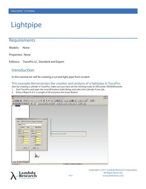
TRACEPRO ® TUTORIAL<strong>Lightpipe</strong>RequirementsModels:NoneProperties: NoneEditions:TracePro LC, Standard and ExpertIntroductionIn this tutorial we will be creating a curved light pipe from scratch.This example demonstrates the creation and analysis of a lightpipe in TracePro.Start by creating a cylinder in TracePro, make sure you have set the viewing mode to Silhouette, VIEW|Silhouette1. Start TracePro and open the Insert|Primitive Solid dialog and select the Cylinder/Cone tab.2. Enter a Major R of 2, a Length of 30 and press the Insert Button.Page 1Copyright © 2011 Lambda Research Corporation.All Rights Reserved.www.lambdares.com
TRACEPRO ® TUTORIAL<strong>Lightpipe</strong>Selecting a SurfaceTracePro uses surface and object selections for many operations.1. Select the right end of the rod using the Edit|Select|Surface menu (or Select Surface tool), use the mouse to “pick” therod end.2. When selecting the surface in the model window, it may be necessary to change the cursor to “orbit view” mode, rotatethe cylinder, then change the cursor back to “surface select” mode to pick the surface.3. Objects and surfaces can also be selected in the system tree.Page 2www.lambdares.com
TRACEPRO ® TUTORIAL<strong>Lightpipe</strong>Add a BendAdd a bend to the selected surface by revolving the face along an arc.1. Select Surface 2, then Edit|Surface|Revolve (or right-click | Revolve) to open the Revolve Surface Selection2. Enter 90 for the Angle and 25 for the bend Radius.3. The surface will be “swept” or “revolved about an axis defined by a position in space and a vector. Locate the Axis at thepoint (0,-25, 30) and define the axis to be pointing along the X axis in model space.4. Press the Revolve Surface button to perform the bend.5. You might need to decrease the size of the model to see the bend.Page 3www.lambdares.com
TRACEPRO ® TUTORIAL<strong>Lightpipe</strong>Apply a Material PropertyTracePro uses properties to “make the model optical”. Material properties define the bulk or volume data for an object, in this casethe index of refraction.1. Select the lightpipe (Cylinder 1) and open the Apply Properties Dialog with Define|Apply Properties (or right-click |Properties)2. Select the Plastic Catalog, select Acrylic and press the Apply button. You can see the Material property name by expanding the“Cylinder 1” object in the System Tree.Page 5www.lambdares.com
TRACEPRO ® TUTORIAL<strong>Lightpipe</strong>Setup a Grid of RaysNow you have an optical model ready for raytracing. This step will set up a gaussian beam in for a Grid Raytrace.1. Select Grid Source 1 in the Source Tree, then open the Grid Source dialog with Define|Grid Source. (or right-click | Define| Grid Source)2. Update the Grid Setup tab so the Outer radius is 2, the Grid Pattern is Random and the Total rays is set to 1000.You define the location of the grid with the Origin which should be set to (0,0,-0.1) as shown on the left.3. Modify the Beam Setup tab to have an Angular profile of Gaussian with 30 degree Half angles as shown on the right.Page 6www.lambdares.com
TRACEPRO ® TUTORIAL<strong>Lightpipe</strong>Trace the RaysSelect Raytrace | Trace Rays to perform the raytrace. TracePro starts by performing an Audit which updates the model with propertyinformation from the database. The output is shown below.You can turn off the rays using the Analysis|Display Rays menu or try Analysis|Ray Sorting to reduce the number of raysdrawn.Page 7www.lambdares.com
TRACEPRO ® TUTORIAL<strong>Lightpipe</strong>Setting Irradiance Map OptionsThe next step is to set the Irradiance Map Options. The options may be set at any time to modify the display of the Irradiance Plot.1. Select Surface 4, the end of the lightpipe.2. Open the Options Dialog with the Analysis|Irradiance/Illuminance Options menu, update the options as shown andpress ApplyPage 8www.lambdares.com
TRACEPRO ® TUTORIAL<strong>Lightpipe</strong>Display the Irradiance MapWith the end of the lightpipe selected you can display raytrace results. An irradiance map displays the flux per unit area over asurface.1. Open an Irradiance Map window using the Anaylsis|Irradiance/Illuminance Maps menu or press the Irradiance Map icon.2. A summary of the plot is located on the bottom of the plot. The Normalized Flux displays the ratio of the Incident Light on thesurface relative to the light emitted from the source, in this case the grid of rays.Page 9www.lambdares.com
TRACEPRO ® TUTORIAL<strong>Lightpipe</strong>Candela OptionsThe next step is to set the Candela Map Options. The options may be set at any time to modify the display of the Candela Plots.1. Open the Options Dialog with the Analysis|Candela Options menu, update the options as shown and press ApplyPage 10www.lambdares.com
TRACEPRO ® TUTORIAL<strong>Lightpipe</strong>Polar Iso-Candela PlotsCandela Plots provide information on the angular distribution of flux and are often based on “Missed Rays” in TracePro.1. Open an Irradiance Map window using the Anaylsis|Candela Plots|Polar Iso-Candela menu or press the Polar Iso-Candela icon.2. A summary of the plot is located on the bottom of the plot.Page 11www.lambdares.com