Objective methodology for simple calculation of the energy delivery ...
Objective methodology for simple calculation of the energy delivery ...
Objective methodology for simple calculation of the energy delivery ...

Create successful ePaper yourself
Turn your PDF publications into a flip-book with our unique Google optimized e-Paper software.
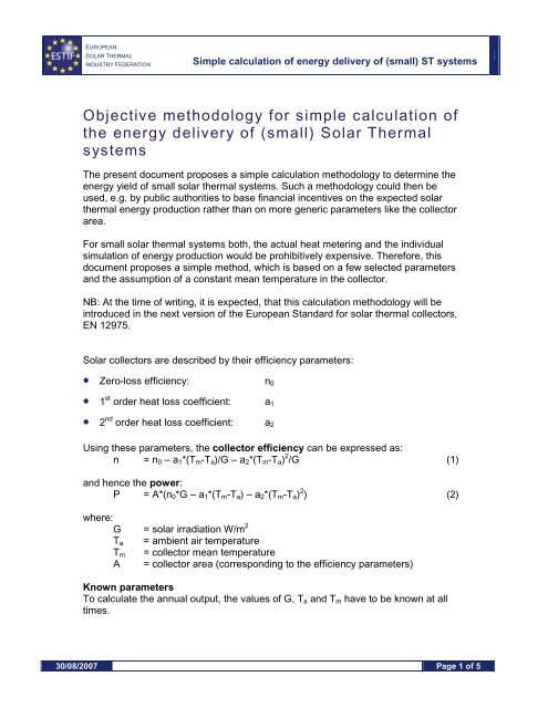
EUROPEANSOLAR THERMALINDUSTRY FEDERATIONSimple <strong>calculation</strong> <strong>of</strong> <strong>energy</strong> <strong>delivery</strong> <strong>of</strong> (small) ST systems<strong>Objective</strong> <strong>methodology</strong> <strong>for</strong> <strong>simple</strong> <strong>calculation</strong> <strong>of</strong><strong>the</strong> <strong>energy</strong> <strong>delivery</strong> <strong>of</strong> (small) Solar ThermalsystemsThe present document proposes a <strong>simple</strong> <strong>calculation</strong> <strong>methodology</strong> to determine <strong>the</strong><strong>energy</strong> yield <strong>of</strong> small solar <strong>the</strong>rmal systems. Such a <strong>methodology</strong> could <strong>the</strong>n beused, e.g. by public authorities to base financial incentives on <strong>the</strong> expected solar<strong>the</strong>rmal <strong>energy</strong> production ra<strong>the</strong>r than on more generic parameters like <strong>the</strong> collectorarea.For small solar <strong>the</strong>rmal systems both, <strong>the</strong> actual heat metering and <strong>the</strong> individualsimulation <strong>of</strong> <strong>energy</strong> production would be prohibitively expensive. There<strong>for</strong>e, thisdocument proposes a <strong>simple</strong> method, which is based on a few selected parametersand <strong>the</strong> assumption <strong>of</strong> a constant mean temperature in <strong>the</strong> collector.NB: At <strong>the</strong> time <strong>of</strong> writing, it is expected, that this <strong>calculation</strong> <strong>methodology</strong> will beintroduced in <strong>the</strong> next version <strong>of</strong> <strong>the</strong> European Standard <strong>for</strong> solar <strong>the</strong>rmal collectors,EN 12975.Solar collectors are described by <strong>the</strong>ir efficiency parameters:• Zero-loss efficiency: n 0• 1 st order heat loss coefficient: a 1• 2 nd order heat loss coefficient: a 2Using <strong>the</strong>se parameters, <strong>the</strong> collector efficiency can be expressed as:n = n 0 – a 1 *(T m -T a )/G – a 2 *(T m -T a ) 2 /G (1)and hence <strong>the</strong> power:P = A*(n 0 *G – a 1 *(T m -T a ) – a 2 *(T m -T a ) 2 ) (2)where:G = solar irradiation W/m 2T a = ambient air temperatureT m = collector mean temperatureA = collector area (corresponding to <strong>the</strong> efficiency parameters)Known parametersTo calculate <strong>the</strong> annual output, <strong>the</strong> values <strong>of</strong> G, T a and T m have to be known at alltimes.30/08/2007 Page 1 <strong>of</strong> 5
EUROPEANSOLAR THERMALINDUSTRY FEDERATIONSimple <strong>calculation</strong> <strong>of</strong> <strong>energy</strong> <strong>delivery</strong> <strong>of</strong> (small) ST systemsG and T a are wea<strong>the</strong>r data defined by <strong>the</strong> location; <strong>the</strong>ir values are (at least inprinciple) known <strong>for</strong> most European places.Assumption on T mT m is normally not known. Its value depends not only on <strong>the</strong> wea<strong>the</strong>r, but also on <strong>the</strong>load and <strong>the</strong> design and <strong>the</strong> components <strong>of</strong> <strong>the</strong> system (collector area and efficiencyparameter, storage capacity, heat losses, control, ...), i.e. on <strong>the</strong> actual system and<strong>the</strong> actual operation conditions at a given point in time.But if T m is assumed constant all <strong>the</strong> time <strong>the</strong> case is very <strong>simple</strong>: When <strong>the</strong> collectorand <strong>the</strong> location is known/specified <strong>the</strong> power output is determined at every point intime by eq. (2) below using always <strong>the</strong> same value <strong>of</strong> T m .The difficult task is now reduced to estimating a typical operation temperaturedepending on <strong>the</strong> application: At which temperature delivers <strong>the</strong> collector typicallymost <strong>energy</strong> to <strong>the</strong> system. Some suggestions <strong>for</strong> such temperatures are given intable 1.Resulting annual <strong>energy</strong> outputAssuming a constant collector temperature, <strong>the</strong> annual <strong>energy</strong> output is calculated byintegrating eq. (2) over a year including all positive contributions (as it is assumedthat <strong>the</strong> collector loop is never operating when <strong>the</strong> contribution is negative).Q annual = ∫ [A*(n 0 *G – a 1 *(T m ,constant-T a ) – a 2 *(T m ,constant-T a ) 2 )] + dtIn practise it is now easy to calculate <strong>the</strong> annual output per m 2 <strong>of</strong> a given collectoroperating at a typical mean temperature using e.g. hourly wea<strong>the</strong>r data and <strong>the</strong>collector efficiency parameters.To use this <strong>simple</strong> model to estimate real collector/system output and system savingsit is needed to:• define typical/representative collector mean operating temperatures in typicalapplications (see table 1 <strong>for</strong> suggestions)• convert collector annual output to system output• convert system output to system savingsDue to big difference from country to country (definitions/conversions depend onnational traditions <strong>for</strong> hot water and heating system, solar system type and back-upsystem type), this should be left to decision on national or even local level – but somerecommendations/suggestions are given in table 1 below.ApplicationRecommendedT m [°C] <strong>for</strong>calculatingF col-sysFactor <strong>for</strong>F sys-savFactor <strong>for</strong>F col-sav =F col-sys *F sys-sav30/08/2007 Page 2 <strong>of</strong> 5
EUROPEANSOLAR THERMALINDUSTRY FEDERATIONSimple <strong>calculation</strong> <strong>of</strong> <strong>energy</strong> <strong>delivery</strong> <strong>of</strong> (small) ST systemsannual collectoroutputconvertingcollectoroutput tosystem outputconvertingsystem outputto systemsavingsResulting factor<strong>for</strong> convertingcollector outputto systemsavingsSwimming pools 30 0,76 1,31 1,00Domestic hotwater DHW*Boiler Back-up50 0,86 1,38 1,19Domestic hotwater DHW*Eletricity Back-upCombi systemsHW/SHDistrict heatingwithout seasonalstorage50 0,86 1,00 0,8660 0,77 1,31 1,01Average returntemperaturefrom distric<strong>the</strong>ating network+ 50,95 1,05 1,00Cooling / AC 90 0,90 1,11 1,00Process heatProcesstemperature +100,90 1,11 1,00Table 1. Recommendations <strong>for</strong> typical T m ’s and factors <strong>for</strong> converting annual collectoroutput to system output and to annual <strong>energy</strong> savings using <strong>the</strong> factors F col-sys , F syssavand F col-sav . See table 2 below <strong>for</strong> <strong>the</strong> data used to make <strong>the</strong> numbers in table 1.*) Fig.1 in <strong>the</strong> end <strong>of</strong> this section indicates that using 50°C as constant temperature<strong>for</strong> DMW systems is valid <strong>for</strong> even very different climates.The factors F col-sys , F sys-sav and F col-sav are defined by <strong>the</strong> following equations:• {System Output} = F col-sys * {Collector Output}• {System Savings} = F sys-sav * {System Output}• {System Savings} = F col-sav * {Collector Output}• F col-sav = F col-sys * F sys-savF col-sys takes into account losses in <strong>the</strong> solar system:• F col-sys = {Collector Output} – {Pipe Losses} – {Extra Tank Losses})/{CollectorOutput}{Extra tank Losses} are extra heat losses due to higher temperatures in summer (andbigger volume) in a solar tank (compared with non-solar tank).F sys-sav takes into account losses in <strong>the</strong> back-up system:• F sys-sav = ({System Output}/η boiler + {Saved Stand-by Losses}/ η boiler ) / {SystemOutput}• η boiler = {Boiler Efficiency}30/08/2007 Page 3 <strong>of</strong> 5
EUROPEANSOLAR THERMALINDUSTRY FEDERATIONSimple <strong>calculation</strong> <strong>of</strong> <strong>energy</strong> <strong>delivery</strong> <strong>of</strong> (small) ST systems{Saved Stand-by Losses} can be obtained if <strong>the</strong> boiler is <strong>of</strong>f during summer.If <strong>the</strong> back-up system is electricity, η boiler = 1, and {Saved Stand-by Losses} = 0,hence:• F sys-sav = 1 in case <strong>of</strong> electrical back-upThe data used <strong>for</strong> calculating <strong>the</strong> values in table 1 are given in table 2.ApplicationPipe Losses in% <strong>of</strong> CollectorOutputExtra TankLosses in % <strong>of</strong>CollectorOutputBoilerEfficiency in %Boiler Stand-byLosses in % <strong>of</strong>CollectorOutputSwimming pools 5% 20%** 85% 10%Domestic hotwater DHWBoiler Back-up10% 5% 85% 15%Domestic hotwater DHWElectricity Back-upCombi systemsHW/SHDistrict heatingwithout seasonalstorage10% 5% 100% 0%10% 15% 85% 10%5% 0% 95% 0%Cooling / AC 5% 5% 90% 0%Process heat 5% 5% 90% 0%Table 2. Data used <strong>for</strong> calculating <strong>the</strong> values in table 1.**) The pool is here acting as “tank” <strong>for</strong> <strong>the</strong> solar system – <strong>the</strong> 20% tank lossesindicate that in very sunny and warm periods <strong>the</strong> pool is heated above <strong>the</strong> necessarytemperature level.Tm = f(Solar Fraction)908070TM (°C)605040302010020 30 40 50 60 70 80Solar Fraction (%)Tm-DKTm-GRPoly. (Tm-DK)Poly. (Tm-GR)y = 0,0193x 2 - 0,6497x + 28,95y = 0,003x 2 + 0,2291x + 13,89930/08/2007 Page 4 <strong>of</strong> 5
EUROPEANSOLAR THERMALINDUSTRY FEDERATIONSimple <strong>calculation</strong> <strong>of</strong> <strong>energy</strong> <strong>delivery</strong> <strong>of</strong> (small) ST systemsFigure 1. T m can <strong>for</strong> each climate be correlated to <strong>the</strong> solar fraction <strong>of</strong> a typical DHWsystem by finding <strong>the</strong> solar fraction at which <strong>the</strong> solar input equals <strong>the</strong> collectoroutput at T m (°C). The figure shows this function <strong>for</strong> a typical DHW system in Greeceand Denmark. The solar fraction is here defined as <strong>the</strong> fraction <strong>of</strong> solar input to <strong>the</strong>tank to <strong>the</strong> total input to <strong>the</strong> tank:Solar fraction = Solar input / (Solar input + Supplementary input).It is seen that T m = 50 °C corresponds to a solar fraction in DK <strong>of</strong> 5 3% and in Greece<strong>of</strong> 75%, which actually correspond to typical solar fractions in <strong>the</strong> two counties.30/08/2007 Page 5 <strong>of</strong> 5


![Energy [R]evolution - Greenpeace](https://img.yumpu.com/47174859/1/184x260/energy-revolution-greenpeace.jpg?quality=85)