

Numerical Back-analysis of In-situ Measurements - Plaxis
Numerical Back-analysis of In-situ Measurements - Plaxis
Numerical Back-analysis of In-situ Measurements - Plaxis

Create successful ePaper yourself
Turn your PDF publications into a flip-book with our unique Google optimized e-Paper software.
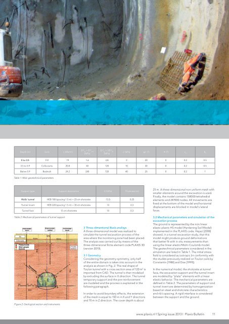
Depth (m) Soils g(kN/m 3 )E ref 50 = Eref oed(MPa)E ref ur = 3. E ref 50(MPa)c’ (kPa) j’ (°) y (°) v urK 00 to 3.5 Fill 19 1.6 4.8 2 20 0 0.2 0.53.5 to 5.9 Colluviums 20.8 40 120 10 30 0 0.2 0.5Below 5.9 Bedrock 24.2 240 720 40 25 0 0.2 1Table 1: Main geotechnical parametersSupport type Support description E (GPa) Thickness (m)Walls’ tunnel HEB 180 (spacing 1.5 m) + 25 cm shotcrete 13.5 0.25Tunnel invert HEB 220 (spacing 1.5 m) + 30 cm shotcrete 14 0.3Tunnel face 15 cm shotcrete 10 0.325 m. A three-dimensional non uniform mesh withsmaller elements around the excavation is used.Finally, the model contains 158000 tetrahedralelements and 247000 nodes. All movements arefixed at the bottom <strong>of</strong> the model and horizontaldisplacements are blocked in model’s lateralfaces.Table 2: Mechanical parameters <strong>of</strong> tunnel supportFigure 2: Geological section and instruments3 Three-dimentional <strong>Back</strong>-analisysA three-dimensional model was realized tosimulate the tunnel excavation process <strong>of</strong> thearea where the monitoring zone had been placed.The <strong>analysis</strong> was carried out by means <strong>of</strong> thethree-dimensional finite element code PLAXIS 3D(version 2010).3.1 GeometryConsidering the geometry symmetry, only half<strong>of</strong> the entire domain is taken into account in the<strong>analysis</strong> as shown in Fig. 2. The real shape <strong>of</strong>Toulon tunnel with a cross section area <strong>of</strong> 120 m 2 isimported from CAD. The tunnel is then modeledby extruding the surface in X direction. The tunneltemporary support and the pre-reinforcementare modeled and the process is explained in thefollowing paragraph.<strong>In</strong> order to avoid boundary effects, the extension<strong>of</strong> the mesh is equal to 150 m in X and Y directionsand 70 m in Z direction. The cover depth is about3.2 Mechanical parameters and simulation <strong>of</strong> theexcavation processThe ground is represented by the non linearelasto-plastic HS model (Hardening Soil Model)implemented in the PLAXIS code. Hejazi [2008]showed, in a tunnel excavation study, that thismodel might produce ground deformationsthat better fit with in <strong>situ</strong> measurements thanusing the linear elastic/Mohr-Coulomb model.The geotechnical parameters considered in thesimulation are listed in Table 1. The initial stressfield is considered as isotropic (in conformity withthe studies previously realized on Toulon soils byConstantin [1988] and Dias [1999]).<strong>In</strong> the numerical model, the shotcrete at tunnelface, the excavation support and the tunnel invertare modeled by “plate” elements with a linearelastic behavior. The mechanical parameters aredefined in Table 2. The parameters <strong>of</strong> support andtunnel invert are determined by homogenizationbased on steel and shotcrete characteristicsand rib’s spacing. A rigid interface is consideredbetween the support and the ground.www.plaxis.nl l Spring issue 2013 l <strong>Plaxis</strong> Bulletin 11


