Power Factor Controller BR7000-I (S485)
Power Factor Controller BR7000-I (S485)
Power Factor Controller BR7000-I (S485)

Create successful ePaper yourself
Turn your PDF publications into a flip-book with our unique Google optimized e-Paper software.
<strong>Power</strong> <strong>Factor</strong> <strong>Controller</strong><strong>BR7000</strong>-I (<strong>S485</strong>)<strong>Power</strong> Quality SolutionsAUTO MODE------------------cos j 0.987 INDBR 7000-I<strong>Power</strong> <strong>Factor</strong><strong>Controller</strong>1 2 3 4 5 6 7 8 9 10 11 12AutoProgramManualServiceEnterOKHELPESCcos jVersion 2.0 E , May 2013ManualVersion 2.0 - Epowerfactornextcontrollergeneration
AUTO MODE------------------cos j 0.987 IND FAUTO-MODE1 2 3 4 5 6 7 8 9 10 11 12U------------------I------------------Q223.0 V268 A107 kvarDISPLAY-MODEHARMONICS [V]2.0%BARGRAPH-MODE1.0%0%2 3 4 5 6 7 8 9 10 11 12 13 14 15 16 17CAUTIONS:!1. High voltage !2. <strong>BR7000</strong>-I may only be used indoor !3. Make sure that the discharge time set in controllermatches capacitor discharge time !Version 2.0 E, May 2013
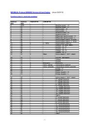
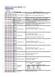
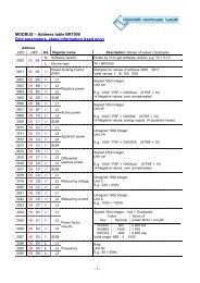
CONTENTSSection 1 General / type series and accessories 3Section 2 Installation of the controller / connection diagram 52.1 Current measurement 62.2 Programming of phase-correction2.3 Error messages: Alarm- / Message relay 7Section 3 Operating modes 7Section 4 Automatic operation / display functions 8Section 5Programming5.1 Automatic initialization 95.2 Manual programming 105.3 Programming lock 13Section 6 Manual operation / Programming of fixed stages 14Section 7 Service menu, Test run 15Section 8 Expert mode 168.1 Expert mode 18.2 Expert mode 2 18Section 9 Control principle 19Section 10 Display editor 20Section 11 Initial operation 20Section 12 Maintenance and warranty 20Section 13 Interface 21Annex: Annex 1 Troubleshouting 23Annex 2 Technical data 24Annex 3 Table of control series 25Description of control-series editorAnnex 4 Default settings 26Application Coupling of compensation systems 27Application Mixed dynamic compensation 28Cascading of controllersApplication Real current measurement 29Alarm and status notifications 30Handling-diagram / short reference 31- 2 - Version 2.0 E, May 2013
Section1 GeneralThe power factor controller <strong>BR7000</strong>-I (single phase) enlarges the product range of powerfactor control devices by a useful combination of the features known from the well-provenseries BR6000 with the advantages of a better visualization of the <strong>BR7000</strong>-series.The big graphic display enables a user-friendly programming and gives further benefitssuch as larger display in the Display-mode and the display of various parameters inbargraph-mode.With the additional “ESCAPE”-button a backward navigation in all menus is possible.The “HELP”-button allows an interactive help in the particular menu item(German/English).The controller is characterized by its user friendly operating interface via menu drivenplain text display. The display of several grid parameters, the storage of different valuesas well as the possibility of test run allow a simple error analysis and system monitoring.If required, an automatic initialization is possible which reduces the start-up operation toa minimum.RRRRRRRRRRRRRRRRRRRRRRRR12 respectively 13 switching outputs20 pre-programmed control series with self optimized intelligent control behaviorControl series editor for individual control seriesOperation and display completely menu-drivenIlluminated graphic display 128 x 64 dots4 quadrant operationAutomatic initialization possibleDisplay of several grid parameters also in large lettersDisplay of harmonics of voltage and current, also as bar graphDisplay and monitoring of temperatureMonitoring of the particular capacitor outputStorage of maximum values of grid parameters as well as switching operationsand switch-in times of particular capacitor contactorsManual/automatic operationProgramming of fixed steps or skipping of single outputs possibleZero voltage switch offError display of different states and alarm output (relay)Error storageTest run of the system with error analysisPanel-mounted instrument 144 x 144 x 53 mmFirmware update possibleVersion with interface only:additional external input (funktion programmable), e.g. for 2nd parameter setadditional freely programmable alarm relay, e.g. for fan, status notificationserial interface R<strong>S485</strong>, for controller coupling, integration into networksvisualization, programming and data processing via PC by enclosed software- 3 - Version 2.0 E, May 2013
Section 2 Installation and connection of the controllerThe <strong>BR7000</strong>-I is designed to be incorporated into the front panel of a PFC-cabinet. Itrequires a switchboard section of 138 x 138 mm to DIN 43700/ IEC 61554. The controlleris inserted from the front and is attached by means of the appended clamps. Thecontroller may be inserted only by qualified technicians and must be operated inaccordance with the specified safety regulations.Before the device is connected up, all leads and cables must be checked to ensure that nocurrent is flowing through them and the current converter must be short-circuited. Careshould be taken to ensure that the measuring voltage and current are in the correct phase2position. The measuring-current circuit must be wired with copper leads of 2.5mm . Theconnection should be set up as shown in Fig. 3. The specified safety regulations must beobserved.The measuring voltage may lie in the range from 30...440 V~ (L-N) resp. 50..760V~ (L-L)(programming of phase correction needed)The operating voltage is 110...230 VAC +/- 15%.!The coil voltage for the capacitor contactors and the measuring voltagemust be drawn from the same phase conductor, as only the measuringvoltage is monitored. (Protection against direct reconnection of thecapacitor contactors in the event of momentary single-phase powerfailure)Fig. 3: <strong>BR7000</strong>-I Connection planL1 (R)L2 (S)L3 (T)NPE<strong>Power</strong> feedsupplyvoltageVbT 2Ameas.voltageVmT 2Ameas.currentIm (5A/1A)klT 6,3ALoad side1. capacitorbranch(L3) (L2)(L) (N) L1 N k lpower factorcontroller<strong>BR7000</strong>-IUb Um ImP1P2K1ab1 2 3 4 5 6 7 8 9 10 11 12alarmrelaycapacitorcontactors 1-6capacitorcontactors 7-12- 5 -Version 2.0 E, May 2013
2.1 Current measurementWhen installing the current converter, care should be taken to ensure that the loadcurrent and capacitor-current flows through it. The outputs of the compensation networkmust be installed behind the current converter (in the direction of current flow). If the<strong>BR7000</strong>-I is connected up via sum-current converters, the overall conversion ratio isentered.!Caution !Current converter clamps shouldbe grounded on one side !Measurement via sum current converterFeed 1 Feed 2K kk KlL l LK L K LExample:C.converter 1: 1000/5AC.converter 2: 1000/5ASum-current converter: 5A+5A/5AC.converter ratio is: 2000/5AkkCurrentmeasurementBR6000ll2.2 Programming of phase-correction - e.g. connection directly L-L (400V)Adjustment of phase-correction between voltage and current in the meas. system is donein expert mode 1Example :Meas.current: L1Meas. Voltage L3-L2Phase U/I [ 90°]L1 (R)L2 (S)L3 (T)NPEsupplyvoltageVbmeas. -voltageL2-L3Meas.currentklBR6000T 2AT 2A(L) (N) L3 L2 k lUb Um Imusing meas. current meas. voltage phase-anglePreset: L1 L1 - N 0°L1 L1 - L2 30°L1 (kl) L2 - N 60°L1 L3 - L2 90°L1 L3 - N 120°L1 L3 - L1 150°L1 (kl) L1 - N 180°L1 (kl) L1 - L2 210°L1 L2 - N 240°L1 L2 - L3 270°L1 (kl) L3 - N 300°L1 (kl) L3 - L1 330°- 6 -Version 2.0 E, May 2013
2.3 Error-Messages: Alarmrelay / Message-relay*The <strong>BR7000</strong>-I is equipped with an alarm relay. Version /<strong>S485</strong> features an additional message relay.The functions may be programmed as follows:Alarm relay: Setting under Message relay: Setting under RemarkProgramming: 14 Alarm relay INTERFACE: 1 MESSAGE RELAY0 13th step Alarm relay=13.th step1 OFF OFF2 ERROR ERROR ERROR-summary report3 ERROR inverse ERROR inverse List of errors in ExpertMode 24 FAN FAN ERROR:relay closed in case of error5 Supply Supply ERROR inverse (factory setting):6 Under current Under current contact open in case of error7 Harmonic Harmonic8 Overcompensated Overcompensated9 Undercompensated Undercompensated10 Warning switch. oper. Warning switch. oper.11 Modbus-Error Modbus-Error12 MMI-Error MMI-Error13 C-defect C-defect14 Fixed step OUT ext. input triggers fixed stepAdjustment and masking of all ERRORS is possible in the ExpertMode 2. The adjustment is valid forboth relays.Section 3: Operating modesWhen the operating voltage is switched on, the <strong>BR7000</strong>-I briefly displays ist designation and softwareversion, then changes to its normal operating status (automatic operation). The active cos-phi value isalways displayed in the upper line and the currently connected capacitors are shown as sympols.AUTO MODE------------------cos j 0.987 IND1 2 3 4 5 6 7 8 9 10 11 12Active capacitorbranchesControl direction(here connected-in)further messagescompare last coverpage !Supply display(for 4-quadrantoperation)The control direction is symbolizedby a closed arrowConnecting-inConnecting-outThe connecting-in arrow is alwayslocated after the maximum possiblenumber of stages (end stop)An open arrow indicates that therequired blocking time (dischargetime) is running before an impendingswitching stepBy pressing the cursor buttons,the display of capacitor stages can be changed:Display-ModeA double arrow symbolizes fastswitching of several branchesHarmonics as bar-diagram223.0 VU------------------268 A107 kvarI------------------HARMONICS [V]2.0%1.0%0%Q 2 3 4 5 6 7 8 9 10 11 12 13 14 15 16 17By activating the ENTER-button the selected display can be stored as standard main display.
Repeated pressing of the "Operating Mode” key takes the user to the various menus:Auto operationProgrammingManual operat.ServiceExpert Mode 1Expert Mode 2Display-Editor INTERFACEback to 1Section 4 Automatic operation - display of network parameterThe <strong>BR7000</strong>-I is set to automatic operation as standard (not AUTO-INIT). Capacitorstages are then automatically connected in or out in order to reach the target powerfactor. This happens if the required reactive power is approx. 1/3 higher than the value ofthe smallest capacitor step.In automatic operation, various network parameters can be displayed by repeatedlypressing the "ENTER” key:ActionDisplayENTER 1 LINE VOLTAGE in V /%ENTER 2 APPARENT CURRENT in A /%ENTER 3 REACTIVE POWER in kvar /%ENTER 4 ACTIVE POWER in kW /%ENTER 5 APPARENT POWER in kVA /%ENTER6 DIFF. kVAR TO TARGET COSENTER 7 FREQUENCY in HzENTER 8 TEMPERATURE in °C / °FENTER 9 HARMONICS V / %, I / %Selection via arrow-keysENTER10 HARMONICS THD-V/%, THD-I/%ENTER11 Compensation power in kvarENTER12 ENERGY(kWh, kvarh, consumption, delivery)reset in: service / max.value resetENTER13 DATE - TIMEENTERSoftware versionENTER Return to: 1AUTO-MODE------------------3 REACTIVE POWER118 kvarAUTO-MODE------------------10 HARMONICS THD rel.V 1.7% I 0.8%The power value specifies the total power (3-phase) assuming symmetrical load. If nokey is pressed for 120 seconds, the display automatically returns to the operating status!Under “13 Date-Time” the date format 12h/24h setting can be changed by the arrowbuttons (only version /S).- 8 -Version 2.0 E, May 2013
Section 5Pressing theProgrammingkey once takes the user into the PROGRAMMING mode.The upper display always shows the parameter and the lower one the set value. Valuesthat can be edited are generally put into square brackets [ ]. The values are changed bypressing the é / ê keys. Subsequent pressing of the "ENTER” key stores the value andtakes the user to the next parameter.“ESCAPE” allows return to previous menu item.Description of the parameters: See the next pageTo quit programming mode in any step, press the key.5.1. Automatic initializationWith the automatic initialization the <strong>BR7000</strong>-I will automatically recognize theparameters of the PFC-system. It also serves as plausibility check and storage of theseparameters - the user only has to make very little or even no adjustments.Start of the initialization process is done from the menu point “PROGRAMMING” bypressing the button “ é”AUTO-INIT [YES] to be confirmed with pressing the ENTER button.Now either the values of the current transformer OR the value of the smallest step of thesystem have to be keyed in. The input of one of these values is absolutely mandatory.After input (confirm with ENTER) the automatic test run of the controller is executed.AUTO-INIT------------------1 CURRENT TRANSF.[ UNKNOWN ]AUTO-INIT------------------4 POWER 1.STAGE[25].00 kvarAUTO-INIT------------------START TEST3 test-runs will be performed during which all stages are being switched on and off. Allnecessary parameters are collected, evaluated and stored. Under certain circumstances3 additional test-runs may be required for a proper initialization.After successful finalization of AUTO-INIT the <strong>BR7000</strong>-I will switch to normal operation.In case of recognition of any discrepancies (plausibility) or of inaccurate connection, thedetected error will be displayed in plain text after finalization of AUTO-INIT and can beeliminated. (see possible error messages at the end of the manual). AUTO-INIT may berepeated then.- 9 -Version 2.0 E, May 2013
5.2. Manual programming (program menu)0 LANGUAGE: This selects the language of the operating menu(German, English, Spanish, Portuguese, French, RU, Cz, NL, PL, TR)1 I-CONVERTER PRIM: [ 5...13000] AThis selects the primary current of the current converter. Adjustment isvia the é / ê keys. Save and continue with ENTER2 I-CONVERTER SEC: [ 5 or 1] AThis sets the secondary current of the current converterSelection via é / ê. Save and continue with ENTER3 END STOPP: [ 12/13 resp.] switching to 13.stage in expert-mode 2By setting the end stopp, the number of active capacitor branches ismatched to the respective capacitor bank. This is done via the é / êkeys. The visible symbols of the capacitors correspond to the connectedoutputs. Preset = 12Save and continue with ENTER4 CONTROL SERIES: [ 1...20 + E ]The ratio of the capacitor branch power determines the control series,the power of the first capacitor always being assigned the value 1. Thecontrol series required for the compensation network is again selectedvia the é/ê keys. If the required control series should exceptionally notbe present (Annex 1), the user may define a special one (control series"E”).More on this point in the control-series editor in Annex 1.5 CONTROL PRINCIPLE: The control preference may be selected here:SEQUENTIAL connectionLOOP connectionINTELLIGENT loop connection (default setting)COMBINED CHOKESee Section 9 for an explanation of the various control modes.Selection with é / ê keys. Save and continue with ENTER6 POWER 1. STAGE: [ 0.01 ... 255.99 ] kvarTo determine the controller's response sensitivity, the dimensions ofthe network's smallest capacitor (stage 1) must be known. They areentered in two steps in kvar. The integral kvar values (before thecomma) are initially selected via the é / ê keys and saved withENTER. The positions after the comma are then selected, again via theé / ê keys. If the response sensitivity is being undercut, a warning willoccur ( indication of “!” in the display )Save and continue with ENTER7 TARGET COS PHI: [ 0.1 ind ... 0.1 cap ] or TAN PHI [9.0 ind ... 9.0cap]By setting the target cos phi, the power factor to be attained via the PFcorrection is defined. It is also set via the é / ê keys.Switch-over COS/TAN PHI in the ExpertMode 1: 21 ANZEIGE- 10 - Version 2.0 E, May 2013
8 MEASURING VOLTAGE [ 30 ... 760]V~Programming the measuring voltage of the system.The values programmed here always refer to the voltage at the clamps of thedevice !The voltage is selected via the é /ê keys. Save and continue with ENTER.9 V - CONVERTER RATIO [ NO / 230V ... 380kV ]When a measuring-voltage converter (e.g. for HV-measurement) is used, itsconversion ratio should be programmed here.(Input of prim.voltage is here, sec. voltage is automatically from item 8)Selection via the é /ê keys. Save and continue with ENTER.High voltageLow voltageMeas. CurrentIm (X/1A)20 kV / 400 VMeas.VoltageUmOperatingvoltageUbL1 (R)L2 (S)L3 (T)20000L1 (R)L2 (S)L3 (T)NPE100T 2AT 2AImBR 7000-IUmUb10 CONNECTING TIMEThis refers to the time between connecting the capacitors to increase themomentary network capacitance. It should be noted that in practical operation thereal connection time is affected by the discharge time (locking time).Setting range: 1 sec. ... 20 min. (long time for HV- networks)Default setting: 40 sec.Selection is performed via the é /ê keys. Continue with ENTER11 DISCONNECTING TIMEThis refers to the time between disconnecting the capacitors to reduce themomentary network capacitance.Setting range: 1 sec. ... 20 min. (long time for HV- networks)Default setting: 40 sec.Selection is performed via the é /ê keys. Continue with ENTER12 DISCHARGE TIMEThis is the time for which an individual output is blocked between connecting anddisconnecting. This blocking time has priority over connecting and disconnectingtimes. It depends on the capacitor discharge rating and thus is specified by thecompensation network. The discharge time of a conventional network withoutadditional fast-discharge resistors or chokes should be set to no less than 40seconds. For setting of a second discharge time compare 'Expert Mode' point 10Setting range: 1 sec ...20 min. Default setting: 60 sec.Selection is performed via the é /ê keys. Continue with ENTER- 11 -Version 2.0 E, May 2013
13 ALARM TEMP [ 40...85]°CThe alarm temperature programmed here is the temperature at which thecapacitor stages are disconnected in steps. The controller’s alarm relayresponds after ten minutes. (<strong>Factor</strong>y settings) At the same time the displayshows the cause of the alarm (over-temperature). If the temperature dropsagain, the required branches are automatically re-connected in steps. (<strong>Factor</strong>ysetting: 55°C)The selection is performed with the é /ê keys. Save and continue with ENTER.14 ALARM RELAYcan be programmed here for one of the following functions:ERROR = Summary report0 13th step Relay output = 13th capacitor step1 OFFS2 ERROR contact closed in case of error (except voltage sag)3 ERROR inverse contact open in case of error (factory setting)ERROR resp. ERROR inverse is a collective report andincludes the following errors:Overtemperature, Meas.voltage, Overvoltage,Undervoltage, Over- Undercompensated, Overcurrent,Harmonics, Warning switchiung operations4 FAN for external fanParameterization under “15 FAN temperaure”5 SUPPLY Message when real-power is supplied6 UNDERCURRENT Measuring current below minimum7 HARMONIC Exceeding of THD-V limit value (7%)Parameterization under “16 Harmonics”8 OVERCOMPENSATED9 UNDERCOMPENSATED10 Warning switch. oper. Exceeding of set switching operations value11 MODBUS-ERROR12 MMI-ERROR13 C-defectSection each is done with the é / ê buttons. Save/continue with ENTER- 12 - Version 2.0 E, May 2013
15 FAN TEMP* [15...70]°CInput of the switching threshold for the fan. Only active if option 'Fan' is selected16 HARMONICS (harmonic limit) [7]% (0.5 ... 25,5)%A limit for the total harmonic distortion THD-V (in%) can be entered here. Whenthis threshold is exceeded, a message is given. THD-V is the ratio of thegeometric sum of the harmonics to the fundamental.17 HARMONICSselection of harmonics for bar graph-display in Display-Mode[3. 5. 7. - 19.] Odd up to 19th (factory setting)[3. 5. 7. - 33.] Odd up to 33th[2. 3. 4. - 17.] Even and odd up to 17th18 CONTRASTAdjustment of optimal contrast for the display possible19 - 28 Programming of all values of the 2nd parameter set*only active if under „INTERFACE: 3 EXT. INPUT“ the function„2nd parameter set“ is activatedFrom factory side the values of the 2nd parameter are set equal to the ones ofthe normal parameters. By changing of particular parameters for example thetarget cos-phi can be changed here. Other cases of application are transformerswitch over or change of switching times.By applying a control voltage (110…230V) at the external input the 2ndparameter set is activated with following indicated values:19. I-transformer prim, 20. I-transformer sec., 21. End stopp, 22. Controlseries, 23. Control principle, 24. Output 1st step, 25. Target cos-phi, 26. Switchon time, 27. Switch off time, 28. Discharge time.2Marking of the values of the 2nd parameter set and the display of activationappears in the display with this symbolBASIC SETTINGS: [ NO ] ( YES / NO )When the selection is made with YES and confirmed with ENTER, all parametersare reset to the basic setting made by the PFC-system manufacturer.(Optimal network values when the controller was supplied with a complete PFCsystem).If the controller is supplied from the works, this point corresponds tothe default setting.CAUTION: All user settings are lost!5.3 Programming lockThe <strong>BR7000</strong>-I is equipped with a programming lock to ensure protection fromunauthorized or inadvertent changes to the system parameters. The lock can be activatedin expert mode1 - item9. If the lock is active, all parameters can be checked but notchanged.- 13 -Version 2.0 E, May 2013
Section 6Manual operation (initial operation, maintenance, service)Programming of fixed stagesIn manual operation, capacitor branches can be connected/disconnected in the setcontrol series and switching time - irrespective of prevailing power-line conditions.The starting condition is STOPP (no stages connected). Connections are made bypressing the é key (CAP ON). Pressing ê initially leads back to STOPP mode. Repeatedpressing of ê leads to the disconnection of stages (CAP OFF).The active operating status and active power factor are always shown on the display (selfexplanatory).MANUAL MODE------------------MANUAL MODE------------------MANUAL MODE------------------STOP 1.000 CAP ON 0.871 CAP CAP OFF 0.871 CAP1 2 3 4 5 6 7 8 9 10 11 12 1 2 3 4 5 6 7 8 9 10 11 12 1 2 3 4 5 6 7 8 9 10 11 12device-Stop connection of steps disconnection of stepsPressing ENTER takes the user to the menu point "Programming of fixed stages”.Normally, all stages are programmed for automatic operation (default setting).MANUAL MODE------------------MANUAL MODE------------------MANUAL MODE------------------C1 - [AUTO] C1 - [ FIXED] C1 - [OFF]1 2 3 4 5 6 7 8 9 10 11 12 1 2 3 4 5 6 7 8 9 10 11 12 1 2 3 4 5 6 7 8 9 10 11 12In special cases, all controller outputs (C1 - C12) may be permanently defined insuccession (continued switching via ENTER) for the following statuses:AUTO: Automatic (normal) operationThe relevant output is marked by a capacitor symbol.FIXED: The output is continuously connected, e.g. for fixed PFC. The output ismarked by an underlined capacitor symbol.OFF: The output is continuously disconnected - e.g. for temporarily disconnecting adefective capacitor. The capacitor symbol for this output is faded out. Underliningappears.The active stage is blinking. The required status is set via é /ê. By pressing ENTER, theuser saves this step and moves to the next stage.The programmed statuses for the outputs also remain visible on the display in automaticoperation.After the required settings have been made, pressing the "Operating Mode” key takes theuser to the next menu ("Service”) or further to "Automatic Operation”.- 14 -Version 2.0 E, May 2013
Section 7Service menuThe service menu is reached by the operating-mode key.The stored maximum values of the network parameters can be displayed here as well asthe number of switching operations of the individual capacitors and their operating time.The desired stages [in square brackets] can be selected via the arrow keys.* In Version /<strong>S485</strong> the max.values are stored including time-stamp!In addition, a fault memory is available, in which the last 40 fault states of the system arestored with fault code and in plain text. (This allows, for example, capturing short livedevents of overtemperature or overvoltage)ActionDisplayENTER 1 min/max. VOLTAGE in VENTER 2 max. REACTIVE POWER in kvarENTER 3 max. ACTIVE POWER in kWENTER 4 max. APPARENT POWER in kVAENTER 5 max. TEMPERATURE in °C / °FENTER 6 max. THD - V / THD - I in %ENTER 7 RESET the maximum and energy valuesENTER 8 SWITCHING OPERATIONS C [1] - ...+/- to C [12]ENTER 9 OPERATING TIME C [1] - ... in h+/- to C [12]ENTER 10 ERROR MEMORY E [1] - .... in plaintextENTER11 ERROR MEMORY RESETENTER12 TEST RUNENTER13 C-POWER (only after a test-run or AUTO-INIT)ENTER Back to 1TEST-RUNThis menu point allows the user to check the settings of the PFC controller. After activationof the test run, the controller switches each stage on and off successively and calculatesthe output of the capacitors connected (this procedure is done three times to eliminatepossible errors). The values calculated are stored and can be retrieved in the followingmenu item (C-POWER). At the same time, a plausibility check is conducted with the valuesprogrammed.Discrepancies are displayed in plain text afterwards. The following errors can bedisplayed:- No measuring voltage present- Measuring voltage too high - check programming- Measuring voltage too low - check programming- No measuring current? - Short circuit link in current transformer?- Phase angle current transformer? k/l or phase transposed ?- Current transformer ratio / 1. Step power wrong ?- Control series? - check programming- End stop? - check programming- Capacitor defect or wrong power inputNote: The results displayed are messages intended to help the user trace the cause of theerror. Final evaluation remains the responsibility of the user. Under complicated (high loadfluctuations) grid conditions, 100% error recognition cannot be guaranteed.- 15 -Version 2.0 E, May 2013
Section 8.1 Expert mode 1The expert mode is meant for the adjustment of values which normally should not bechanged. As a protection against mal-operation this level has an access code.<strong>Factor</strong>y setting: “6343” The password can be changed in point 22 of expert mode 1.1 PASSWORD ???? (<strong>Factor</strong>y setting: 6343)2 BASIC SETTING NEW [NO] (available: NO/YES)Storage of active programming as a new basic setting (usually performed by thePFC-system manufacturer).Caution: The original values are overwritten in the process!3 SWITCHING OPERATIONS RESET [NO] (available: NO/YES)The stored switching operations of all capacitor stages are reset to zero. Caution: Noinformation is then available about the switching frequency of the stages and thusthe status of the network. (Reset of individual stages in Expert-mode 2 )4 OPERATING TIME RESET [NO] (available: NO/YES)The stored operating times of all outputs are set to zero.(Reset of individual stages in Expert-mode 2 )5 INTEGRATION TIME [1] s (1...255 sec.)The integration time (the time required to form the mean values of ameasurement) can be changed for special applications.6 SWITCHING POWER max [100] kvar (multiples of the smallest stage)This factor specifies the maximum power which may be switched in one switchingstep. It can be used to control the intelligent control system, which switches severalstages as a function of the power-factor requirement.(<strong>Factor</strong>y setting: 4 times the power of the first stage)7 SWITCH.TRIGGER IND [66]% (30...100%)Threshold for switching ON of next stage. Should not be changed in the normal case!8 SWITCH.TRIGGER CAP [66]% (30...100%)Threshold for switching OFF next stage. It should not be changed in the normal case!9 OPERATING LOCK [NO] (NO / YES)10 SWITCHING OPERATIONS WARNING [50000] (1000 ... 255000)After an output has performed this number of switching operations, a warningmessage is displayed. ( Abrasion of capacitor contactors and capacitors)11 FAST DISCHARGE [NO] (NO or X for the desired stages)If only some stages of a network are equipped with fast discharge equipment, thosestages can here be indicated with X. In this case, the desired discharge time for thesestages can be specified in the next menu point.12 DISCHARGE TIME[1] s (1s ..programmed normal discharge time)Only available when fast discharge is programmed. The specified discharge time isthen also included in the normal display.- 16 -Version 2.0 E, May 2013
13 PHASE I 0° Adjustment of current phase positionSelection of phase of current transformerAdjustment with é / ê keys14 PHASE V 0° Adjustment of voltage phase position:Between which conductors has the measuring voltage of thecontroller been connected: L-L resp. L-N of all phasespossible. Adjustment with é / ê keysPhase correction between voltage and current in the measuring system. (refer p.6)15 C-TEST [YES] ( YES / NO)The power of the particular capacitor stage is calculated during each switchingoperation and compared with the stage output of the capacitor. If the result variesfrom the nominal value, an error message is generated. This test can be stoppedhere.16 C-FAULT [40] % (10...75 %)The deviation from the rated value of the capacitor, for which a fault message isgenerated, can be specified here (see point 14)17 TEST ATTEMPTS [6] ( 2...9)When at least this number of successive measurements has resulted in a fault in thecapacitor power, a C-fault message is output.18 OUTPUT 1. STEP [0...255] (0...2550)The range for entering the stage output can be increased to [0...2550] here(e.g. for high-voltage measurement)19 CONTROL [3] PHASE ( 3 / 1 )The measuring system of the controller is based on a single phase measurement.3-phase CAP (factory setting): The measurement is converted and all outputs aredisplayed 3-phase (presuming symmetry in the grid).1-phase CAP: Display and control is only performed for the measured 1-phase value(for example 1-phase compensation in non-symmetric grids)3-phase IND: set-up of an inductive compensation with reactors possible (3- phase)1-phase IND: set-up of an inductive compensation 1-phase3-phase C/I : Mixed compensation possible (CAP/IND)1-phase C/I : (Realization according separate application solution)20 SUPPLY Setting of the controller in case supply of electric power takes place(1) --- (no reaction) factory setting(2) switch off stepwise(3) total switch off21 DISPLAY [cos j] (cos j / tan j)Switch over between cosinus or tangens j in the display (all menus)22 PASSWORD ?The password for ExpertMode can be changed here. All combinations of lettersand figures are possible27 ERROR - DISPLAY BACKLIGHTIf an error or warning message appears in the display -the backlight can changeto red light for better attention. Here a modification is possible.(OFF/ white/ red/ pink)
Section 8.2. Expert mode 2The additional 2nd expert mode includes all messages for operation, warning and errorwhich are displayed by the <strong>BR7000</strong>-I. Here they may be deactivated separately. Whendeactivated, the indication of the message in the display as well as possible activation ofthe relay or effects on the control behavior are suppressed.Additionally, switching operations and operation times of the capacitors can be reset.1 PASSWORD ???? (<strong>Factor</strong>y setting: 6343)Changing of code is possible in ExpertMode1 / item 20Activation of particular operation, warning and error messages - s. above:Meas.-voltage; Overvoltage; Overcompensated; Undercompensated; Harmonics!;Overtemperature; Overcurrent; Undervoltage; Switch.Operations!; Undercurrent;Modbus-Error; MMI-Error; Remote-disconnect; Remote-stop; Remote-connect;MODBUS-remote; Current?; Overload equip.;External Error; C-Error Off; Auto-Init-Error2 ERROR ME.RELAY [10] min. (1...255min.)Time after which the alarm relay will respond3 UNDERVOLTAGE [50] % (20 ...100 %)meas. voltage below this threshold will switch OFF allstages at the same time4 OVERVOLTAGE [130] % (105 ...140 %)meas. voltage above this threshold will switch OFFthe stages step by stepIf the measure voltage returns to the permissible range,the stages will switch ON again.5 FREQUENCY [40...80 Hz] (50Hz / 60Hz)Measurement by the controller is done automatically in grids of 40 … 80 Hz.In grids with extremely poor voltage quality it is recommend to select a fixfrequency (50 or 60 Hz) to avoid measuring errors due to voltage sags.6 SWITCH. OPERATIONS C 1 RESET [NO] (YES/NO)toC12 RESET [NO] (YES/NO)Reset of switching operations of particular capacitors possible,e.g. after replacement of particular capacitors or contactors19 OPERATION TIME C 1 RESET [NO] (YES/NO)toC12 RESET [NO] (YES/NO)Reset of operation time of particular capacitors possible,e.g. after replacement of particular capacitors- 18 -Version 2.0 E, May 2013
Section 9Control principleThe control response of the <strong>BR7000</strong>-I can be selected in programming mode. In principle,the controller has four different control modes:1. Sequential connectionIn sequential connection, the required capacitor stages are successively connectedand disconnected in stages (last in - first out). The ranking of each step alwayscorresponds to the power of the smallest stage.Advantage: Exact definition of the next capacitor to be connected in each caseDisadvantage: Long settling time, high switching frequency of the small stagesIn order to shorten the settling time, the controller switches several stagessimultaneously for a large power-factor requirement. This applies to allcontrol types. The maximum dimensions of the simultaneously switchingbranches can be changed in expert mode. If the value of the smallest stageis pre-selected, the conventional sequential connection is obtained.2. Loop connectionIn this variant, the controller operates in loop mode (first in - first out) whichminimizes the wear on the capacitor bank, i.e. where stages are of equivalentdimensions, the stage which was disconnected for the longest period of time isalways connected next.Advantage: Balanced utilization of equivalent stages and thus an increasedoperating life of the capacitor bank.Disadvantage: This mode can only be used in control series with groups of the samestage power and long settling time, as every switching step corresponds to the valueof the smallest stage.3. Intelligent loop connection (default setting )The intelligent control principle combines the advantages of the network-sparingloop connection (first in - first out) with a much faster settling time, even for largeload skips, and reaches this goal with the fewest possible switching operations of thecapacitor stages. The optimized time response is achieved by the simultaneousswitching of several or larger capacitor groups as a function of the missing powerfactor in the power line. Both the number of real switching frequencies of thecapacitors as well as the turn-on times of the branches are considered.Advantage: Reaches the target cos phi in a fast-optimized settling time with a lowswitching frequency of the capacitors.4. Combined de-tuning (special case for combined de-tuned banks)Within a combined de-tuned application, 2 adjoining equal steps are switched withjust one joint choke. This pairwise de-tuning requires an appropriate closed controlseries (i.e. 1:1:1:1..., 1:1:2:2..., 1:1:2:2:4:4... or similar)The condition for the switching behavior is defined in such a way that the number ofactivated odd steps is always greater than or equal to the number of activated evensteps. The controller complies with the requirements of the control regime whilelargely conforming to the intelligent switching behavior.The particular capacitor steps are permanently monitored. In case of a defectcapacitor or higher deviation from the nominal output the capacitor will bedisplayed inverted.- 19 -Version 2.0 E, May 2013
Section 10Display-EditorThe Display-editor is reached by activation the operation button.In the Display-editor a selection of measuring values can be performed which shall bedisplayed in the Display-mode (s. chapter 3/ page 7)Out of the available measuring values shown below 3 values can be selectedsequently which then are available in the Display-mode as large letters. Selection isdone by the arrow-buttons, confirmation with ENTER:1 Grid voltage2 Apparent current3 Reactive power4 Active power5 Apparent power6 Difference reactive power7 Frequency8 Temperature9 THD-V10 THD-I11 Cos Phi12 Tan Phi13 --- (no display)DISPLAY-EDITOR------------------1.DISPLAY [ 1][ LINE VOLTAGE ]Example: Display in DISPLAY-MODESelected parameters:1. Grid voltage2. Apparent current3. Reactive powerU------------------I------------------Q223.0 V268 A107 kvarNote:Even in Display-Mode the <strong>BR7000</strong>-I will continue to operate as P.F.controller in thebackground with all functions programmed!Section 11Initial operationThe controller must have been installed before being set up and operated.All network-specific parameters are fully programmed as described in section 5(Programming) by being entered in sequence and stored. The controller is then set toautomatic operation with the operating mode key. It is now ready for operation.Section 12 Maintenance and warrantyThe <strong>BR7000</strong>-I should need no maintenance if the operating conditions are observed.However, it is recommended that a functional check of the controller be performed inconjunction with the regular checking of the capacitor bank. In the event of anyinterventions in the controller during the warranty period, all warranty claims lapse.- 20 -Version 2.0 E, May 2013
Section 13: Menu INTERFACEThe <strong>BR7000</strong>-I is optionally equipped with a R<strong>S485</strong>-interface, an internal clock, a potentialfree external input (110 … 230 V) and an additional message relay. Therefore thefollowing functions are only available for version /S:1 MESSAGE RELAY [1]Functions and settings see section 2.3 Error messages (p.7)2 FAN TEMPERATUREInput of switching threshold, when message relay = FAN has been selected.3 EXTERNAL INPUTThe function of the external input (110..230 V) can be selected here: (Not activeif message relay is programmed as “External” or „Remote control“.[0] - OFF[1] - 2nd parameter setActivation of the input in this operation mode releases the 2nd parameterset featuring the following settings: 19/20 I-transformer; 21 End stop;22 Control series; 23 Control principle; 24 Output 1st step;25 Target cos-phi; 26-28 Switching times[2] - EXTERNAL ERRORIn this operation mode the activation of the input causes a controlledswitch off of all steps (remote switch off)[3] - Q-OFFSET By activating of the input in this operation mode an additionalcapacitive output is switched on independent from target cos-phi andcontrolling (value in Offset-output programmable).[4] - Coupling operation parallel – Coupling operation of two systems, the inputreceives a signal of the coupling switch between the systems, the systemssymmetrically (parallel) switch on the steps.[5] - Coupling operation serial – Coupling operation of two systems, the inputreceives the signal of the coupling switch between the systems, thesystems sequentially switch in the steps (first system 1, then system 2)[6] [INPUT FIXED STEP]4 OFFSET LEISTUNG (Fixed power step) – only if external input on Q-OFFSET!Input of reactive power value that is added when activating the input to therequired reactive power.5 ... 9 Adjusting of internal clock (hour, minute, date)10 PROTOCOL-----MODBUS KTRMODBUS RTU Modbus-protocol for individual usageASCII OUT Transmitting of grid-values as ASCII-Data,permanent sequential output of:U, I, Q, P, S, switched steps(display ”XXX---------” = 3 active steps)MASTER MMI Adjustment in case of real current measurementwith MMI6000/7000 (s. application p. 29)EXTERNAL Usage of an external measuring device (MMI6000/MMI7000).The values of this device are used for display and controlling.SLAVE HYBRID Operation mode as slave in hybrid-systems (s. page 28)SLAVE MODE Coupling of several controllers via interface (s. page 28)MASTER MODE see above
Depending on the selected protocol the following settings may be partially deactivated:11 BAUDRATE Baudrate 9600...256000 adjustableParity NONE, ODD, EVEN selectable12 ADRESS [1] (1...255)13 Number MMI [1] (1...9) Number of connected MMI14 Type of measuring device (MMI6000 / MMI7000 / UCM-5)15 Number of <strong>BR7000</strong>-I (1...4) Connected devices during cascading16 ASCII transmit. interval [10] sec. (1-255) Repeat. time ASCII transmission17 Separator (for ASCII Protocol)Selection HT; LF/CR; SP; CR/LF; Minus; CSVFollowing functions can be realized via the interface:RRRRRRParameterization of the controller via PCRemote read out of the grid parameters, storage and display via PC-software<strong>BR7000</strong>-SOFT during online operationUsage as system interfaceSelection MODBUS or ASCII (see above)Usage with accessory MMI6000/MMI7000 for real current or remote measuringConnection of system accessory (e.g. datalogger)Instructions for bus wiring when using the interfaceRRRFor bus wiring screened cable has to be used!The bus wirings (incoming and outgoing leads) always have to be applied directly tothe device (no branch boxes)!In the devices at the end of the busses the terminating resistors integrated in thedevice have to be activated (DIP-switch ON).Connecting plan INTERFACE:ext. Input Messagerelay110...230VBus-ConnectionPE AB Gnd1 2Switch forterminating resistorEXT. INPUT INTERFACE RS 485(L) (N) L3 L2 k lSERVICE PLUGVb Vm Im- 22 - Version 2.0 E, May 2013
Annex 1: TroubleshootingFaultCheck / SolutionAt target cos phi=1 and inductive load,switch-off or connection of capacitor inthe corrected lineSupply / Drawing mismatchedWrong line cos phi is displayedCheck terminals of the measuring voltage andcurrent (l and k)!Check phase positionSee aboveDisplay:"UNDER CURRENT”Display: "OVERCURRENT”Alarm relay: after 10 min.Display: "UNDERCOMPENSATED”Alarm relay: after 10 min.Display: "OVERCOMPENSATED”Alarm relay: after 10 min.Display: "MEASUREMENT VOLTAGE ???”Alarm relay: after 10 min.Display: "OVERTEMPERATURE”Alarm relay: after 10 min.Stages are disconnected for an inductiveline or connected for a capacitive lineCurrent in measuring range?Line interruption?Wrong current-converter factor?Current transformer short-circuited?Check current-converter ratioGo through measuring current rangeCheck connection and phase position!All stages connected - target cos phi notreached: compensation network sufficientlydimensioned?Check connection and phase position!Capacitive grid, although all stagesdisconnectedNo measurement voltage!Cabinet temperature too high: Outputs areswitched off in stages irrespective of power-lineconditionsIf a target cos phi is set which deviates from 1despite an inductive line load, the display
Annex 2:Technical dataType seriesOutputsLanguagesSwitching power of relay outputsNumber of active outputsOperation and displayNumber of control seriesUser-defined control seriesControl principleAuto-InitOperating voltageMeasuring voltageMeasuring current<strong>Power</strong> drawnSensitivityTarget cos phiConnecting timeDisconnecting timeDischarge timeFixed stages/ skipped stagesAlarm relayNo-voltage triggeringDisplay of power-line parametersStorage of maximum valuesStorage of switching numberStorage of operating timeTemperature measurement rangeError memoryAccuracyHousingWeightOperating ambient temperatureProtection type to DIN 40 050Safety guidelinesSensitivity to interference(industrial areas)<strong>BR7000</strong>-I12 (13)D / E / ES / RU / NL / CZ / PL / F / PT / TR250 VAC, 1000 WProgrammableIlluminated graphic display, 128x64dot201Sequential connection, loop connection orself-optimized switching responseFour-quadrant operationYES110...230 VAC +/-15%, 50 / 60Hz30...440V~ (L-N) resp. 50...760V~ (L-L)X : 5 / 1A selectable< 5 VA20 mA0.1 inductive to 0.1 capacitive adjustableSelectable from 1 sec ... 20 min.Selectable from 1 sec ... 20 min.Selectable from 1 sec ... 20 min.ProgrammableStandardStandard<strong>Power</strong> factor, voltage, apparent current,frequency, reactive-, active-, apparent power,missing kvar, temperature, harmonicsVoltage, reactive power, active power, apparentpower, temperature, THD-V, THD-IYes, each output, individual reset possibleYes, each capacitor, individual reset possible-30°C ... 100°CLast 40 error states are storedCurrent, voltage: 1%Reactive-, active-, apparent power: 2%Switchboard-integrated housingDIN 43 700, 144 x 144 x 53 mm1 kg-20 to +60°CFront: IP 54, Rear: IP 20IEC 61010-1:2001, EN 61010-1:2001EN 50082-1:1995IEC 61000-4-2: 8kVIEC 61000-4-4: 4kV- 24 -Version 2.0 E, May 2013
Annex 3: Table of control seriesNo.1234567891011121314151617181920"E"Control series1 : 1 : 1 : 1 : 1 : 1 : 1 : 1 : 1 : 1 : 1 : 11 : 2 : 2 : 2 : 2 : 2 : 2 : 2 : 2 : 2 : 2 : 21 : 2 : 3 : 3 : 3 : 3 : 3 : 3 : 3 : 3 : 3 : 31 : 2 : 3 : 4 : 4 : 4 : 4 : 4 : 4 : 4 : 4 : 41 : 2 : 4 : 4 : 4 : 4 : 4 : 4 : 4 : 4 : 4 : 41 : 2 : 3 : 6 : 6 : 6 : 6 : 6 : 6 : 6 : 6 : 61 : 2 : 4 : 8 : 8 : 8 : 8 : 8 : 8 : 8 : 8 : 81 : 1 : 1 : 1 : 2 : 2 : 2 : 2 : 2 : 2 : 2 : 21 : 1 : 1 : 1 : 1 : 6 : 6 : 6 : 6 : 6 : 6 : 61 : 1 : 2 : 2 : 2 : 2 : 2 : 2 : 2 : 2 : 2 : 21 : 1 : 2 : 2 : 2 : 4 : 4 : 4 : 4 : 4 : 4 : 41 : 1 : 2 : 2 : 4 : 4 : 4 : 4 : 4 : 4 : 4 : 41 : 1 : 1 : 2 : 2 : 2 : 2 : 2 : 2 : 2 : 2 : 21 : 1 : 2 : 3 : 3 : 3 : 3 : 3 : 3 : 3 : 3 : 31 : 1 : 2 : 4 : 4 : 4 : 4 : 4 : 4 : 4 : 4 : 41 : 1 : 2 : 4 : 8 : 8 : 8 : 8 : 8 : 8 : 8 : 81 : 2 : 2 : 3 : 3 : 3 : 3 : 3 : 3 : 3 : 3 : 31 : 2 : 3 : 4 : 4 : 8 : 8 : 8 : 8 : 8 : 8 : 81 : 2 : 2 : 4 : 4 : 4 : 4 : 4 : 4 : 4 : 4 : 41 : 2 : 2 : 2 : 4 : 4 : 4 : 4 : 4 : 4 : 4 : 4Control-series editorLoop connectionPossiblePossiblePossiblePossiblePossiblePossiblePossiblePossiblePossiblePossiblePossiblePossiblePossiblePossiblePossiblePossiblePossiblePossiblePossiblePossiblePossibleControl -series editor (programming up to a rating of 30)The control-series editor allows the user to simply define his/her own control series if therequired control series is not available for any reason.The last control series - Control Series E - is selected by pressing the "Programming” key(point 4: Control series) and confirmed with ENTER. This leads to the insertion of anadditional menu point in the main menu -> the control-series editor. It may be reachedvia the "Operating Mode” key.AutomaticProgrammingControl serieseditorManual operationServiceIn the control-series editor, all stages can be set in succession to the desired value withthe selection keys é / ê. The next stage in each case is reached by pressing ENTER.In the control series editor, the various steps may be programmed up to a rating of 30 (!).The rating >9 is indicated in the display as follows:10=A, 11=B, 12=C, 13=D, 14=E, 15=F, 16=G .... 30=UALL control series can be generated (even downwards). The customer will decidewhether the generated control series is of sense.The maximum number of stages can be limited by a programmed END STOPP < 12.- 25 -Version 2.0 E, May 2013
Annex 4: Default settingsNote: The following values for the default settings apply only if the controller is supplieddirectly from the manufacturer. Otherwise, these values may have been replaced bysettings made by the manufacturer of the compensation network (optimal values for therelevant network).No.ParameterDefault settingProgrammed values of thissystem (to be entered bymanufacturer or operator)0123456789101112131415161718LANGUAGEI CONVERTER prim.I CONVERTER sec.END STOPPCONTROL SERIESCONTROL PRINCIPLEPOWER 1. STAGETARGET COS-PHIMEASURING VOLTAGEV- CONVERTER RATIOSWITCH- IN TIMESWITCH- OFF TIMEDISCHARGE TIMEALARM TEMP.MESSAGE RELAYTEMP. FAN ONHARMONICS THD-VHARMONICS bar diagramCONTRASTENGLISH1000 A5 A121INTELLIGENT25.00 kvar0.98 IND230 V L-N- NO -40 sec.40 sec.60 sec.55 °CFAN30 °C7,0 %3. 5. 7. - 33.7Capacitor stagesPassword Expert-mode1/2Integration timeTrigger valueAUTO63431 sec.66%Max.simult.switch.powerOperating lockSwitch.operations warningFast dischargePhase shift U/IC - TestC - FailTest Attempts<strong>Power</strong> 1. stageControlDisplay power-factorProtocol*Baudrate*Adress*Device-type*Number of <strong>BR7000</strong>-I*ASCII interval*4 x smallest stage- NO -50,000- NO -0 °- YES -40 %60...255 kvar3 - phaseCos PhiModbus-RTU9600/None1MMI7000110 sec.* version with interface only- 26 - Version 2.0 E, May 2013
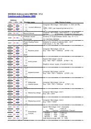
AUTO MODE------------------cos j<strong>Power</strong> Quality Solutions0.987 IND1 2 3 4 5 6 7 8 9 10 11 12AUTO MODE------------------cos j<strong>Power</strong> Quality Solutions0.987 IND1 2 3 4 5 6 7 8 9 10 11 12Applikation:Coupling of two PFC-systems using 2 PF-controllers <strong>BR7000</strong>-IThe coupling of two compensation systems via the interface of PF-controllers <strong>BR7000</strong>-I offersfollowing advantages:- no sum current transformer and no current transformer switching required- easy installation, real dynamic compensation of both compensation systemsFeed 1 Feed 2Trafo 1 Trafo 2Ct1X / 5ACouplerCt2X / 5AConsumer (1)ext. input (110...230V~)Interface(RJ45)LAN-cable (CAT5/CAT6)Interface(RJ45)Consumer (2)<strong>BR7000</strong>-I(Master)<strong>BR7000</strong>-I(Slave)Capacitor system 1 Capacitor system 2Application example:Two separate systems operate at two transformers; a coupling via a coupling switch exists betweenboth systems1) Coupling is open: Both systems work completely independent.2) Coupling is closed: Due to controller coupling, the two PFC systems are operated in PARALLEL(symmetrically) or in SERIES (as extension).Undesired interactions of the compensation system are avoided during operation at a commonbus bar (oscillation).Description:During controller coupling each controller measures its respective current. The measuring values ofreactive power difference are transmitted via interface to the „Master“. The “Master” controls andsynchronizes the switching of both controllers. No additional installation required.Installation:The coupling of the 2 PF-controllers <strong>BR7000</strong>-I/<strong>S485</strong> is done via interface (RJ45 plug) using a standardLAN-cable CAT5 . The 110…230~ signal “Coupling switch closed” has to be conducted to the potentialfree external input of a controller ( “Master”).Programming:1. “Master”: Menu INTERFACE /3 EXTERNAL INPUT: COUPLING PAR. (systems will switching symmetrically) ORCOUPLING SER. (systems will switching one after another)10 PROTOCOL: COUPLING MODE11 BAUDRATE: free (the same at each device)2. <strong>Controller</strong> of 2nd system: Menu INTERFACE/10 PROTOCOL: MODBUS RTU; 11 BAUDRATE: equal to Master-controller; 12 ADRESS: 1No additional settings are required.- 27 - Version 2.0 E, May 2013
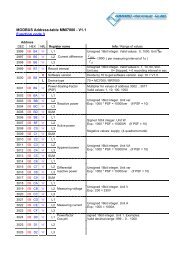
AUTO MODE------------------cos j<strong>Power</strong> Quality Solutions0.987 IND1 2 3 4 5 6 7 8 9 10 11 12AUTO MODE------------------cos j<strong>Power</strong> Quality Solutions0.987 IND1 2 3 4 5 6 7 8 9 10 11 12AUTO MODE------------------cos j<strong>Power</strong> Quality Solutions0.987 IND1 2 3 4 5 6 7 8 9 10 11 12AUTO MODE------------------cos j<strong>Power</strong> Quality Solutions0.987 IND1 2 3 4 5 6 7 8 9 10 11 12AUTO MODE------------------cos j<strong>Power</strong> Quality Solutions0.987 IND1 2 3 4 5 6 7 8 9 10 11 12AUTO MODE------------------cos j<strong>Power</strong> Quality Solutions0.987 IND1 2 3 4 5 6 7 8 9 10 11 12Annex 4: Mixed dynamical compensation system and cascading controllersA mixed dynamical compensation system implements economically the advantages of a dynamic fastnetwork. (Fast changing loads are compensated dynamically and basic loads / slowly changing loadsare compensated conventionally)For designing a mixed-dynamical compensation system a special controller was developed. TheBR6000-T6R6 supports up to 6 transistor-outputs (for triggering thyristor modules) and additional 6relay-outputs for standard capacitor contactors.Please compare the separate manual.In case more than 6 dynamical and 6 conventional stages or more than 12 standard-stages arerequired, the following applications are supported.Variant 1:Hybrid-system with one dynamical and 1...2 standard PF-controllers up to 36 outputs<strong>BR7000</strong>-T bis zu 2 <strong>BR7000</strong>-I/<strong>S485</strong>(for dynamical steps)(for conventional steps)Menu: PROGRAMMINGMenu: INTERFACE2 CONTROL-MODE: 7...14 Protocol: [Slave Hybrid]Baudrate: [38400/NONE]Adres:[1]Adres:[2]LAN-cable (CAT5/CAT6)AdapterCV-1xRJ45-BR6000LAN-cable (CAT5/CAT6)<strong>BR7000</strong>-T<strong>BR7000</strong>-I/<strong>S485</strong><strong>BR7000</strong>-I/<strong>S485</strong>Variant 2:Extended systems with up to 48 outputs by cascading of 2...4 pcs. <strong>BR7000</strong>-I/<strong>S485</strong>(all controllers will switch symmetrically)Programming in menu “INTERFACE”10 PROTOCOL: [Master Mode] [Slave Mode] [Slave Mode]11 BAUDRATE: [38400/NONE] [38400/NONE] [38400/NONE]12 ADRESS: [1] [2]15 NUMBER..: [2] (1...4)LAN-cable (CAT5/CAT6)AdapterCV-1xRJ45-BR6000LAN-cable (CAT5/CAT6)<strong>BR7000</strong>-I/<strong>S485</strong> <strong>BR7000</strong>-I/<strong>S485</strong> <strong>BR7000</strong>-I/<strong>S485</strong>- 28 -Version 2.0 E, May 2013
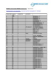
Multi-MeasuringProgramEnter1 2 3 4 5 6 7 8 9 10 11 12Application: Capacitor current monitoring using MMI6000ApplicationFor permanent current monitoring inside the compensation system the MMI6000 is recommended asan accessory for the <strong>BR7000</strong>-I. This measuring device is able to determine the sum current of thecomplete PFC system as well as the current of single capacitor branches.By monitoring the current of the installed capacitors, extraordinary grid conditions (e.g. harmoniccurrents which may cause an overload of capacitors) can be identified. In such a case, the power factorcontroller switches off the relevant compensation stages as long as the extraordinary situationcontinues. Monitoring of the capacitor current also means monitoring of the capacitor condition(damages, aging …) and thus gives the opportunity to avoid consequential damages.The MMI6000 will improve the reliability and safety of a PFC-system.Method of operation:The MMI6000 measures the sum current inside the PFC system. For this a current transformer has to beinstalled at the power input of the compensation system. During each switching operation, the actualcurrent change is measured and compared to the rated current of the switched capacitor(s). Inbetween the switching operations the current of the complete system is monitored.In case the current of a step is too high (default +50%), this step is switched off. The <strong>BR7000</strong>-I displayshows an inverted capacitor symbol. The current is further on checked periodically is the ratedcurrent reached again, the step is reactivated.Is the sum current of the complete PFC system too high, stages are switched off one after another andalarm relay is set. Periodical measurements are performed to check whether the current reaches thenominal value again. If so, the step is reactivated.Settings MMI6000:Settings <strong>BR7000</strong>-I:- Operation mode: Coupling MMI-BR6000 Menu: INTERFACE- Grid: 3-phase - 10 Protocol: MASTER-MMI- 11 Baudrate- 13 Numbers of MMIExpert-mode 1:- 15 C-Test: YES- 16 C-Error (+/- 50%)(setting of switching threshold)Principle circuit diagram:consumerMMI6000capacitor system with <strong>BR7000</strong>-IL1L2L3N<strong>Power</strong> Quality SolutionsAUTO MODE------------------cos j 0.987 INDM M I - 6000InterfaceCAUTION:Interface connection R<strong>S485</strong>For the bus-connection a shielded cable has to be used!Bus-connections (in and out) have always to be made directly to the relevant device!The terminating resistors inside the connected devices have to be activated (DIP-switch ON).- 29 -Version 2.0 E, May 2013
Alarm- und Statusmeldungen im DisplayAUTO MODE------------------cos j 0.987 IND2Status indication (s.table)IND CAP MASTER SLAVEAFUHOCUCME1 2 3 4 5 6 7 8 9 10 11 12AMMessage occurs in case of error resp.relay is active (s.table)Message relay was parameterized with a function(only version /<strong>S485</strong>)Alarm relay has been parameterized with a functionDisplay of status:2INDCAPMASTERSLAVE2. parameter set activeDisplay of present controller status in case of a mixed compensation(CAP/IND). (Switching of capacitive or inductive steps). See ExpertMode1:19 controllingIn case of controller coupling or extension of systems (several controllers)according to the applications shown in appendix 3 and 4 the respectivemessage is displayed (Master/Slave) as soon as the connection hassuccessfully been established and the communication works without fault.Display of alarm and message relay functionsProgramming of alarm relay in: PROGRAMMING: 14 ALARM RELAYProgramming of message relay in: INTERFACE: 1 MESSAGE RELAYAFDisplay of error summary report(relay programmed as ERROR resp. ERROR inverse)Display FAN-ON (relay programmed : „FAN“)Display SUPPLY real power (relay programmed: „SUPPLY“)UHOCUCDisplay UNDER CURRENTHARMONICOVER COMPENSATEDUNDER COMPENSATEDSWITCHING OPERATIONS (number of programmed switch. oper. exceeded)MEMODBUS-ERROR or MMI-ERRORC-DEFECT13. step (programming only possible for the alarm-relay)- 30 - Version 2.0 E, May 2013
By pressing the cursor buttons (up / down)the stage display mode can be changedAUTO MODE---------------cosj 1.000 INDPROGRAMMING1 2 3 4 5 6 7 8 9 10 11 12AUTO-INIT[ NO ]1 LINE VOLTAGE230.0 V-L/N0 LANGUAGE[ ENGLISH ]1 CURRENT TRANSF.[ KNOWN ]2 APPARENT CURRENT200.0 A1 I-CT PRIMARY[ 1000 ] A / X A2 I-CT PRIMARY[ 1000 ] A / X3 REACTIVE POWER88.88 kvar2 I-CT SECONDARY1000 A / [5] A16 HARMONICSTHD-V [ 7 ] %3 I-CT SECONDARY1000 / [5] A4 ACTIVE POWER88.88 kW3 END STOPP [12]17 HARMONICS[ 3. 5. 7. - 19.]4 POWER 1. STAGE[ 25 ].00 kvar5 APPARENT POWER88.88 kVA4 CONTROL SERIES [1][1 1 1 1 1 1 1 1 1 1 1 1]18 CONTRAST* * * * * [ 7 ] * * * * *TEST 1...3(automatic TEST RUN)6 DIFF. REACT POWER88.88 kvar5 CONTROL MODE [2][ INTELLIGENT ]219 I-CT PRIMARY[ 1000 ] A / X7 FREQUENCY50.0 Hz6 POWER 1. STAGE[ 25 ]. 00 kvar2 20 I-CT SECONDARY1000 A / [5] A8 TEMPERATURE25 °C9 HARMONICS [ 3. ]V: 0.5% - I: 0.1%7 TARGETcos Phi [ 0.98 IND ]8 MEAS. VOLTAGE[ 230 ] V - L/N2 21 END STOPP [12]222 CONTROL SERIES [1][1 1 1 1 1 1 1 1 1 1 1 1]Changingof valuesby buttons:10 HARMONICS THDV: 0.5% I: 0.3%9 V - CT RATIO[ NO ]223 CONTROL MODE [2][ INTELLIGENT ]11 SYSTEM-POWER88.88 kvar10 SWITCH-IN TIME[ 40 ] sec.224 POWER 1.STAGE[ 25 ]. 00 kvar12 ENERGY88.88 kWh ( + )11 SWITCH-OFF TIME[ 40 ] sec.225 TARGETcos Phi [ 0.98 IND ]13 DATE - TIME06.12.2012 - 15:17:4012 DISCHARGE TIME[ 60 ] sec.226 SWITCH-IN TIME[ 40 ] sec.14 SOFTWAREVERSION<strong>BR7000</strong>-I V2.013 ALARM TEMP.[ 55 °C ]227 SWITCH-OFF TIME[ 40 ] sec.BACK TO 114 ALARM RELAY[ ERROR inverse]228 DISCHARGE TIME[ 60 ] sec.After 60 sec. without pressingany button, automatic changeto auto-mode15 FAN TEMP.[ 30 °C ]BASIC SETTINGSRESET - NO -Settings shown with grey backgroundcolour are active only in caseof certain other settings.If not needed they are not displayed.- 31 -BACK
only available if controlserie “E” is selectedCONTROL SERIES EDITORMANUAL MODE SERVICE EXPERT.MODE 11 PASSWORD ????[ 6343 ]KVAR-RATIO C1 [ 1 ]1 1 2 2 2 2 2 2 2 2 2 2KVAR-RATIO C2 [ 1 ]1 1 2 2 2 2 2 2 2 2 2 2KVAR-RATIO C3 [ 2 ]1 1 2 2 2 2 2 2 2 2 2 2KVAR-RATIO C4 [ 2 ]1 1 2 2 2 2 2 2 2 2 2 2up to capacitor 12KVAR-RATIO C12 [ 2 ]1 1 2 2 2 2 2 2 2 2 2 2BACK TO 1STOPP C 1.00 IND 1 min/max VOLTAGE0 / 250.0 VC1 : AUTO (FIXED / OFF )C2 : AUTO (FIXED / OFF )C3 : AUTO (FIXED / OFF )C4 : AUTO (FIXED / OFF )C5 : AUTO (FIXED / OFF )C6 : AUTO (FIXED / OFF )C7 : AUTO (FIXED / OFF )C8 : AUTO (FIXED / OFF )C9 : AUTO (FIXED / OFF )C10 : AUTO (FIXED / OFF )C11 : AUTO (FIXED / OFF )C12 : AUTO (FIXED / OFF )BACK TO 1Operating diagram (Brief programming)<strong>Power</strong> <strong>Factor</strong> <strong>Controller</strong> BR 7000-I/<strong>S485</strong> (V2.0)Selecting ofcapacitors C1-C122 max REACTIVE POWER88.88 kvar3 max ACTIVE POWER88.88 kW4 max APPARENT POWER88.88 kVA5 max TEMPERATURE40.0 °C6 max THDV 2.7 % - I 1.0 %7 MAXIMUM VALUESRESET [ NO ]8 SWITCHING OPER.C [ 1 ] - 1239 OPERATION TIMEC [ 1 ] - 12h10 ERROR MEMORYE [ 1 ] 08H ....11 ERROR MEMORYRESET [ NO ]12 TEST RUN[ NO ]C - POWERC[1] = 23 kvar MEASC[1] = 25 kvar NOM.BACK TO 12 BASIC SETTINGSNEW ? [ NO ]3 SWITCH.OPERATIONRESET [ NO ]4 OPERATING TIMERESET [ NO ]5 INTEGRATIONTIME [ 1 ] s6 SWITCH. POWERmax [100] kvar7 SWITCH. TRIGGERIND [ 66 ] %8 SWITCH. TRIGGERCAP [ 66 ] %9 PROGRAM LOCK[ NO ]10 SWITCH. OPERATIONWARNING [50 000]11 FAST DISCHARGE[ NO ]12 FAST DISCHARGE TIME[ 10 ] s13 PHASE I 0°[ L1 ] - L1-N14 PHASE U 0°L1 - [ L1- N ]15 C - TEST[ YES ]16 C - FAILURE+/- [ 40 ] %17TEST ATTEMPT[ 6 ]18 OUTPUT 1.STEP[ 0 ... 255 kvar ]19 CONTROL[ 3 ] PHASE - CAP20 SUPPLY[ 1 ] -----21 DISPLAY[ cos j/tan j]22 CHANGE PASSWORD[ NO]27 ERROR - BACKLIGHT[ PINK]BACK TO 2- 32 -
EXPERT.MODE2DISPLAY EDITORINTERFACEBack toSTART-IMAGE1 PASSWORD ????[ 6343 ]Release [YES] orblocking [NO] of followingreports or alarms:1. DISPLAY [1][LINE VOLTAGE]1 MESSAGE RELAY [1][ OFF ]MEAS. VOLTAGEOVERVOLTAGEOVER-COMPENSATEDUNDERCOMPENSATEDHARMONICS !OVERTEMPERATUREOVERCURRENTUNDERVOLTAGESWITCH. OPERATIONS !MEAS. CURRENT< ??MODBUS-ERRORMMI-ERRORREMOTE SWITCH-OFFREMOTE STOPREMOTE SWITCH-INMODBUS-REMOTESYSTEM CURRENT < ?BUS ERROR EXTERNC-DEFECTSYSTEM CURRENT > 0OVERLOAD SYSTEMEXT. ERRORC-DEFECT OFFAUTO-INIT ERROR2. DISPLAY [2][APPAR. CURRENT]3. DISPLAY [3][REACTIVE POWER]BACK TO 12 FAN TEMPERATURE[ 30°C ]3 EXTERNAL INPUT [0][ NO ]4 OFFSET POWER[25.00] kvar5 TIME - HOUR[10] : 556 TIME - MINUTE10 : [55]7 DATE - DAY[07]. 12 . 20122 DELAY TIME (ALARM)[ 10 ] min.8 DATE - MONAT07 . [12]. 20123 UNDERVOLTAGE[ 50 ] %.9 DATE - YEAR07 . 12 .[2012]4 OVERVOLTAGE[ 130 ] %10 PROTOCOL[ MODBUS RTU ]5 FREQUENCY[ 50 ] Hz11 BAUDRATE[ 9600 / NONE]6 SWITCH. OPERAT. C1RESET [ NO ]12 ADRESS[ 1 ]17C1...C12 (C13)SWITCH. OPERAT. C12RESET [ NO ]13 NUMBER of MMI[ 1 ]19 OPERAT. TIME C1RESET [ NO ]14 DEVICE TYPE[ MMI6000 ]C1...C12 (C13)30 OPERAT: TIME C12RESET [ NO ]15 NUMBER of <strong>BR7000</strong>-I[ 1 ]ZURÜCK ZU 216 ASCII REPEAT INTERVAL[ 10 ] sec.- 33 -17 SEPARATOR[ HT - 09H ]
Screens of Windows-software “<strong>BR7000</strong>-Soft”Software and description at CD - included in delivery with “<strong>BR7000</strong>-I/<strong>S485</strong>”Software supports BR6000/ <strong>BR7000</strong> Display-ModeConfiguration managerGrid parameter tableAnalysis toolHarmonics diagram- 34 -Version 2.0 E, May 2013