RRTD Remote RTD Module Instruction Manual - GE Digital Energy
RRTD Remote RTD Module Instruction Manual - GE Digital Energy
RRTD Remote RTD Module Instruction Manual - GE Digital Energy

You also want an ePaper? Increase the reach of your titles
YUMPU automatically turns print PDFs into web optimized ePapers that Google loves.
g<br />
<strong>GE</strong> Multilin<br />
215 Anderson Avenue, Markham, Ontario<br />
Canada L6E 1B3<br />
Tel: (905) 294-6222, 1-800-547-8629 (North America)<br />
Fax: (905) 201-2098<br />
Internet: http://www.<strong>GE</strong>multilin.com<br />
<strong>R<strong>RTD</strong></strong> <strong>Remote</strong> <strong>RTD</strong> <strong>Module</strong><br />
<strong>Instruction</strong> <strong>Manual</strong><br />
<strong>R<strong>RTD</strong></strong> Revision: 59CMB151.000<br />
<strong>Manual</strong> P/N: 1601-0104-B7<br />
Copyright © 2008 <strong>GE</strong> Multilin<br />
<strong>GE</strong> Industrial Systems<br />
E83849<br />
LISTED<br />
IND.CONT. EQ.<br />
52TL<br />
REG IS TERED<br />
818365A1.CDR<br />
Manufactured under an<br />
ISO9001 Registered system.
TABLE OF CONTENTS<br />
1. INTRODUCTION 1.1 OVERVIEW<br />
1.1.1 DESCRIPTION................................................................................................... 1-1<br />
1.1.2 ORDERING........................................................................................................ 1-1<br />
1.1.3 REVISION HISTORY ......................................................................................... 1-2<br />
1.1.4 FUNCTIONAL SUMMARY................................................................................. 1-2<br />
1.1.5 LABEL DEFINITION........................................................................................... 1-3<br />
1.2 GUIDEFORM SPECIFICATIONS<br />
1.2.1 DESCRIPTION................................................................................................... 1-4<br />
1.2.2 PROTECTION FEATURES ............................................................................... 1-4<br />
1.2.3 METERED QUANTITIES ................................................................................... 1-4<br />
1.2.4 ADDITIONAL FEATURES ................................................................................. 1-4<br />
1.3 TECHNICAL SPECIFICATIONS<br />
1.3.1 INPUTS .............................................................................................................. 1-5<br />
1.3.2 OUTPUTS .......................................................................................................... 1-5<br />
1.3.3 COMMUNICATIONS.......................................................................................... 1-5<br />
1.3.4 PROTECTION ELEMENTS ............................................................................... 1-6<br />
1.3.5 ENVIRONMENTAL ............................................................................................ 1-6<br />
1.3.6 APPROVALS / CERTIFICATION....................................................................... 1-6<br />
1.3.7 TYPE TESTING ................................................................................................. 1-6<br />
1.3.8 PRODUCTION TESTING .................................................................................. 1-6<br />
2. INSTALLATION 2.1 MECHANICAL INSTALLATION<br />
2.1.1 DESCRIPTION................................................................................................... 2-1<br />
2.2 TERMINAL IDENTIFICATION<br />
2.2.1 TERMINAL LIST ................................................................................................ 2-2<br />
2.3 ELECTRICAL INSTALLATION<br />
2.3.1 TYPICAL WIRING.............................................................................................. 2-3<br />
2.3.2 CONTROL POWER ........................................................................................... 2-4<br />
2.3.3 <strong>RTD</strong> INPUTS...................................................................................................... 2-4<br />
2.3.4 DIGITAL INPUTS ............................................................................................... 2-5<br />
2.3.5 ANALOG OUTPUTS .......................................................................................... 2-5<br />
2.3.6 DISPLAY ............................................................................................................ 2-5<br />
2.3.7 OUTPUT RELAYS ............................................................................................. 2-6<br />
2.3.8 RS485 COMMUNICATIONS.............................................................................. 2-6<br />
3. <strong>RTD</strong>PC INTERFACE 3.1 INTRODUCTION<br />
3.1.1 REQUIREMENTS .............................................................................................. 3-1<br />
3.1.2 INSTALLING <strong>RTD</strong>PC......................................................................................... 3-1<br />
3.1.3 UPGRADING <strong>RTD</strong>PC ........................................................................................ 3-1<br />
3.2 USING <strong>RTD</strong>PC<br />
3.2.1 CONFIGURATION ............................................................................................. 3-2<br />
3.2.2 UPGRADING FIRMWARE................................................................................. 3-2<br />
3.2.3 CREATING A NEW SETPOINT FILE ................................................................ 3-3<br />
3.2.4 EDITING A SETPOINT FILE.............................................................................. 3-4<br />
3.2.5 DOWNLOADING A SETPOINT FILE................................................................. 3-4<br />
3.2.6 UPGRADING SETPOINT FILE TO NEW REVISION ........................................ 3-5<br />
3.2.7 PRINTING .......................................................................................................... 3-6<br />
3.2.8 TROUBLESHOOTING ....................................................................................... 3-6<br />
4. SETPOINTS 4.1 S1 SETUP<br />
4.1.1 SETPOINT ACCESS ......................................................................................... 4-1<br />
4.1.2 PREFERENCES ................................................................................................ 4-1<br />
4.1.3 <strong>R<strong>RTD</strong></strong> COMMUNICATIONS............................................................................... 4-2<br />
4.1.4 REAL TIME CLOCK........................................................................................... 4-2<br />
4.1.5 CLEAR/PRESET DATA ..................................................................................... 4-3<br />
<strong>GE</strong> Multilin <strong>R<strong>RTD</strong></strong> <strong>Remote</strong> <strong>RTD</strong> <strong>Module</strong> i
TABLE OF CONTENTS<br />
4.1.6 OPTIONS............................................................................................................4-3<br />
4.2 S2 SYSTEM SETUP<br />
4.2.1 DESCRIPTION ...................................................................................................4-4<br />
4.2.2 MONITORING SETUP .......................................................................................4-4<br />
4.2.3 OUTPUT RELAY SETUP ...................................................................................4-4<br />
4.2.4 CONTROL FUNCTIONS ....................................................................................4-5<br />
4.3 S3 <strong>RTD</strong> TEMPERATURE<br />
4.3.1 DESCRIPTION ...................................................................................................4-6<br />
4.3.2 LOCAL <strong>RTD</strong> PROTECTION ...............................................................................4-6<br />
4.3.3 OPEN <strong>RTD</strong> ALARM............................................................................................4-7<br />
4.3.4 SHORT/LOW TEMP <strong>RTD</strong> ALARM .....................................................................4-8<br />
4.4 S4 DIGITAL INPUTS<br />
4.4.1 DIGITAL INPUT FUNCTIONS ............................................................................4-9<br />
4.5 S5 ANALOG OUTPUTS<br />
4.5.1 ANALOG OUTPUT PARAMETER SELECTION ..............................................4-10<br />
4.6 S6 TESTING<br />
4.6.1 FORCE OUTPUT RELAYS ..............................................................................4-11<br />
4.6.2 FORCE ANALOG OUTPUTS ...........................................................................4-11<br />
5. ACTUAL VALUES 5.1 A1 STATUS<br />
5.1.1 LAST TRIP DATA ...............................................................................................5-1<br />
5.1.2 ALARM STATUS ................................................................................................5-1<br />
5.1.3 DIGITAL INPUT STATUS...................................................................................5-2<br />
5.1.4 OUTPUT RELAY STATUS .................................................................................5-2<br />
5.1.5 REAL TIME CLOCK ...........................................................................................5-2<br />
5.2 A2 TEMPERATURE DATA<br />
5.2.1 LOCAL <strong>RTD</strong>........................................................................................................5-3<br />
5.2.2 LOCAL <strong>RTD</strong> MAXIMUMS...................................................................................5-3<br />
5.3 A3 STATISTICAL DATA<br />
5.3.1 TRIP COUNTERS ..............................................................................................5-4<br />
5.3.2 STATISTICS .......................................................................................................5-4<br />
5.4 A4 EVENT RECORDER<br />
5.4.1 EVENT RECORDER ..........................................................................................5-5<br />
5.5 RELAY INFORMATION AND COMMMANDS<br />
5.5.1 A5 RELAY INFORMATION ................................................................................5-6<br />
5.5.2 COMMANDS ......................................................................................................5-6<br />
6. APPLICATIONS 6.1 <strong>RTD</strong> CIRCUITRY<br />
6.1.1 <strong>RTD</strong> CIRCUIT OPERATION...............................................................................6-1<br />
6.1.2 TWO WIRE <strong>RTD</strong> LEAD COMPENSATION ........................................................6-1<br />
6.1.3 REDUCED <strong>RTD</strong> LEAD NUMBER APPLICATION..............................................6-2<br />
6.1.4 MONITORING OF UP TO 60 <strong>RTD</strong>S...................................................................6-3<br />
6.2 USING THE <strong>R<strong>RTD</strong></strong> WITH THE 469 RELAY<br />
6.2.1 INTRODUCTION ................................................................................................6-5<br />
6.2.2 CONTROL VIA THE 469 ....................................................................................6-5<br />
6.2.3 MONITORING VIA THE 469 ..............................................................................6-5<br />
6.2.4 MONITORING AND CONTROL VIA THE 469 ...................................................6-5<br />
7. TESTING 7.1 TEST SETUP<br />
7.1.1 INTRODUCTION ................................................................................................7-1<br />
7.1.2 TEST SETUP......................................................................................................7-1<br />
7.2 HARDWARE FUNCTIONAL TESTING<br />
7.2.1 <strong>RTD</strong> ACCURACY TEST .....................................................................................7-2<br />
ii <strong>R<strong>RTD</strong></strong> <strong>Remote</strong> <strong>RTD</strong> <strong>Module</strong> <strong>GE</strong> Multilin
TABLE OF CONTENTS<br />
7.2.2 DIGITAL INPUTS ............................................................................................... 7-3<br />
7.2.3 ANALOG OUTPUTS .......................................................................................... 7-3<br />
7.2.4 OUTPUT RELAYS ............................................................................................. 7-4<br />
8. COMMUNICATIONS 8.1 OVERVIEW<br />
8.1.1 ELECTRICAL INTERFACE................................................................................ 9-1<br />
8.1.2 MODBUS COMMUNICATIONS......................................................................... 9-1<br />
8.1.3 DATA FRAME FORMAT AND DATA RATE ...................................................... 9-1<br />
8.1.4 DATA PACKET FORMAT .................................................................................. 9-1<br />
8.1.5 ERROR CHECKING .......................................................................................... 9-2<br />
8.1.6 CRC-16 ALGORITHM........................................................................................ 9-2<br />
8.1.7 TIMING............................................................................................................... 9-2<br />
8.2 SUPPORTED MODBUS FUNCTIONS<br />
8.2.1 DESCRIPTION................................................................................................... 9-3<br />
8.2.2 FUNCTION CODES 03 & 04: READ SETPOINTS & ACTUAL VALUES .......... 9-3<br />
8.2.3 FUNCTION CODE 05: EXECUTE OPERATION ............................................... 9-4<br />
8.2.4 FUNCTION CODE 06 - STORE SINGLE SETPOINT ....................................... 9-4<br />
8.2.5 FUNCTION CODE 07: READ DEVICE STATUS............................................... 9-5<br />
8.2.6 FUNCTION CODE 08: LOOPBACK TEST ........................................................ 9-5<br />
8.2.7 FUNCTION CODE 16: STORE MULTIPLE SETPOINTS.................................. 9-6<br />
8.2.8 FUNCTION CODE 16: PERFORMING COMMANDS ....................................... 9-7<br />
8.2.9 ERROR RESPONSES....................................................................................... 9-7<br />
8.3 MEMORY MAP<br />
8.3.1 DESCRIPTION................................................................................................... 9-8<br />
8.3.2 USER DEFINABLE MEMORY MAP AREA ....................................................... 9-8<br />
8.3.3 MEMORY MAP .................................................................................................. 9-9<br />
8.3.4 MEMORY MAP DATA FORMATS ................................................................... 9-20<br />
A. WARRANTY A.1 WARRANTY INFORMATION<br />
INDEX<br />
<strong>GE</strong> Multilin <strong>R<strong>RTD</strong></strong> <strong>Remote</strong> <strong>RTD</strong> <strong>Module</strong> iii
TABLE OF CONTENTS<br />
iv <strong>R<strong>RTD</strong></strong> <strong>Remote</strong> <strong>RTD</strong> <strong>Module</strong> <strong>GE</strong> Multilin
1 INTRODUCTION 1.1 OVERVIEW<br />
1 INTRODUCTION 1.1 OVERVIEW 1.1.1 DESCRIPTION<br />
The <strong>Remote</strong> <strong>RTD</strong> <strong>Module</strong> (<strong>R<strong>RTD</strong></strong>) provides additional <strong>RTD</strong> temperature metering capabilities for <strong>GE</strong> Multilin relays such as<br />
the 369 Motor Management Relay.<br />
The <strong>R<strong>RTD</strong></strong> module is a ‘black box’ which monitors up to 12 <strong>RTD</strong>s and can be polled for information. All <strong>R<strong>RTD</strong></strong> setpoint programming<br />
is accomplished via the 369 over the serial communication link or by other devices using the Modbus RTU protocol.<br />
Communications connections are over a shielded twisted pair RS485 connection or via the fiber optic port.<br />
The <strong>R<strong>RTD</strong></strong> module has been designed to be mounted close the motor to facilitate reduced length of <strong>RTD</strong> wiring. A 369<br />
Motor Management Relay can then monitor the <strong>RTD</strong>s from a remote location and use this temperature information for protection/metering<br />
purposes.<br />
The <strong>R<strong>RTD</strong></strong> has three RS485 ports. The Modbus RTU protocol is standard to all ports. The Fiber Optic port is an optional<br />
feature of the <strong>R<strong>RTD</strong></strong>.<br />
Optional output relays, digital inputs, and analog outputs are also provided (see pages 2–5 to 2–6 for additional details).<br />
These features allow for addition control and provide stand alone overtemperature protection. The <strong>RTD</strong>PC program is used<br />
to program setpoints and monitor actual values if the <strong>R<strong>RTD</strong></strong> is operated as stand alone. A Quick Panel display may be used<br />
to monitor temperatures.<br />
<strong>R<strong>RTD</strong></strong> options are available when ordering the relay or as upgrades to the relay in the field. Field upgrades are via an<br />
option enabling passcode available from <strong>GE</strong> Multilin, which is unique to each relay and option.<br />
Select the basic model and the desired features from the selection guide below:<br />
<strong>R<strong>RTD</strong></strong> � � �<br />
<strong>R<strong>RTD</strong></strong> | | | Base unit<br />
HI | | 50 to 300 V DC / 40 to 265 V AC control power<br />
LO | | 20 to 60 V DC / 20 to 48 VAC control power<br />
IO | Optional Input and Output<br />
0 | No optional Input and Output<br />
F Optional Fiber Optic port<br />
0 No optional Fiber Optic port<br />
1.1.2 ORDERING<br />
Notes: The control power (HI or LO) must be specified with all orders. If a feature is not required, a 0 must be<br />
placed in the order code. All order codes have 9 or 10 digits.<br />
Examples: <strong>R<strong>RTD</strong></strong>-HI-IO-0 <strong>R<strong>RTD</strong></strong> with HI voltage control power and IO option<br />
<strong>R<strong>RTD</strong></strong>-LO-0-F <strong>R<strong>RTD</strong></strong> with LO voltage control power and fiber optic port<br />
Location: <strong>GE</strong> Multilin<br />
215 Anderson Avenue<br />
Markham, Ontario<br />
Canada L6E 1B3<br />
Tel: (905) 294-6222,<br />
Fax: (905) 201-2098<br />
1-800-547-8629 (North America)<br />
Web Page: http://www.<strong>GE</strong>industrial.com/multilin; e-mail: info.multilin@indsys.ge.com<br />
<strong>GE</strong> Multilin <strong>R<strong>RTD</strong></strong> <strong>Remote</strong> <strong>RTD</strong> <strong>Module</strong> 1-1<br />
1
1<br />
1.1 OVERVIEW 1 INTRODUCTION<br />
Table 1–1: FIRMWARE REVISION HISTORY<br />
REVISION DESCRIPTION OF CHAN<strong>GE</strong>S RELEASE DATE<br />
59CMB110.000 Production Release October 15, 1999<br />
59CMB120.000 Improvements to Channel 3 communications January 3, 2000<br />
59CMB140.000 Improved method of downloading setpoint files February 16, 2000<br />
59CMB151.000 Changes to communications October 18, 2002<br />
Table 1–2: SOFTWARE REVISION HISTORY<br />
REVISION DESCRIPTION OF CHAN<strong>GE</strong>S RELEASE DATE<br />
1.10 Production Release October 15, 1999<br />
1.20 PC software for new firmware January 3, 2000<br />
1.40 Implemented refresh <strong>R<strong>RTD</strong></strong> setpoints command February 16, 2000<br />
1.51 Changes to Channel communications October 18, 2002<br />
4 OUTPUT RELAYS (IO)<br />
Programmable alarm and<br />
trip conditions activated<br />
by programmable setpoints,<br />
digital inputs and remote<br />
communication control.<br />
12 <strong>RTD</strong> INPUTS<br />
field selectable type<br />
Figure 1–1: FUNCTIONAL VIEW<br />
1.1.3 REVISION HISTORY<br />
1.1.4 FUNCTIONAL SUMMARY<br />
CONTROL POWER<br />
HI: 50-300VDC/40-265VAC<br />
LO: 20-60VDC/20-48VAC<br />
Customer Accessible<br />
fuse<br />
DIGITAL INPUTS<br />
(IO)<br />
FIBER OPTIC DATA LINK (F)<br />
For harsh environments<br />
Communications<br />
(3)-RS485 Com Ports<br />
ANALOG OUTPUT<br />
(IO)<br />
813701A5.CDR<br />
1-2 <strong>R<strong>RTD</strong></strong> <strong>Remote</strong> <strong>RTD</strong> <strong>Module</strong> <strong>GE</strong> Multilin
1 INTRODUCTION 1.1 OVERVIEW<br />
1<br />
7<br />
g<br />
2<br />
MAXIMUM CONTACT RATING<br />
250 VAC 8A RESISTIVE<br />
1/4 HP 125 VAC 1/2 HP 250 VAC<br />
MODEL: <strong>R<strong>RTD</strong></strong>-HI-IO-F-0<br />
SERIAL No: M59B01000745<br />
FIRMWARE: 59CMB140.000<br />
INPUT POWER:<br />
50-300 VDC<br />
40-265 VAC<br />
485mA MAX.<br />
50/60Hz or DC<br />
POLLUTION DEGREE: 2 IP CODE: 5OX<br />
OVERVOLTA<strong>GE</strong> CATEGORY: II<br />
8<br />
3<br />
9<br />
OPTIONS<br />
INPUT & OUTPUT<br />
FIBER OPTIC PORT<br />
1.1.5 LABEL DEFINITION<br />
1. The <strong>R<strong>RTD</strong></strong> order code at the time of leaving the factory.<br />
2. The serial number of the <strong>R<strong>RTD</strong></strong>.<br />
3. The firmware that was installed in the <strong>R<strong>RTD</strong></strong> when it left the factory. Note that this may no longer be the current firmware<br />
as firmware may be upgraded in the field. The current firmware revision may be checked via the <strong>RTD</strong>PC program.<br />
4. Specifications for the output relay contacts.<br />
5. Certifications the <strong>R<strong>RTD</strong></strong> conforms with or has been approved to.<br />
6. Factory installed options. These are based on the order code. Note that the <strong>R<strong>RTD</strong></strong> may have had options upgraded in<br />
the field. The Actual Values section of the <strong>RTD</strong>PC may be checked to verify this.<br />
7. Control power ratings for the <strong>R<strong>RTD</strong></strong> as ordered. Based on the HI/LO rating from the order code.<br />
8. Pollution degree.<br />
9. Overvoltage Category.<br />
10. IP code.<br />
11. Modification number for any factory ordered mods. Note that the <strong>R<strong>RTD</strong></strong> may have had modifications added in the field.<br />
The Actual Values section of the <strong>RTD</strong> PC may be checked to verify this.<br />
12. Insulative voltage rating.<br />
<strong>GE</strong> Multilin <strong>R<strong>RTD</strong></strong> <strong>Remote</strong> <strong>RTD</strong> <strong>Module</strong> 1-3<br />
4<br />
UL<br />
��<br />
MOD:<br />
INSULATIVE VOLTA<strong>GE</strong>: 2<br />
NONE<br />
10 11<br />
5 6<br />
813350A3.CDR<br />
12<br />
1
1<br />
1.2 GUIDEFORM SPECIFICATIONS 1 INTRODUCTION<br />
1.2 GUIDEFORM SPECIFICATIONS 1.2.1 DESCRIPTION<br />
The <strong>Remote</strong> <strong>RTD</strong> module shall be capable of monitoring up to 12 three wire shielded <strong>RTD</strong>s. Each <strong>RTD</strong> input is to be individually<br />
field programmable to type (that is, 100P, 100N, 120N, or 10C). The <strong>Remote</strong> <strong>RTD</strong> shall be capable of being daisychained<br />
with 4 other <strong>R<strong>RTD</strong></strong> modules to provide monitoring and protection of up to 60 <strong>RTD</strong>s.<br />
The communication interface includes 3 independent RS485 ports and a fiber optic port. Modbus RTU is to be the standard<br />
protocol.<br />
The module shall be accompanied by supporting PC software, thus allowing easy programming and monitoring. The module<br />
shall be capable of automatically communicating the <strong>RTD</strong> information to the 369 Motor Management Relay.<br />
ANSI/IEEE<br />
DEVICE<br />
PROTECTION FEATURES TRIP ALARM<br />
38 Bearing <strong>RTD</strong> � �<br />
49 Stator <strong>RTD</strong> � �<br />
Ambient <strong>RTD</strong> � �<br />
Short/Low Temperature <strong>RTD</strong> �<br />
Broken/Open <strong>RTD</strong> �<br />
Loss of <strong>R<strong>RTD</strong></strong> Communications �<br />
Self-Test/Service �<br />
METERED QUANTITY UNITS OPTION<br />
Input Switch Status Open / Closed IO<br />
Relay Output Status (De) Energized IO<br />
<strong>RTD</strong> Temperature °C or °F<br />
FEATURE OPTION<br />
Modbus RTU Communications Protocol<br />
User Definable Baud Rate (1200 to 19200)<br />
Flash Memory for easy firmware updates<br />
Rear RS485 communication port<br />
Rear fiber optic port F<br />
<strong>RTD</strong> type is user definable<br />
4 User Definable Analog Outputs (0 to 1 mA, 0 to 20 mA, 4 to 20 mA) IO<br />
Windows based PC software for setup and monitoring<br />
1.2.2 PROTECTION FEATURES<br />
1.2.3 METERED QUANTITIES<br />
1.2.4 ADDITIONAL FEATURES<br />
1-4 <strong>R<strong>RTD</strong></strong> <strong>Remote</strong> <strong>RTD</strong> <strong>Module</strong> <strong>GE</strong> Multilin
1 INTRODUCTION 1.3 TECHNICAL SPECIFICATIONS<br />
1.3 TECHNICAL SPECIFICATIONSSpecifications are subject to change without notice.<br />
CONTROL POWER<br />
LO range: DC: 20 to 60 V DC<br />
AC: 20 to 48 V AC at 50/60 Hz<br />
HI range: DC: 50 to 300 V DC<br />
AC: 40 to 265 V AC at 50/60 Hz<br />
Power: nominal: 20 VA; maximum: 65 VA<br />
Holdup: non-failsafe trip: 200 ms; failsafe trip: 100 ms<br />
FUSE<br />
T 3.15 A H 250 V (5 × 20 mm); Timelag high breaking capacity<br />
DIGITAL / SWITCH INPUTS (IO option)<br />
Inputs: 6 optically isolated<br />
Input type: Dry Contact (< 800 Ω)<br />
Function: Programmable<br />
ANALOG OUTPUTS (IO option)<br />
PROGRAMMABLE<br />
OUTPUT 0 to 1 mA 0 to 20 mA 4 to 20 mA<br />
MAX LOAD 2400 Ω 600 Ω 600 Ω<br />
MAX OUTPUT 1.01 mA 20.2 mA 20.2 mA<br />
Accuracy: ±1% of full scale<br />
Isolation: 50 V isolated active source<br />
BACK PORTS (3)<br />
Type: RS485<br />
Baud Rate: 1200 to 19200 baud<br />
Protocol: Modbus ® RTU<br />
Isolation: 36 V (together)<br />
1.3.1 INPUTS<br />
<strong>RTD</strong> INPUTS<br />
Wire Type: 3 wire<br />
Sensor Type: 100 Ω platinum (DIN 43760), 100 Ω nickel,<br />
120 Ω nickel, 10 Ω copper<br />
<strong>RTD</strong> sensing current: 3 mA<br />
Range: –40 to 200°C or –40 to 392°F<br />
Accuracy: ±2°C or ±4°F<br />
Lead Resistance: 25 Ω max. for Pt and Ni type;<br />
3 Ω max. for Cu type<br />
Isolation: 36 Vpk<br />
OUTPUT RELAYS (IO option)<br />
RESISTIVE LOAD<br />
(pf = 1)<br />
RATED LOAD 8 A at 250 V AC<br />
8 A at 30 V DC<br />
CARRY CURRENT 8A<br />
MAX SWITCHING<br />
CAPACITY<br />
2000 VA<br />
240 W<br />
1.3.2 OUTPUTS<br />
INDUCTIVE LOAD<br />
(pf = 0.4)(L/R - 7ms)<br />
3.5 A at 250 V AC<br />
3.5 A at 30 V DC<br />
875 VA<br />
170 W<br />
MAX SWITCHING V 380 V AC 125 V DC<br />
MAX SWITCHING I 8A 3.5A<br />
OPERATE TIME
1<br />
1.3 TECHNICAL SPECIFICATIONS 1 INTRODUCTION<br />
38/49 <strong>RTD</strong> and <strong>R<strong>RTD</strong></strong> PROTECTION<br />
Pickup Level: 1 to 200°C or 34 to 392°F<br />
Pickup Accuracy: ±2°C or ±4°F<br />
Dropout Level: 96 to 98% of pickup above 80°C<br />
Time Delay: 1000 Ω<br />
Dropout Level: 96 to 98% of pickup<br />
Time Delay:
1 INTRODUCTION 1.3 TECHNICAL SPECIFICATIONS<br />
CALIBRATION AND FUNCTIONALITY<br />
100% hardware functionality tested<br />
100% calibration of all metered quantities<br />
<strong>GE</strong> Multilin <strong>R<strong>RTD</strong></strong> <strong>Remote</strong> <strong>RTD</strong> <strong>Module</strong> 1-7<br />
1
1<br />
1.3 TECHNICAL SPECIFICATIONS 1 INTRODUCTION<br />
1-8 <strong>R<strong>RTD</strong></strong> <strong>Remote</strong> <strong>RTD</strong> <strong>Module</strong> <strong>GE</strong> Multilin
2 INSTALLATION 2.1 MECHANICAL INSTALLATION<br />
2 INSTALLATION 2.1 MECHANICAL INSTALLATION 2.1.1 DESCRIPTION<br />
The <strong>R<strong>RTD</strong></strong> is contained in a compact plastic housing with the keypad, display, communication port and all indicators/targets<br />
on the front panel. The physical dimensions and mounting (drill diagram) are shown below. Mounting hardware consisting<br />
of bolts and washers are provided with the module.<br />
Although it is internally shielded to minimize noise pickup and interference, the <strong>R<strong>RTD</strong></strong> should be mounted away from high<br />
current conductors or sources of strong magnetic fields.<br />
Figure 2–1: PHYSICAL DIMENSIONS<br />
<strong>GE</strong> Multilin <strong>R<strong>RTD</strong></strong> <strong>Remote</strong> <strong>RTD</strong> <strong>Module</strong> 2-1<br />
2
2<br />
2.2 TERMINAL IDENTIFICATION 2 INSTALLATION<br />
2.2 TERMINAL IDENTIFICATION 2.2.1 TERMINAL LIST<br />
Table 2–1: TERMINAL LIST<br />
TERMINAL WIRING CONNECTION TERMINAL WIRING CONNECTION<br />
1 <strong>RTD</strong>1 + 47 <strong>RTD</strong>12 COMPENSATION<br />
2 <strong>RTD</strong>1 – 48 <strong>RTD</strong>12 SHIELD<br />
3 <strong>RTD</strong>1 COMPENSATION 51 DIGITAL INPUT 6<br />
4 <strong>RTD</strong>1 SHIELD 52 DIGITAL INPUT 6 COMMON<br />
5 <strong>RTD</strong>2 + 53 DIGITAL INPUT 5<br />
6 <strong>RTD</strong>2 – 54 DIGITAL INPUT 5 COMMON<br />
7 <strong>RTD</strong>2 COMPENSATION 55 DIGITAL INPUT 4<br />
8 <strong>RTD</strong>2 SHIELD 56 DIGITAL INPUT 4 COMMON<br />
9 <strong>RTD</strong>3 + 57 DIGITAL INPUT 3<br />
10 <strong>RTD</strong>3 – 58 DIGITAL INPUT 3 COMMON<br />
11 <strong>RTD</strong>3 COMPENSATION 59 DIGITAL INPUT 2<br />
12 <strong>RTD</strong>3 SHIELD 60 DIGITAL INPUT 2 COMMON<br />
13 <strong>RTD</strong>4 + 61 DIGITAL INPUT 1<br />
14 <strong>RTD</strong>4 – 62 DIGITAL INPUT 1 COMMON<br />
15 <strong>RTD</strong>4 COMPENSATION 71 COMM1 RS485 +<br />
16 <strong>RTD</strong>4 SHIELD 72 COMM1 RS485 –<br />
17 <strong>RTD</strong>5 + 73 COMM1 SHIELD<br />
18 <strong>RTD</strong>5 – 74 COMM2 RS485 +<br />
19 <strong>RTD</strong>5 COMPENSATION 75 COMM2 RS485 –<br />
20 <strong>RTD</strong>5 SHIELD 76 COMM2 SHIELD<br />
21 <strong>RTD</strong>6 + 77 COMM3 RS485 +<br />
22 <strong>RTD</strong>6 – 78 COMM3 RS485 –<br />
23 <strong>RTD</strong>6 COMPENSATION 79 COMM3 SHIELD<br />
24 <strong>RTD</strong>6 SHIELD 80 ANALOG OUT 1<br />
25 <strong>RTD</strong>7 + 81 ANALOG OUT 2<br />
26 <strong>RTD</strong>7 – 82 ANALOG OUT 3<br />
27 <strong>RTD</strong>7 COMPENSATION 83 ANALOG OUT 4<br />
28 <strong>RTD</strong>7 SHIELD 84 ANALOG COM<br />
29 <strong>RTD</strong>8 + 85 ANALOG SHIELD<br />
30 <strong>RTD</strong>8 – 111 TRIP NC<br />
31 <strong>RTD</strong>8 COMPENSATION 112 TRIP COMMON<br />
32 <strong>RTD</strong>8 SHIELD 113 TRIP NO<br />
33 <strong>RTD</strong>9 + 114 ALARM NC<br />
34 <strong>RTD</strong>9 – 115 ALARM COMMON<br />
35 <strong>RTD</strong>9 COMPENSATION 116 ALARM NO<br />
36 <strong>RTD</strong>9 SHIELD 117 AUX1 NC<br />
37 <strong>RTD</strong>10 + 118 AUX1 COMMON<br />
38 <strong>RTD</strong>10 – 119 AUX1 NO<br />
39 <strong>RTD</strong>10 COMPENSATION 120 AUX2 NC<br />
40 <strong>RTD</strong>10 SHIELD 121 AUX2 COMMON<br />
41 <strong>RTD</strong>11 + 122 AUX2 NO<br />
42 <strong>RTD</strong>11 – 123 POWER FILTER GROUND<br />
43 <strong>RTD</strong>11 COMPENSATION 124 POWER LINE<br />
44 <strong>RTD</strong>11 SHIELD 125 POWER NEUTRAL<br />
45 <strong>RTD</strong>12 + 126 POWER SAFETY<br />
46 <strong>RTD</strong>12 –<br />
2-2 <strong>R<strong>RTD</strong></strong> <strong>Remote</strong> <strong>RTD</strong> <strong>Module</strong> <strong>GE</strong> Multilin
2 INSTALLATION 2.3 ELECTRICAL INSTALLATION<br />
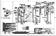
2.3 ELECTRICAL INSTALLATION 2.3.1 TYPICAL WIRING<br />
Since the <strong>R<strong>RTD</strong></strong> can cover a broad range of applications, wiring will be dependent upon the user’s protection and monitoring<br />
scheme. This section covers most of the typical <strong>R<strong>RTD</strong></strong> interconnections.<br />
The terminals have been logically grouped together for explanation purposes. A typical wiring diagram for the <strong>R<strong>RTD</strong></strong> is<br />
shown below. For further information on specific wiring applications, please refer to Chapter 7: APPLICATIONS or contact<br />
<strong>GE</strong> Multilin for further information.<br />
Hazard may result if the product is not used for intended purposes. This equipment can only be serviced by trained<br />
personnel.<br />
WARNING<br />
STATOR<br />
WINDING 1<br />
STATOR<br />
WINDING 2<br />
STATOR<br />
WINDING 3<br />
STATOR<br />
WINDING 4<br />
STATOR<br />
WINDING 5<br />
STATOR<br />
WINDING 6<br />
MOTOR<br />
BEARING 1<br />
MOTOR<br />
BEARING 2<br />
PUMP<br />
BEARING 1<br />
PUMP<br />
BEARING 2<br />
PUMP<br />
CASE<br />
AMBIENT<br />
1<br />
2<br />
3 Com<br />
<strong>RTD</strong>1<br />
4<br />
5<br />
shld.<br />
6<br />
7 Com<br />
<strong>RTD</strong>2<br />
8<br />
9<br />
shld.<br />
10<br />
11 Com<br />
<strong>RTD</strong>3<br />
12<br />
13<br />
shld.<br />
14<br />
15 Com<br />
<strong>RTD</strong>4<br />
16<br />
17<br />
shld.<br />
18<br />
19 Com<br />
<strong>RTD</strong>5<br />
20<br />
21<br />
shld.<br />
22<br />
23 Com<br />
<strong>RTD</strong>6<br />
24<br />
25<br />
shld.<br />
26<br />
27 Com<br />
<strong>RTD</strong>7<br />
28<br />
29<br />
shld.<br />
30<br />
31 Com<br />
<strong>RTD</strong>8<br />
32<br />
33<br />
shld.<br />
34<br />
35 Com<br />
<strong>RTD</strong>9<br />
36<br />
37<br />
shld.<br />
38<br />
39 Com<br />
<strong>RTD</strong>10<br />
40<br />
41<br />
shld.<br />
42<br />
43 Com<br />
<strong>RTD</strong>11<br />
44<br />
45<br />
shld.<br />
46<br />
47 Com<br />
<strong>RTD</strong>12<br />
48 shld.<br />
g<br />
<strong>R<strong>RTD</strong></strong><br />
<strong>Remote</strong> <strong>RTD</strong> <strong>Module</strong><br />
813703A5.CDR<br />
<strong>GE</strong> Power Management<br />
CHANNEL 1 CHANNEL 2 CHANNEL 3<br />
RS485 RS485 RS485<br />
WITH OPTION (F)<br />
FIBER<br />
SHLD SHLD SHLD Tx Rx<br />
71 72 73 74 75 76 77 78 79<br />
Figure 2–2: TYPICAL WIRING<br />
369<br />
Motor Management Relay<br />
<strong>GE</strong> Multilin <strong>R<strong>RTD</strong></strong> <strong>Remote</strong> <strong>RTD</strong> <strong>Module</strong> 2-3<br />
CONTROL<br />
POWER<br />
OUTPUT RELAYS OPTION(IO)<br />
DIGITAL INPUTS OPTION (IO)<br />
OPTION (IO)<br />
FILTER GROUND<br />
LINE +<br />
NEUTRAL -<br />
SAFTY GROUND<br />
TRIP<br />
ALARM<br />
AUX. 1<br />
AUX. 2<br />
INPUT 6<br />
INPUT 5<br />
INPUT 4<br />
INPUT 3<br />
INPUT 2<br />
INPUT 1<br />
ANALOG<br />
OUTPUTS<br />
123<br />
124<br />
125<br />
126<br />
111<br />
112<br />
113<br />
114<br />
115<br />
116<br />
117<br />
118<br />
119<br />
120<br />
121<br />
122<br />
51<br />
52<br />
53<br />
54<br />
55<br />
56<br />
57<br />
58<br />
59<br />
60<br />
61<br />
62<br />
1 80<br />
2 81<br />
3 82<br />
4 83<br />
Com- 84<br />
shld. 85<br />
GROUND<br />
BUS<br />
g<br />
<strong>RTD</strong> HI<br />
ALARM<br />
SELF TEST<br />
ALARM<br />
FIBER<br />
Tx<br />
<strong>RTD</strong> trip<br />
ALARM<br />
Flow<br />
Value<br />
Pressure<br />
Value<br />
Rx<br />
L<br />
N<br />
METER<br />
<strong>GE</strong> Power Management<br />
CONTROL<br />
POWER<br />
380VAC / 125VDC<br />
Hottest<br />
Stator<br />
<strong>RTD</strong>1<br />
<strong>RTD</strong>2<br />
cpm-<br />
Shield<br />
PLC<br />
RS485<br />
+<br />
Shield<br />
SCADA<br />
-<br />
2
2<br />
2.3 ELECTRICAL INSTALLATION 2 INSTALLATION<br />
CAUTION<br />
2.3.2 CONTROL POWER<br />
VERIFY THAT THE CONTROL POWER SUPPLIED TO THE RELAY IS WITHIN THE RAN<strong>GE</strong> COVERED BY<br />
THE ORDERED <strong>R<strong>RTD</strong></strong> RELAY’S CONTROL POWER.<br />
Table 2–2: <strong>R<strong>RTD</strong></strong> POWER SUPPLY RAN<strong>GE</strong>S<br />
<strong>R<strong>RTD</strong></strong> POWER SUPPLY AC RAN<strong>GE</strong> DC RAN<strong>GE</strong><br />
HI 40 to 265 V 50 to 300 V<br />
LO 20 to 48 V 20 to 60 V<br />
The <strong>R<strong>RTD</strong></strong> power supply is a switchmode supply. It can operate with either AC or DC voltage applied to it.<br />
Extensive filtering and transient protection has been incorporated into the <strong>R<strong>RTD</strong></strong> to ensure reliable operation in harsh<br />
industrial environments. Transient energy is removed from the module and conducted to ground via the ground terminal.<br />
This terminal must be connected to the cubicle ground bus using a 10AWG wire or a ground braid. Do not daisy chain<br />
grounds with other devices. Each should have its own connection to the ground bus.<br />
The internal supply is protected via a 3.15 A slo-blo fuse that is accessible for replacement. If it must be replaced ensure<br />
that it is replaced with a fuse of equal size (see Fuse Specifications in Technical Specifications - section 2)<br />
2.3.3 <strong>RTD</strong> INPUTS<br />
The <strong>R<strong>RTD</strong></strong> can monitor up to 12 <strong>RTD</strong> inputs for Stator, Bearing, Ambient, or Other temperature applications. The type of<br />
each <strong>RTD</strong> is field programmable as: 100 Ω Platinum (DIN.43760), 100 Ω Nickel, 120 Ω Nickel, or 10 Ω Copper. <strong>RTD</strong>s must<br />
be the three wire type. There are no provisions for the connection of thermistors.<br />
The <strong>RTD</strong> circuitry compensates for lead resistance, provided that each of the three leads is the same length. Lead resistance<br />
should not exceed 25 Ω per lead for platinum and nickel type <strong>RTD</strong>s or 3 Ω per lead for Copper type <strong>RTD</strong>s.<br />
Shielded cable should be used to prevent noise pickup in industrial environments. <strong>RTD</strong> cables should be kept close to<br />
grounded metal casings and avoid areas of high electromagnetic or radio interference. <strong>RTD</strong> leads should not be run adjacent<br />
to or in the same conduit as high current carrying wires.<br />
The shield connection terminal of the <strong>RTD</strong> is grounded in the <strong>R<strong>RTD</strong></strong> and should not be connected to ground at the motor or<br />
anywhere else to prevent noise pickup from circulating currents.<br />
If 10 Ω Copper <strong>RTD</strong>s are used, special care should be taken to keep the lead resistance as low as possible to maintain<br />
accurate readings.<br />
<strong>RTD</strong> SENSING<br />
<strong>RTD</strong> #1<br />
<strong>R<strong>RTD</strong></strong> RELAY<br />
SAFETY GROUND<br />
Shield<br />
Hot<br />
Return<br />
Compensation<br />
Shield<br />
Com<br />
12<br />
4<br />
1<br />
2<br />
3<br />
MOTOR<br />
STARTER<br />
<strong>RTD</strong><br />
TERMINALS<br />
IN MOTOR<br />
STARTER<br />
Figure 2–3: <strong>RTD</strong> INPUTS<br />
MOTOR<br />
3WIRE SHIELDED CABLE<br />
Route cable in separate conduit from<br />
current carrying conductors<br />
<strong>RTD</strong> TERMINALS<br />
AT MOTOR<br />
Maximum total lead resistance<br />
25 ohms (Platinum &Nickel <strong>RTD</strong>s)<br />
3ohms (Copper <strong>RTD</strong>s)<br />
<strong>RTD</strong> IN<br />
MOTOR<br />
STATOR<br />
OR<br />
BEARING<br />
813704A2.CDR<br />
2-4 <strong>R<strong>RTD</strong></strong> <strong>Remote</strong> <strong>RTD</strong> <strong>Module</strong> <strong>GE</strong> Multilin
2 INSTALLATION 2.3 ELECTRICAL INSTALLATION<br />
CAUTION<br />
2.3.4 DIGITAL INPUTS<br />
DO NOT CONNECT LIVE CIRCUITS TO THE <strong>R<strong>RTD</strong></strong> DIGITAL INPUTS. THEY ARE DESIGNED FOR DRY CON-<br />
TACT CONNECTIONS ONLY.<br />
The <strong>R<strong>RTD</strong></strong> provides 6 programmable digital inputs with the Input/Output option (IO). They can also be programmed for use<br />
as generic inputs to set up trips and alarms or for monitoring purposes based on external contact inputs.<br />
A twisted pair of wires should be used for digital input connections.<br />
2.3.5 ANALOG OUTPUTS<br />
The <strong>R<strong>RTD</strong></strong> provides 4 analog current output channels with the Input/Output option (IO). These outputs are field programmable<br />
to a full-scale range of either 0 to 1 mA (into a maximum 2.4 kΩ impedance) and 4 to 20 or 0 to 20 mA (into a maximum<br />
600 Ω impedance).<br />
As shown in Figure 2–2: TYPICAL WIRING on page 2–3, these outputs share one common return. Polarity of these outputs<br />
must be observed for proper operation.<br />
Shielded cable should be used for connections, with only one end of the shield grounded, to minimize noise effects. The<br />
analog output circuitry is isolated. Transorbs limit this isolation to ±36 V with respect to the <strong>R<strong>RTD</strong></strong> safety ground.<br />
If an analog voltage output is required, a burden resistor must be connected across the input of the SCADA or measuring<br />
device (see the figure below). Ignoring the input impedance of the input,<br />
R LOAD<br />
=<br />
VFULL SCALE<br />
---------------------------------<br />
IMAX For 0 to 1 mA, for example, if 5 V full scale is required to correspond to 1 mA,<br />
R LOAD<br />
VFULL SCALE<br />
---------------------------------<br />
IMAX = = --------------------<br />
5 V<br />
= 5000 Ω<br />
0.001 A<br />
For 4 to 20 mA, this resistor would be<br />
R LOAD<br />
VFULL SCALE<br />
---------------------------------<br />
IMAX = = --------------------<br />
5 V<br />
= 250 Ω<br />
0.020 A<br />
Analog Outputs<br />
1<br />
2<br />
3<br />
4<br />
Com-<br />
Shield<br />
80<br />
81<br />
82<br />
83<br />
84<br />
85<br />
SCADA<br />
OR<br />
PLC<br />
OR<br />
METERING<br />
DEVICE<br />
840714A3.CDR<br />
Figure 2–4: ANALOG OUTPUT VOLTA<strong>GE</strong> CONNECTION<br />
2.3.6 DISPLAY<br />
Monitoring and setting of the <strong>R<strong>RTD</strong></strong> module can be performed via the 369 Motor Management Relay through a communication<br />
link to the <strong>R<strong>RTD</strong></strong>. If a stand alone <strong>R<strong>RTD</strong></strong> is required, a Quick Panel display can be configured to monitor actual values.<br />
The <strong>RTD</strong>PC program is used to program the module when it is configured as a stand alone.<br />
<strong>GE</strong> Multilin <strong>R<strong>RTD</strong></strong> <strong>Remote</strong> <strong>RTD</strong> <strong>Module</strong> 2-5<br />
R<br />
V +<br />
V -<br />
2
2<br />
2.3 ELECTRICAL INSTALLATION 2 INSTALLATION<br />
2.3.7 OUTPUT RELAYS<br />
The <strong>R<strong>RTD</strong></strong> provides four form C output relays. They have been labeled Trip, Aux 1, Aux 2 and Alarm. Each relay has normally<br />
open (NO) and normally closed (NC) contacts and can switch up to 8 A at either 250 V AC or 30 V DC with a resistive<br />
load. The NO or NC state is determined by the ‘no power’ state of the relay outputs.<br />
All four output relays may be programmed for fail-safe or non-fail-safe operation. When in fail-safe mode, output relay activation<br />
or a loss of control power will cause the contacts to go to their power down state.<br />
For example:<br />
• A fail-safe NO contact will close when the <strong>R<strong>RTD</strong></strong> is powered up (if no prior unreset trip conditions) and will open when<br />
activated (tripped) or when the <strong>R<strong>RTD</strong></strong> loses control power.<br />
• A non-fail-safe NO contact will remain open when the <strong>R<strong>RTD</strong></strong> is powered up (unless a prior unreset trip condition) and<br />
will close only when activated (tripped). If control power is lost while the output relay is activated (NO contacts closed)<br />
the NO contacts will open.<br />
Thus, in order to cause a trip on loss of control power to the <strong>R<strong>RTD</strong></strong>, the Trip relay should be programmed as fail-safe. See<br />
Figure 2–2: TYPICAL WIRING for typical wiring of contactors and breakers for fail-safe and non-fail-safe operation.<br />
Output relays will remain latched after activation if the fault condition persists or the protection element has been programmed<br />
as latched. This means that once this relay has been activated it will remain in the active state until the <strong>R<strong>RTD</strong></strong> is<br />
manually reset. The Trip relay cannot be reset if a timed lockout is in effect. Lockout time will be adhered to regardless of<br />
whether control power is present or not.<br />
The relay contacts may be reset if motor conditions allow, by pressing the RESET key, using the REMOTE RESET switch<br />
or via communications. The Emergency Restart feature overrides all features to reset the <strong>R<strong>RTD</strong></strong>.<br />
The rear of the <strong>R<strong>RTD</strong></strong> relay shows output relay contacts in their power down state.<br />
2.3.8 RS485 COMMUNICATIONS<br />
Three independent two-wire RS485 ports are provided. If option (F), the fiber optic port, is installed and used the Comm 3<br />
RS485 port, may not be used. The RS485 ports are isolated as a group.<br />
Up to 32 devices can be daisy-chained together on a single serial communication channel without exceeding the driver<br />
capability. For larger systems, additional serial channels must be added. Commercially available repeaters may also be<br />
used to increase the number of relays on a single channel to a maximum of 254. Note that there may only be one master<br />
device per serial communication link.<br />
Connections should be made using shielded twisted pair cables (typically 24AWG). Suitable cables should have a characteristic<br />
impedance of 120 Ω (e.g. Belden #9841) and total wire length should not exceed 4000 feet. Commercially available<br />
repeaters can be used to extend transmission distances.<br />
Voltage differences between remote ends of the communication link are not uncommon. For this reason, surge protection<br />
devices are internally installed across all RS485 terminals. Internally, an isolated power supply with an optocoupled data<br />
interface is used to prevent noise coupling. The source computer/PLC/SCADA system should have similar transient protection<br />
devices installed, either internally or externally, to ensure maximum reliability.<br />
To ensure that all devices in a daisy-chain are at the same potential, it is imperative that the common terminals<br />
of each RS485 port are tied together and grounded in one location only, at the master. Failure to do so<br />
CAUTION<br />
may result in intermittent or failed communications.<br />
Correct polarity is also essential. <strong>R<strong>RTD</strong></strong>s must be wired with all positive (+) terminals connected together and all negative<br />
(–) terminals connected together. Each relay must be daisy-chained to the next one. Avoid star or stub connected configurations.<br />
The last device at each end of the daisy chain should be terminated with a 120 Ω 1/4 W resistor in series with a 1nF<br />
capacitor across the ‘+’ and ‘–’ terminals. Observing these guidelines will result in a reliable communication system that is<br />
immune to system transients.<br />
2-6 <strong>R<strong>RTD</strong></strong> <strong>Remote</strong> <strong>RTD</strong> <strong>Module</strong> <strong>GE</strong> Multilin
3 <strong>RTD</strong>PC INTERFACE 3.1 INTRODUCTION<br />
3 <strong>RTD</strong>PC INTERFACE 3.1 INTRODUCTION 3.1.1 REQUIREMENTS<br />
The following minimum requirements must be met for the <strong>RTD</strong>PC software to operate properly.<br />
Processor: Minimum 486, Pentium or higher recommended.<br />
Memory: Minimum 4 MB RAM, 16 MB recommended. Minimum 540 K of conventional memory.<br />
Hard Drive: 20 MB free space required before installation of software.<br />
O/S: Minimum Windows 3.1/3.11, Windows NT, or Windows 95/98 (recommended).<br />
Windows 3.1 Users must ensure that SHARE.EXE is installed.<br />
Other: CD-ROM or internet capability to install <strong>RTD</strong>PC<br />
(if neither is available, 3.5" floppy disks can be ordered from the factory)<br />
If <strong>RTD</strong>PC is currently installed, note the path and directory name. This information is required when upgrading.<br />
The <strong>RTD</strong>PC software is included on the <strong>GE</strong> Multilin Products CD included with the <strong>R<strong>RTD</strong></strong>. If your PC does not have CD-<br />
ROM capability, the software may be downloaded from the <strong>GE</strong> Multilin website at www.<strong>GE</strong>industrial.com/multilin or ordered<br />
on 3.5" floppy disks from the nearest <strong>GE</strong> Multilin office.<br />
All products include the <strong>GE</strong> Multilin Products CD. Since this CD is essentially a “snapshot” of the <strong>GE</strong> Multilin website,<br />
the procedures for installation from the CD and the Web are identical. However, the website will always contain<br />
the newest versions and is recommended for upgrading the software.<br />
3.1.2 INSTALLING <strong>RTD</strong>PC<br />
Installation of the <strong>RTD</strong>PC software is accomplished as follows.<br />
1. Ensure that Windows is running and functional on the local PC<br />
2. Insert the <strong>GE</strong> Multilin Products CD into your CD-ROM drive or point your web browser to the <strong>GE</strong> Multilin website at<br />
www.<strong>GE</strong>industrial.com/multilin. With Windows 95/98, the Products CD will launch the welcome screen automatically<br />
(alternately, you may open the index.htm file in the Products CD root directory). Since the Products CD is essentially<br />
a “snapshot” of the <strong>GE</strong> Multilin website, the procedures for installation from the CD and the Web are identical from this<br />
point forward.<br />
3. Click the Index By Product Name item from the main page menu and select the <strong>R<strong>RTD</strong></strong> <strong>Remote</strong> <strong>RTD</strong> <strong>Module</strong> from the<br />
product list to open the <strong>R<strong>RTD</strong></strong> product page.<br />
4. Click the Software menu item from the Product Resources list to proceed to the <strong>R<strong>RTD</strong></strong> software page.<br />
5. The latest version of the <strong>RTD</strong>PC software will be shown. Select the <strong>RTD</strong>PC Program item to download the installation<br />
program to your local PC. Run the installation program and follow the prompts to install the software to the desired<br />
directory. When complete, a new <strong>GE</strong> Multilin group window will appear containing the <strong>RTD</strong>PC icon.<br />
3.1.3 UPGRADING <strong>RTD</strong>PC<br />
The following procedure determines if the currently installed version of <strong>RTD</strong>PC requires upgrading:<br />
1. Run the <strong>RTD</strong>PC software.<br />
2. Select the Help > About <strong>RTD</strong>PC menu item.<br />
3. Compare the version shown in this window with the version on the Products CD or website. If the installed version is<br />
lower than the version on the CD or web, then <strong>RTD</strong>PC needs to be upgraded.<br />
4. To upgrade the <strong>RTD</strong>PC software, follow the installation instructions shown in the previous section. The installation program<br />
will automatically upgrade the <strong>RTD</strong>PC software.<br />
<strong>GE</strong> Multilin <strong>R<strong>RTD</strong></strong> <strong>Remote</strong> <strong>RTD</strong> <strong>Module</strong> 3-1<br />
3
3<br />
3.2 USING <strong>RTD</strong>PC 3 <strong>RTD</strong>PC INTERFACE<br />
3.2 USING <strong>RTD</strong>PC 3.2.1 CONFIGURATION<br />
1. Connect the computer containing the <strong>RTD</strong>PC software to the relay via the Channel 1 or 2 RS485 port. Channel 3 is<br />
designated for communication to the 369 relay for remote <strong>RTD</strong> monitoring and is not meant for use with the <strong>RTD</strong>PC<br />
software.<br />
2. Run the <strong>RTD</strong>PC software. Once the program starts to operate, it will not automatically communicate with the relay<br />
unless enabled to do so (see the Startup Mode option below). The LED status and display message shown will match<br />
actual relay state if communications is established.<br />
3. To setup communications, select Communication > Computer menu item.<br />
4.<br />
Figure 3–1: COMMUNICATION / COMPUTER WINDOW<br />
Set Slave Address to match that programmed into relay.<br />
5. Set Communication Port# to the computer port connected to the relay.<br />
6. Set Baud Rate and Parity to match that programmed into relay.<br />
7. Set Control Type to type used.<br />
8. Set Startup Mode to the desired startup (communicate or file)<br />
9. Select ON to enable communications with new settings.<br />
3.2.2 UPGRADING FIRMWARE<br />
1. To upgrade the relay firmware, connect a computer to the Channel 1 RS485 Port of the <strong>R<strong>RTD</strong></strong>. Channels 2 and 3 cannot<br />
be used to upgrade the relay firmware.<br />
2. Run <strong>RTD</strong>PC and establish communications with the relay.<br />
3. Select the Communication > Upgrade Firmware menu item. The following window will appear:<br />
4. Select Yes to proceed or No to abort. Remember, all previously programmed setpoints will be erased! If you have not<br />
already created a setpoint file, it is highly recommended that the current setpoints be saved to disk by following the<br />
procedure in Section 3.2.3: CREATING A NEW SETPOINT FILE on page 3–3 before continuing with the firmware<br />
upgrade.<br />
5. The Load Firmware window will appear. Locate the firmware file to load into the relay and select OK to proceed or<br />
Cancel to quit the firmware upgrade.<br />
3-2 <strong>R<strong>RTD</strong></strong> <strong>Remote</strong> <strong>RTD</strong> <strong>Module</strong> <strong>GE</strong> Multilin
3 <strong>RTD</strong>PC INTERFACE 3.2 USING <strong>RTD</strong>PC<br />
6. The Upload Firmware dialog box shown below will appear. This provides one last chance to cancel the firmware<br />
upgrade. Select Yes to proceed, No to load a different firmware file, or Cancel to end the firmware upgrade. This will<br />
be the last chance to cancel the firmware upgrade – all previously programmed setpoints will be erased!<br />
7. The <strong>RTD</strong>PC software automatically puts the relay into upload mode and then begin loading the file selected.<br />
8. When loading is complete, the relay will require programming. To reload the previously programmed setpoints, see the<br />
procedure in Section 3.2.5: DOWNLOADING A SETPOINT FILE on page 3–4.<br />
3.2.3 CREATING A NEW SETPOINT FILE<br />
1. To create a new setpoint file, run <strong>RTD</strong>PC. It is not necessary to have an <strong>R<strong>RTD</strong></strong> unit connected to the computer to create<br />
the file; however, some setpoint sections are only active if there is communication with an <strong>R<strong>RTD</strong></strong>. The <strong>RTD</strong>PC status<br />
bar will indicate that the program is in “Editing File” mode and “Not Communicating”.<br />
2. From the Setpoint menu, choose the appropriate setpoints section to program, for example, S3 <strong>RTD</strong> Temperature ><br />
<strong>RTD</strong> Protection to enter output relay setup setpoints.<br />
Figure 3–2: <strong>RTD</strong> PROTECTION WINDOW<br />
3. When you are finished programming a page, select OK to store the information to the <strong>RTD</strong>PC scratchpad memory<br />
(note: this action does not store the information as a file on a disk).<br />
4. Repeat steps 2 to 3 until all the desired setpoints are programmed.<br />
5. Select the File > Save As menu item to store these setpoints to the disk. Enter the location and file name of the setpoint<br />
file with a file extension of ‘.<strong>RTD</strong>’ and select OK.<br />
6. The file is now saved. See Section 3.2.5: DOWNLOADING A SETPOINT FILE on page 3–4 for instructions on reloading<br />
this file to the <strong>R<strong>RTD</strong></strong>.<br />
<strong>GE</strong> Multilin <strong>R<strong>RTD</strong></strong> <strong>Remote</strong> <strong>RTD</strong> <strong>Module</strong> 3-3<br />
3
3<br />
3.2 USING <strong>RTD</strong>PC 3 <strong>RTD</strong>PC INTERFACE<br />
3.2.4 EDITING A SETPOINT FILE<br />
The following procedure describes how to edit setpoint files.<br />
1. Run the <strong>RTD</strong>PC software. It is not necessary to have an <strong>R<strong>RTD</strong></strong> unit connected to the computer. The status bar will indicate<br />
that the program is in “Polling Relay” mode and “Not Communicating”.<br />
2. If the <strong>RTD</strong>PC is communicating, select the Communication > Computer menu item to launch the COMMUNICA-<br />
TION/COMPUTER window (see Figure 3–1: COMMUNICATION / COMPUTER WINDOW on page 3–2) and set Communicate<br />
to "Off". Click OK to turn off communications to the relay and place <strong>RTD</strong>PC in “Editing File” mode.<br />
3. Open a setpoint file by selecting the File > Open menu item. Locate the appropriate <strong>R<strong>RTD</strong></strong> setpoint files (ending with<br />
the extension ’.<strong>RTD</strong>’) and select OK.<br />
4. From the Setpoints menu item, choose the appropriate setpoints section to program; for example, System Setup ><br />
Output Relay Setup to edit the output relay setup setpoints. When you have finished editing a page, select OK to<br />
store the information to the <strong>R<strong>RTD</strong></strong> scratchpad memory (NOTE: this action does not store the information as a file on a<br />
disk).<br />
5. Repeat Step 4 until all the desired setpoints are edited. Select the File > Save As menu item to store this file to disk.<br />
Enter the location and file name of the setpoint file with a file extension of ‘.<strong>RTD</strong>’.<br />
6. The file is now saved to disk. See Section 3.2.5: DOWNLOADING A SETPOINT FILE on page 3–4 for instructions on<br />
downloading this file to the <strong>R<strong>RTD</strong></strong>.<br />
3.2.5 DOWNLOADING A SETPOINT FILE<br />
The following procedure describes how to download setpoint files to the <strong>R<strong>RTD</strong></strong>.<br />
1. To download a pre-programmed setpoint file to the <strong>R<strong>RTD</strong></strong>, run <strong>RTD</strong>PC and establish communications with the connected<br />
relay via the RS485 connector.<br />
2. Select the File > Open menu item to locate the setpoint file to be loaded into the relay. Click OK to load.<br />
3. When the file is completely loaded, the <strong>RTD</strong>PC software will break communications with the connected relay and the<br />
status bar changes to indicate “Editing File”, “Not Communicating”.<br />
4. Select the File > Send Info To Relay menu item to download the setpoint file to the connected relay.<br />
5. When the file is completely downloaded, the status bar will revert back to “Communicating”. The <strong>R<strong>RTD</strong></strong> now contains<br />
all the setpoints as programmed in the setpoint file.<br />
If an attempt is made to download a setpoint file with a revision number that does not match the relay firmware revision,<br />
the following message type will appear:<br />
See Section 3.2.6: UPGRADING SETPOINT FILE TO NEW REVISION on page 3–5 for instructions on upgrading<br />
the setpoint file.<br />
3-4 <strong>R<strong>RTD</strong></strong> <strong>Remote</strong> <strong>RTD</strong> <strong>Module</strong> <strong>GE</strong> Multilin
3 <strong>RTD</strong>PC INTERFACE 3.2 USING <strong>RTD</strong>PC<br />
3.2.6 UPGRADING SETPOINT FILE TO NEW REVISION<br />
The following procedure describes how to upgrade setpoint file revisions. It may be necessary to upgrade the revision code<br />
for a previously saved setpoint file when the <strong>R<strong>RTD</strong></strong> firmware is upgraded.<br />
1. To upgrade the revision of a previously saved setpoint file, run the 369PC software and establish communications with<br />
the <strong>R<strong>RTD</strong></strong> through the RS485 connector.<br />
2. Select the Actual > A5 Relay Information menu item and record the Main Software revision number (for example,<br />
59CMB115.000, where 115 is the main revision identifier and refers to firmware version 1.15).<br />
Figure 3–3: RELAY INFORMATION WINDOW<br />
3. Select the File > Open menu item and select the setpoint file to be downloaded to the connected relay. When the file is<br />
open, the <strong>RTD</strong>PC software will be in “File Editing” mode and “Not Communicating”.<br />
4. Select the File > Properties menu item and note the version code of the setpoint file.<br />
Figure 3–4: SETPOINT FILE PROPERTIES<br />
5. If the Version code (e.g. 1.4X above) differs the firmware revision (noted in step 2 as 115), select the revision code that<br />
matches the firmware from the pull-down tab. For example: for firmware revision 59CMB140.000 and current setpoint<br />
revision as 1.15; change the Version code to 1.4X to upgrade.<br />
6. Select the File > Save menu item to save the setpoint file.<br />
7. To download the upgraded setpoint file to the <strong>R<strong>RTD</strong></strong>, see Section 3.2.5: DOWNLOADING A SETPOINT FILE on page<br />
3–4.<br />
<strong>GE</strong> Multilin <strong>R<strong>RTD</strong></strong> <strong>Remote</strong> <strong>RTD</strong> <strong>Module</strong> 3-5<br />
3
3<br />
3.2 USING <strong>RTD</strong>PC 3 <strong>RTD</strong>PC INTERFACE<br />
This procedure describes how to print a list of the <strong>R<strong>RTD</strong></strong> setpoints and/or actual values.<br />
1. Start <strong>RTD</strong>PC. It is not necessary to establish communications.<br />
2. Select the File > Open menu item to open a previously saved setpoint file, or<br />
establish communications with a connected <strong>R<strong>RTD</strong></strong> unit.<br />
3. Select the File > Print Setup menu item. The following window will appear.<br />
• Select Actual Values to print a list of actual values.<br />
• Select Setpoints (All) or Setpoints (Enabled Features) to print a list of setpoints.<br />
• Select User Definable Memory Map to print the user-definable memory map.<br />
4. Click OK to close the Window.<br />
5. Select the File > Print menu item to send the setpoint/actual values file to the connected printer.<br />
3.2.7 PRINTING<br />
3.2.8 TROUBLESHOOTING<br />
This section provides some tips for troubleshooting <strong>RTD</strong>PC when troubles are encountered within the Windows environment,<br />
e.g. General Protection Fault (GPF), Missing Window, Problems in Opening/Saving Files, and Application<br />
Error.<br />
If the <strong>R<strong>RTD</strong></strong> program causes Windows system errors:<br />
• Ensure the <strong>RTD</strong>PC software is correctly installed and the PC being used meets the minimum requirements.<br />
• Ensure that only one copy of <strong>RTD</strong>PC is running at a given time: the <strong>RTD</strong>PC software cannot multi-task.<br />
3-6 <strong>R<strong>RTD</strong></strong> <strong>Remote</strong> <strong>RTD</strong> <strong>Module</strong> <strong>GE</strong> Multilin
4 SETPOINTS 4.1 S1 SETUP<br />
4 SETPOINTS 4.1 S1 SETUP 4.1.1 SETPOINT ACCESS<br />
The communication access may be changed through the <strong>RTD</strong>PC software. Setpoint access is changed in the Setpoint ><br />
S1 Setup menu item. An access tab is shown only when communicating with a relay. To set a passcode, click the Change<br />
Passcode button. Enter and verify a new passcode; after a passcode is entered, the Setpoint Access changes to "Read<br />
Only". When setpoints are changed through the PC program during Read Only access, the user is prompted to enter the<br />
passcode before the new setpoint is stored. To allow extended write access, click on Allow Write Access and enter the<br />
passcode. To change the access level back to "Read Only", click Restrict Write Access. If 30 minutes elapses without setpoint<br />
changes, or if control power is cycled, access automatically reverts to "Read Only".<br />
If the access level is "Read and Write", write access to setpoints is automatic and a 0 passcode need not be entered. If the<br />
programmed passcode is not known, consult the factory service department with the Encrypted Passcode to be decoded.<br />
4.1.2 PREFERENCES<br />
The Preferences section of the Setpoint > S1 Setup menu item allows the user to set the temperature display units to<br />
either Celsius or Fahrenheit. The value chosen here will be reflected in all temperature actual values. <strong>RTD</strong> setpoints are<br />
programmed in Celsius only.<br />
<strong>GE</strong> Multilin <strong>R<strong>RTD</strong></strong> <strong>Remote</strong> <strong>RTD</strong> <strong>Module</strong> 4-1<br />
4
4<br />
4.1 S1 SETUP 4 SETPOINTS<br />
4.1.3 <strong>R<strong>RTD</strong></strong> COMMUNICATIONS<br />
The <strong>R<strong>RTD</strong></strong> is equipped with three independent RS485 serial ports. The <strong>R<strong>RTD</strong></strong> can act as a stand-alone unit or can be connected<br />
along with a maximum of three (3) other <strong>R<strong>RTD</strong></strong>s to the 369 Motor Management Relay. In this case, Channel 3<br />
must be used for communication between the devices (see Section 6.1.4: MONITORING OF UP TO 60 <strong>RTD</strong>s on<br />
page 6–3 for additional details). Communications Channels 1 and 2 may be used by other devices (for example, computers<br />
or PLCs). Only Channel 1 may be used to upgrade firmware on the <strong>R<strong>RTD</strong></strong>.<br />
The CHANNEL 3 APPLICATION setpoint of the 369 must be set to "<strong>R<strong>RTD</strong></strong>" and each <strong>Remote</strong> <strong>RTD</strong> must have its application<br />
set to "Modbus" and assigned a unique address. Each <strong>R<strong>RTD</strong></strong> slave address must be set prior to connecting it to the<br />
network. Establish communication with only one <strong>R<strong>RTD</strong></strong> by using the default slave address of 254. Then change the Slave<br />
Address in the S1 Setpoints > Setup window. When this new Slave Address is stored, the <strong>R<strong>RTD</strong></strong> will lose communications<br />
with <strong>RTD</strong>PC. At this point, the new address must then be stored in Communications Setup and communications re-established<br />
with the relay.<br />
Option F, a fiber optic port, may be ordered and used for Channel 3 communications. If the Channel 3 fiber optic port is<br />
used, the Channel 3 RS485 connection is disabled.<br />
RS485 communications support a subset of RTU protocol. Each must have a unique address from 1 to 254. Address 0 is<br />
the broadcast address which all relays listen to. Addresses do not have to be sequential but no two devices can have the<br />
same address or conflicts resulting in errors will occur. Generally each added to the link will use the next higher address<br />
starting at 1. A maximum of 32 devices can be daisy chained and connected to a DCS, PLC or PC using the RS485 ports.<br />
A repeater may be used to increase the number of relays on a single link to greater than 32.<br />
4.1.4 REAL TIME CLOCK<br />
The time/date stamp is used to track events for diagnostic purposes. The date and time are preset but may be entered<br />
manually. A battery allows the internal clock to run continuously even when power is off. It has the same accuracy as an<br />
electronic watch, approximately ±1 minute per month. It may be periodically corrected via the clock update command over<br />
the serial link using the PC program.<br />
Enter the current date using two digits for the month, two digits for the day, and four digits for the year. For example, July<br />
15, 2001 would be entered as "07 15 2001". If entered from the keypad, the new date will take effect the moment the [Store<br />
Relay Time and Date] button is clicked. Enter the current time, by using two digits for the hour in 24 hour time, two digits for<br />
the minutes, and two digits for the seconds. If entered from the keypad, the new time will take effect the moment the [Store<br />
Relay Time and Date] button is clicked.<br />
If the serial communication link is used, then all the relays can keep time in synchronization with each other. A new clock<br />
time is pre-loaded into the memory map via the communications port by a remote computer to each relay connected on the<br />
communications channel. The computer broadcasts (address 0) a “set clock” command to all relays. Then all relays in the<br />
system begin timing at the exact same instant. There can be up to 100 ms of delay in receiving serial commands so the<br />
clock time in each relay is ±100 ms, ± the absolute clock accuracy in the PLC or PC (see Chapter 8: COMMUNICATIONS<br />
for information on programming the time and synchronizing commands).<br />
4-2 <strong>R<strong>RTD</strong></strong> <strong>Remote</strong> <strong>RTD</strong> <strong>Module</strong> <strong>GE</strong> Multilin
4 SETPOINTS 4.1 S1 SETUP<br />
4.1.5 CLEAR/PRESET DATA<br />
These commands may be used to clear various historical data. This is useful on new installations or to preset information<br />
on existing installations where new equipment has been installed. The PRESET DIGITAL COUNTER message will only be<br />
seen if one of the digital inputs has been configured as a digital input counter.<br />
4.1.6 OPTIONS<br />
The currently installed <strong>R<strong>RTD</strong></strong> options, order code, and serial number are displayed in this window. If new options are<br />
installed after ordering, select the relevant option ("Input/Output" and/or "Fiber Optic"), enter the passcode, and click the<br />
Update Options Now button to update the <strong>RTD</strong>PC software to recognize them.<br />
<strong>GE</strong> Multilin <strong>R<strong>RTD</strong></strong> <strong>Remote</strong> <strong>RTD</strong> <strong>Module</strong> 4-3<br />
4
4<br />
4.2 S2 SYSTEM SETUP 4 SETPOINTS<br />
4.2 S2 SYSTEM SETUP 4.2.1 DESCRIPTION<br />
These setpoints are critical to the operation of the <strong>R<strong>RTD</strong></strong> protective elements and control features. The output relay setup<br />
and Control Functions are not shown if the IO option is not installed.<br />
4.2.2 MONITORING SETUP<br />
When the Trip Counter is enabled and the alarm pickup level is reached, an alarm will occur. To reset the alarm, the trip<br />
counter must be cleared (see Section 4.1.5: CLEAR/PRESET DATA on page 4–3) or the pickup level increased and a reset<br />
command issued. The trip counter alarm can be used to monitor and alarm when a predefined number of trips occur. This<br />
would then prompt the operator or supervisor to investigate the causes of the trips that have occurred. See Section 5.3.1:<br />
TRIP COUNTERS on page 5–4 for details of the individual trip counters.<br />
4.2.3 OUTPUT RELAY SETUP<br />
A latched relay (caused by a protective elements alarm or trip) may be reset at any time, providing that the condition that<br />
caused operation is no longer present. Unlatched elements automatically reset when the condition has cleared.<br />
These setpoints allow the relay output operation to be fail-safe or non-failsafe. The latchcode however, is defined individually<br />
for each protective element. Failsafe operation causes the output relay to energize in its normal state and de-energize<br />
when activated by a protection element. A failsafe relay also changes state (if not already activated by a protection element)<br />
when control power is removed from the <strong>R<strong>RTD</strong></strong>. Conversely a non-failsafe relay de-energizes in its normal non-activated<br />
state and does not change state when control power is removed (if not already activated by a protection element).<br />
The choice of failsafe or non-failsafe operation is usually determined by the application. In situations where the process is<br />
more critical than the protected equipment, non-failsafe operation is typically programmed. In situations where the equipment<br />
is more critical than the process, failsafe operation is programmed.<br />
4-4 <strong>R<strong>RTD</strong></strong> <strong>Remote</strong> <strong>RTD</strong> <strong>Module</strong> <strong>GE</strong> Multilin
4 SETPOINTS 4.2 S2 SYSTEM SETUP<br />
4.2.4 CONTROL FUNCTIONS<br />
If enabled the motor may be remotely started and stopped via Modbus communications to the <strong>R<strong>RTD</strong></strong>. Refer to Section<br />
8.2.8: FUNCTION CODE 16: PERFORMING COMMANDS on page 8–7 for details on how to send commands. When a<br />
Stop command is sent the Trip relay will activate for 1 second to complete the trip coil circuit for a breaker application or<br />
break the coil circuit for a contactor application. When a Start command is issued the relay assigned for starting control will<br />
activate for 1 second to complete the close coil circuit for a breaker application or complete the coil circuit for a contactor<br />
application.<br />
The Serial Communication Control functions may also be used to reset the unit. Refer to 8.2.3: FUNCTION CODE 05:<br />
EXECUTE OPERATION on page 8–4 for more information.<br />
<strong>GE</strong> Multilin <strong>R<strong>RTD</strong></strong> <strong>Remote</strong> <strong>RTD</strong> <strong>Module</strong> 4-5<br />
4
4<br />
4.3 S3 <strong>RTD</strong> TEMPERATURE 4 SETPOINTS<br />
4.3 S3 <strong>RTD</strong> TEMPERATURE 4.3.1 DESCRIPTION<br />
These setpoints deal with the <strong>RTD</strong> overtemperature elements of the <strong>R<strong>RTD</strong></strong>.<br />
4.3.2 LOCAL <strong>RTD</strong> PROTECTION<br />
• Application: Each individual <strong>RTD</strong> may be assigned an application. A setting of None effectively turns that individual<br />
<strong>RTD</strong> off. Only <strong>RTD</strong>s with the application set to Stator are used for <strong>RTD</strong> biasing of the thermal model.<br />
• Type: Each <strong>RTD</strong> is individually assigned the <strong>RTD</strong> type connected to it. Multiple types may be used with a single <strong>R<strong>RTD</strong></strong>.<br />
• Name: Each <strong>RTD</strong> may be assigned an 8 character (maximum) name. This name is used in alarm and trip messages.<br />
• Alarm/Hi Alarm/Trip: Each <strong>RTD</strong> can be programmed for separate Alarm, Hi Alarm and Trip levels and relays. Trips<br />
are automatically stored as events. Alarms and Hi Alarms are stored as events only if the Record Alarms as Events<br />
setpoint for that <strong>RTD</strong> is set to Yes.<br />
• Trip Voting: This feature has been included for added <strong>RTD</strong> trip reliability in situations where <strong>RTD</strong> malfunction and nuisance<br />
tripping is common. If enabled that <strong>RTD</strong> will only trip if the <strong>RTD</strong> or <strong>RTD</strong>s listed to be voted with are also above<br />
their trip level. For example, if <strong>RTD</strong> 1 is set to vote with All Stator <strong>RTD</strong>s, the <strong>R<strong>RTD</strong></strong> will only trip if <strong>RTD</strong> 1 is above its trip<br />
level and any one of the other stator <strong>RTD</strong>s is also above its own trip level. <strong>RTD</strong> voting is typically only used on Stator<br />
<strong>RTD</strong>s and typically done between adjacent <strong>RTD</strong>s to detect hot spots.<br />
4-6 <strong>R<strong>RTD</strong></strong> <strong>Remote</strong> <strong>RTD</strong> <strong>Module</strong> <strong>GE</strong> Multilin
4 SETPOINTS 4.3 S3 <strong>RTD</strong> TEMPERATURE<br />
Table 4–1: <strong>RTD</strong> RESISTANCE TO TEMPERATURE<br />
TEMPERATURE <strong>RTD</strong> RESISTANCE (IN OHMS)<br />
°C °F 100 Ω Pt<br />
(DIN43760)<br />
120 Ω Ni 100 Ω Ni 10 Ω Cu<br />
–40 –40 84.27 92.76 79.13 7.49<br />
–30 –22 88.22 99.41 84.15 7.88<br />
–20 –4 92.16 106.15 89.23 8.26<br />
–10 14 96.09 113.00 94.58 8.65<br />
0 32 100.00 120.00 100.0 9.04<br />
10 50 103.90 127.17 105.6 9.42<br />
20 68 107.79 134.52 111.2 9.81<br />
30 86 111.67 142.06 117.1 10.19<br />
40 104 115.54 149.79 123.0 10.58<br />
50 122 119.39 157.74 129.1 10.97<br />
60 140 123.24 165.90 135.3 11.35<br />
70 158 127.07 174.25 141.7 11.74<br />
80 176 130.89 182.84 148.3 12.12<br />
90 194 134.70 191.64 154.9 12.51<br />
100 212 138.50 200.64 161.8 12.90<br />
110 230 142.29 209.85 168.8 13.28<br />
120 248 146.06 219.29 176.0 13.67<br />
130 266 149.82 228.96 183.3 14.06<br />
140 284 153.58 238.85 190.9 14.44<br />
150 302 157.32 248.95 198.7 14.83<br />
160 320 161.04 259.30 206.6 15.22<br />
170 338 164.76 269.91 214.8 15.61<br />
180 356 168.47 280.77 223.2 16.00<br />
190 374 172.46 291.96 231.6 16.39<br />
200 392 175.84 303.46 240.0 16.78<br />
4.3.3 OPEN <strong>RTD</strong> ALARM<br />
The <strong>R<strong>RTD</strong></strong> has an Open <strong>RTD</strong> Sensor Alarm. This alarm will look at all <strong>RTD</strong>s that have been assigned an application other<br />
than ‘None’ and determine if an <strong>RTD</strong> connection has been broken. When a broken sensor is detected, the assigned output<br />
relay will operate and the <strong>RTD</strong>PC program will identify the <strong>RTD</strong> that is broken. It is recommended that if this feature is used,<br />
the alarm be programmed as latched so that intermittent <strong>RTD</strong>s are detected and corrective action may be taken.<br />
<strong>GE</strong> Multilin <strong>R<strong>RTD</strong></strong> <strong>Remote</strong> <strong>RTD</strong> <strong>Module</strong> 4-7<br />
4
4<br />
4.3 S3 <strong>RTD</strong> TEMPERATURE 4 SETPOINTS<br />
4.3.4 SHORT/LOW TEMP <strong>RTD</strong> ALARM<br />
The <strong>R<strong>RTD</strong></strong> has an <strong>RTD</strong> Short/Low Temperature alarm. This alarm will look at all <strong>RTD</strong>s that have an application other than<br />
‘None’ and determine if an <strong>RTD</strong> has either a short or a very low temperature (less than –40°C). When a short/low temperature<br />
is detected, the assigned output relay will operate and a message will appear on the display identifying the <strong>RTD</strong> that<br />
caused the alarm. It is recommended that if this feature is used, the alarm be programmed as latched so that intermittent<br />
<strong>RTD</strong>s are detected and corrective action may be taken.<br />
4-8 <strong>R<strong>RTD</strong></strong> <strong>Remote</strong> <strong>RTD</strong> <strong>Module</strong> <strong>GE</strong> Multilin
4 SETPOINTS 4.4 S4 DIGITAL INPUTS<br />
4.4 S4 DIGITAL INPUTS 4.4.1 DIGITAL INPUT FUNCTIONS<br />
Any of the programmable digital inputs may be programmed as a General Switch Input or <strong>Digital</strong> Counter.<br />
<strong>Digital</strong> input alarms and trips (both General or <strong>Digital</strong> Counter) are activated at the local module, the master’s<br />
output relays DO NOT activate.<br />
Only one digital input may be selected as a digital counter at a time. User defined units and counter name may be defined<br />
and these will appear on all counter related actual value and alarm messages. To clear a digital counter alarm, the alarm<br />
level must be increased or the counter must be cleared or preset to a lower value.<br />
<strong>GE</strong> Multilin <strong>R<strong>RTD</strong></strong> <strong>Remote</strong> <strong>RTD</strong> <strong>Module</strong> 4-9<br />
4
4<br />
4.5 S5 ANALOG OUTPUTS 4 SETPOINTS<br />
4.5 S5 ANALOG OUTPUTS 4.5.1 ANALOG OUTPUT PARAMETER SELECTION<br />
Table 4–2: ANALOG OUTPUT PARAMETERS<br />
PARAMETER NAME RAN<strong>GE</strong> /UNITS STEP DEFAULT<br />
MINIMUM MAXIMUM<br />
Hottest Stator <strong>RTD</strong> –40 to +200°C or –40 to +392°F 1 0 200<br />
<strong>RTD</strong> #1 to 12 –40 to +200°C or –40 to +392°F 1 –40 200<br />
The analog outputs are only configurable for the local <strong>RTD</strong>s.<br />
4-10 <strong>R<strong>RTD</strong></strong> <strong>Remote</strong> <strong>RTD</strong> <strong>Module</strong> <strong>GE</strong> Multilin
4 SETPOINTS 4.6 S6 TESTING<br />
4.6 S6 TESTING 4.6.1 FORCE OUTPUT RELAYS<br />
The Force Output Relay feature provides a method of performing checks on all relay contact outputs. The feature can also<br />
be used for control purposes while the equipment is operating. The forced state overrides the normal operation of the relay<br />
output.<br />
The forced state, if enabled (energized or de-energized), will force the selected relay into the programmed state for as long<br />
as the programmed duration. After the programmed duration expires the forced state will return to disabled and relay operation<br />
will return to normal. If the duration is programmed as Static, the forced state will remain in effect until changed or disabled.<br />
If control power to the <strong>R<strong>RTD</strong></strong> is interrupted, any forced relay condition will be removed.<br />
4.6.2 FORCE ANALOG OUTPUTS<br />
The Force Analog Output setpoints may be used during startup or testing to verify that the analog outputs are functioning<br />
correctly. It may also be used when the motor is running to give manual or communication control of an analog output.<br />
Forcing an analog output overrides its normal functionality.<br />
When the Force Analog Outputs Function is enabled, the output will reflect the forced value as a percentage of the range 4<br />
to 20 mA, 0 to 20 mA, or 0 to 1 mA. Selecting Off will place the analog output channels back in service, reflecting the<br />
parameters programmed to each.<br />
<strong>GE</strong> Multilin <strong>R<strong>RTD</strong></strong> <strong>Remote</strong> <strong>RTD</strong> <strong>Module</strong> 4-11<br />
4
4<br />
4.6 S6 TESTING 4 SETPOINTS<br />
4-12 <strong>R<strong>RTD</strong></strong> <strong>Remote</strong> <strong>RTD</strong> <strong>Module</strong> <strong>GE</strong> Multilin
5 ACTUAL VALUES 5.1 A1 STATUS<br />
5 ACTUAL VALUES 5.1 A1 STATUS 5.1.1 LAST TRIP DATA<br />
Immediately prior to a trip, the <strong>R<strong>RTD</strong></strong> records the cause of trip, the date and time and stores this as pre-trip value. This<br />
allows for ease of troubleshooting when a trip occurs. These values are overwritten when the next trip occurs.<br />
The resetting of any latched trip or alarm is done here. All <strong>RTD</strong> trips and alarms are activated at the master only; thus any<br />
latched <strong>RTD</strong> trip or alarm is resettable at the master by clicking on the Reset button. On the other hand, digital trips or<br />
alarms are activated at the slave only; thus any latched digital trip or alarm is resettable by clicking on the related <strong>R<strong>RTD</strong></strong><br />
reset button.<br />
5.1.2 ALARM STATUS<br />
Any active alarm may be viewed here. If the Line Up and Down keys are not pressed, the active messages will automatically<br />
cycle. The current level causing the alarm is displayed along with the alarm name.<br />
<strong>GE</strong> Multilin <strong>R<strong>RTD</strong></strong> <strong>Remote</strong> <strong>RTD</strong> <strong>Module</strong> 5-1<br />
5
5<br />
5.1 A1 STATUS 5 ACTUAL VALUES<br />
The present state of the digital inputs will be displayed here.<br />
5.1.3 DIGITAL INPUT STATUS<br />
5.1.4 OUTPUT RELAY STATUS<br />
The present state of the output relays will be displayed here. Energized indicates that the NO contacts are now closed and<br />
the NC contacts are now open. De-energized indicates that the NO contacts are now open and the NC contacts are now<br />
closed. Forced indicates that the output relay has been commanded into a certain state.<br />
The date and time from the <strong>R<strong>RTD</strong></strong> real time clock may be viewed here.<br />
5.1.5 REAL TIME CLOCK<br />
5-2 <strong>R<strong>RTD</strong></strong> <strong>Remote</strong> <strong>RTD</strong> <strong>Module</strong> <strong>GE</strong> Multilin
5 ACTUAL VALUES 5.2 A2 TEMPERATURE DATA<br />
5.2 A2 TEMPERATURE DATA 5.2.1 LOCAL <strong>RTD</strong><br />
• LOCAL <strong>RTD</strong>: The temperature level of all 12 internal <strong>RTD</strong>s will be displayed here. The programmed name of each<br />
<strong>RTD</strong> (if changed from the default) will appear as the first line of each message.<br />
5.2.2 LOCAL <strong>RTD</strong> MAXIMUMS<br />
• LOCAL <strong>RTD</strong> MAXIMUMS: The maximum temperature level of all 12 internal <strong>RTD</strong>s will be displayed. The programmed<br />
name of each <strong>RTD</strong> (if changed from the default) will appear as the first line of each message.<br />
<strong>GE</strong> Multilin <strong>R<strong>RTD</strong></strong> <strong>Remote</strong> <strong>RTD</strong> <strong>Module</strong> 5-3<br />
5
5<br />
5.3 A3 STATISTICAL DATA 5 ACTUAL VALUES<br />
5.3 A3 STATISTICAL DATA 5.3.1 TRIP COUNTERS<br />
A breakdown of the number of trips by type is displayed here. When the total reaches 50000, the counter resets to 0 on the<br />
next trip and continues counting. This information can be cleared in the Setpoints > S1 Setup menu item (see Clear/Preset<br />
tab). The date the counters are cleared is recorded.<br />
5.3.2 STATISTICS<br />
The digital counter is displayed when one of the digital inputs is set as a digital counter. The digital counter can be cleared<br />
in the Setpoints > S1 Setup menu item (see Clear/Presets tab). When the digital counter reaches 65535, it is automatically<br />
reset to 0.<br />
5-4 <strong>R<strong>RTD</strong></strong> <strong>Remote</strong> <strong>RTD</strong> <strong>Module</strong> <strong>GE</strong> Multilin
5 ACTUAL VALUES 5.4 A4 EVENT RECORDER<br />
5.4 A4 EVENT RECORDER 5.4.1 EVENT RECORDER<br />
The event recorder stores system information each time an event occurs (for example, a motor trip). A maximum of 40<br />
events are stored, with Event 1 representing the oldest event. When the number of events exceeds 40, Event 1 is deleted<br />
from the event recorder.<br />
Details of selected events can be viewed by clicking the View Data button. Select events by clicking the checkboxes in the<br />
Select column. This data can be stored and/or printed for future reference.<br />
<strong>GE</strong> Multilin <strong>R<strong>RTD</strong></strong> <strong>Remote</strong> <strong>RTD</strong> <strong>Module</strong> 5-5<br />
5
5<br />
5.5 RELAY INFORMATION AND COMMMANDS 5 ACTUAL VALUES<br />
5.5 RELAY INFORMATION AND COMMMANDS 5.5.1 A5 RELAY INFORMATION<br />
<strong>R<strong>RTD</strong></strong> model and manufacture information may be viewed here. The last calibration date is the date the relay was last calibrated<br />
at <strong>GE</strong> Multilin. This information reflects the revisions of the software currently running in the <strong>R<strong>RTD</strong></strong>. This information<br />
should be noted and recorded before calling for technical support or service.<br />
5.5.2 COMMANDS<br />
<strong>R<strong>RTD</strong></strong> commands are performed through the Commands menu, allowing for the refreshing and resetting of local <strong>R<strong>RTD</strong></strong>s.<br />
a) RESET <strong>R<strong>RTD</strong></strong><br />
Each individual <strong>R<strong>RTD</strong></strong> can be reset through the commands menu. This is used to reset <strong>R<strong>RTD</strong></strong> units that have the IO option<br />
and have a latched trip or alarm active.<br />
b) REFRESH <strong>R<strong>RTD</strong></strong><br />
The refresh command sends the setpoints that are saved in the master <strong>R<strong>RTD</strong></strong> to the slave. This command is used when<br />
replacing a <strong>R<strong>RTD</strong></strong> unit.<br />
5-6 <strong>R<strong>RTD</strong></strong> <strong>Remote</strong> <strong>RTD</strong> <strong>Module</strong> <strong>GE</strong> Multilin
6 APPLICATIONS 6.1 <strong>RTD</strong> CIRCUITRY<br />
6 APPLICATIONS 6.1 <strong>RTD</strong> CIRCUITRY 6.1.1 <strong>RTD</strong> CIRCUIT OPERATION<br />
The following is an explanation of how the <strong>RTD</strong> circuitry works in the <strong>R<strong>RTD</strong></strong>.<br />
Figure 6–1: <strong>RTD</strong> CIRCUITRY<br />
A constant current source sends 3 mA DC down legs A and C. A 6 mA DC current returns down leg B. It may be seen that:<br />
or<br />
The above holds true providing that all three leads are the same length, gauge, and material, hence the same resistance.<br />
or<br />
A<br />
B<br />
COMPENSATION<br />
Electronically, subtracting V AB from V BC leaves only the voltage across the <strong>RTD</strong>. In this manner lead length is effectively<br />
negated:<br />
An example of how to add lead compensation to a two wire <strong>RTD</strong> is shown below.<br />
C<br />
3 mA<br />
6 mA<br />
3 mA<br />
RETURN<br />
6.1.2 TWO WIRE <strong>RTD</strong> LEAD COMPENSATION<br />
Figure 6–2: 2 WIRE <strong>RTD</strong> LEAD COMPENSATION<br />
The compensation lead would be added and it would compensate for the Hot and the Return assuming they are all of equal<br />
length and gauge. To compensate for resistance of the Hot and Compensation leads, a resistor equal to the resistance of<br />
the Hot lead could be added to the compensation lead, though in many cases this is unnecessary.<br />
<strong>GE</strong> Multilin <strong>R<strong>RTD</strong></strong> <strong>Remote</strong> <strong>RTD</strong> <strong>Module</strong> 6-1<br />
HOT<br />
840733A1.CDR<br />
VAB = VLeadA + VLeadB and VCB = VLeadC + V<strong>RTD</strong> + VLeadB VAB = Vcomp + Vreturn and VCB = Vhot + V<strong>RTD</strong> + Vreturn RLeadA = RLeadB = RLeadC = RLead Rcomp = Rreturn = Rhot = RLead VCB – VAB = ( VLead + V<strong>RTD</strong> + VLead) – ( VLead + VLead) VCB – VAB = V<strong>RTD</strong> <strong>R<strong>RTD</strong></strong><br />
<strong>RTD</strong> #6<br />
24<br />
23<br />
22<br />
21<br />
COMPENSATION<br />
RESISTOR<br />
COMPENSATION<br />
RETURN<br />
HOT<br />
TERMINAL<br />
<strong>RTD</strong><br />
RETURN<br />
HOT<br />
MOTOR<br />
813711A1.CDR<br />
6
6<br />
6.1 <strong>RTD</strong> CIRCUITRY 6 APPLICATIONS<br />
6.1.3 REDUCED <strong>RTD</strong> LEAD NUMBER APPLICATION<br />
The <strong>R<strong>RTD</strong></strong> requires three leads to be brought back from each <strong>RTD</strong>: Hot, Return, and Compensation. In certain situations<br />
this can be quite expensive. However, it is possible to reduce the number of leads so that three are required for the first<br />
<strong>RTD</strong> and only one for each successive <strong>RTD</strong>. Refer to the following diagram for wiring configuration.<br />
<strong>RTD</strong> #1<br />
<strong>RTD</strong> #2<br />
<strong>RTD</strong> #3<br />
<strong>RTD</strong> #4<br />
<strong>RTD</strong> #5<br />
<strong>RTD</strong> #6<br />
<strong>R<strong>RTD</strong></strong><br />
HOT<br />
RETURN<br />
COMPENSATION<br />
HOT<br />
RETURN<br />
COMPENSATION<br />
HOT<br />
RETURN<br />
COMPENSATION<br />
HOT<br />
RETURN<br />
COMPENSATION<br />
HOT<br />
RETURN<br />
COMPENSATION<br />
HOT<br />
RETURN<br />
COMPENSATION<br />
SHIELD<br />
1<br />
2<br />
3<br />
5<br />
6<br />
7<br />
9<br />
10<br />
11<br />
13<br />
14<br />
15<br />
17<br />
18<br />
19<br />
21<br />
22<br />
23<br />
24<br />
SHIELD<br />
MOTOR<br />
Figure 6–3: REDUCED WIRING <strong>RTD</strong>s<br />
The Hot line is run as usual for each <strong>RTD</strong>. However, the Compensation and Return leads need only be run for the first <strong>RTD</strong>.<br />
At the motor <strong>RTD</strong> terminal box, connect the <strong>RTD</strong> Return leads together with as short as possible jumpers. At the <strong>R<strong>RTD</strong></strong><br />
unit, the Compensation leads must be jumpered together.<br />
Note that an error is produced on each <strong>RTD</strong> equal to the voltage drop across the <strong>RTD</strong> return jumper. This error increases<br />
for each successive <strong>RTD</strong> added as:<br />
V<strong>RTD</strong>1 = V<strong>RTD</strong>1 V<strong>RTD</strong>2 = V<strong>RTD</strong>2 + VJ3 V<strong>RTD</strong>3 = V<strong>RTD</strong>3 + VJ3 + VJ4 V<strong>RTD</strong>4 = V<strong>RTD</strong>4 + VJ3 + VJ4 + VJ5 , etc....<br />
This error is directly dependent on the length and gauge of the jumper wires and any error introduced by a poor connection.<br />
For <strong>RTD</strong> types other than 10C, the error introduced by the jumpers is negligible.<br />
Although this <strong>RTD</strong> wiring technique reduces the cost of wiring, the following disadvantages must be noted:<br />
1. There is an error in temperature readings due to lead and connection resistances. Not recommended for 10C <strong>RTD</strong>s.<br />
2. If the <strong>RTD</strong> Return lead to the <strong>R<strong>RTD</strong></strong> or one of the jumpers breaks, all <strong>RTD</strong>s from the point of the break onwards will<br />
read open.<br />
3. If the Compensation lead breaks or one of the jumpers breaks, all <strong>RTD</strong>s from the point of the break onwards will function<br />
without any lead compensation.<br />
<strong>RTD</strong> #1<br />
<strong>RTD</strong> #2<br />
<strong>RTD</strong> #3<br />
<strong>RTD</strong> #4<br />
<strong>RTD</strong> #5<br />
<strong>RTD</strong> #6<br />
813710A1.CDR<br />
6-2 <strong>R<strong>RTD</strong></strong> <strong>Remote</strong> <strong>RTD</strong> <strong>Module</strong> <strong>GE</strong> Multilin
6 APPLICATIONS 6.1 <strong>RTD</strong> CIRCUITRY<br />
6.1.4 MONITORING OF UP TO 60 <strong>RTD</strong>s<br />
A maximum of four (4) <strong>R<strong>RTD</strong></strong> modules with a 369 can be daisy-chained together as illustrated in Figure 6–5: DAISY<br />
CHAINING <strong>R<strong>RTD</strong></strong> MODULES on page 6–4. This provides the capability of monitoring up to 60 <strong>RTD</strong>s.<br />
The 369 Motor Management Relay is designated as the master and the other <strong>R<strong>RTD</strong></strong>s as the slaves. Each of the <strong>R<strong>RTD</strong></strong><br />
slave modules must be programmed with a unique SLAVE ADDRESS before they can be daisy-chained together. Programming<br />
is accomplished via <strong>RTD</strong>PC by connecting to either the Channel 1 or Channel 1 RS485 port. When all devices connected<br />
to the 369 are communicating properly, the 369PC software can also be used to program individual <strong>R<strong>RTD</strong></strong> modules.<br />
Figure 6–4: <strong>RTD</strong>PC SCREEN<br />
Since the <strong>R<strong>RTD</strong></strong> does not have a display, a HMI, such as the Quick Panel Jr., can be connected to one of the communication<br />
ports. The HMI can be configured to display the information of choice. Visit the <strong>GE</strong> Multilin Web site to obtain a Quick<br />
Panel configuration template.<br />
Please note that <strong>R<strong>RTD</strong></strong> can be connected to only one 369 at a time.<br />
<strong>GE</strong> Multilin <strong>R<strong>RTD</strong></strong> <strong>Remote</strong> <strong>RTD</strong> <strong>Module</strong> 6-3<br />
6
6<br />
6.1 <strong>RTD</strong> CIRCUITRY 6 APPLICATIONS<br />
SLAVE SLAVE SLAVE<br />
SLAVE<br />
MASTER<br />
<strong>GE</strong> Power Management<br />
g<br />
<strong>GE</strong> Power Management<br />
g<br />
<strong>GE</strong> Power Management<br />
g<br />
<strong>GE</strong> Power Management<br />
g<br />
<strong>GE</strong> Power Management<br />
g<br />
<strong>R<strong>RTD</strong></strong><br />
REMOTE <strong>RTD</strong><br />
<strong>Module</strong># 4<br />
<strong>R<strong>RTD</strong></strong><br />
REMOTE <strong>RTD</strong><br />
<strong>Module</strong># 3<br />
<strong>R<strong>RTD</strong></strong><br />
REMOTE <strong>RTD</strong><br />
<strong>Module</strong># 2<br />
<strong>R<strong>RTD</strong></strong><br />
REMOTE <strong>RTD</strong><br />
<strong>Module</strong># 1<br />
369<br />
MOTOR MANA<strong>GE</strong>MENT<br />
RELAY<br />
CHANNEL 1 CHANNEL 2 CHANNEL 3 CHANNEL 1 CHANNEL 2 CHANNEL 3 CHANNEL 1 CHANNEL 2 CHANNEL 3 CHANNEL 1 CHANNEL 2<br />
CHANNEL 3<br />
RS485 RS485 RS485 FIBER RS485 RS485 RS485 FIBER RS485 RS485 RS485 FIBER RS485 RS485 RS485 FIBER<br />
SHLD SHLD SHLD<br />
Tx Rx<br />
SHLD SHLD SHLD<br />
Tx Rx<br />
SHLD SHLD SHLD<br />
Tx Rx<br />
SHLD<br />
SHLD<br />
SHLD<br />
Tx Rx<br />
71 72 73 74 75 76 77 78 79<br />
71 72 73 74 75 76 77 78 79<br />
71 72 73 74 75 76 77 78 79<br />
71 72 73 74 75 76 77 78 79<br />
CHANNEL 1 CHANNEL 2 CHANNEL 3<br />
COMPUTER<br />
or<br />
PLC<br />
RS485 RS485 RS485 FIBER<br />
SHLD SHLD SHLD<br />
Tx Rx<br />
71 72 73 74 75 76 77 78 79<br />
Figure 6–5: DAISY CHAINING <strong>R<strong>RTD</strong></strong> MODULES<br />
6-4 <strong>R<strong>RTD</strong></strong> <strong>Remote</strong> <strong>RTD</strong> <strong>Module</strong> <strong>GE</strong> Multilin<br />
F485<br />
SLAVE SLAVE SLAVE<br />
SLAVE<br />
MASTER<br />
<strong>GE</strong> Power Management<br />
g<br />
<strong>GE</strong> Power Management<br />
g<br />
<strong>GE</strong> Power Management<br />
g<br />
<strong>GE</strong> Power Management<br />
g<br />
<strong>GE</strong> Power Management<br />
g<br />
<strong>R<strong>RTD</strong></strong><br />
REMOTE <strong>RTD</strong><br />
<strong>Module</strong># 4<br />
<strong>R<strong>RTD</strong></strong><br />
REMOTE <strong>RTD</strong><br />
<strong>Module</strong># 3<br />
<strong>R<strong>RTD</strong></strong><br />
REMOTE <strong>RTD</strong><br />
<strong>Module</strong># 2<br />
<strong>R<strong>RTD</strong></strong><br />
REMOTE <strong>RTD</strong><br />
<strong>Module</strong># 1<br />
369<br />
MOTOR MANA<strong>GE</strong>MENT<br />
RELAY<br />
CHANNEL 1 CHANNEL 2 CHANNEL 3<br />
CHANNEL 1 CHANNEL 2 CHANNEL 3 CHANNEL 1 CHANNEL 2 CHANNEL 3 CHANNEL 1 CHANNEL 2 CHANNEL 3 CHANNEL 1 CHANNEL 2<br />
CHANNEL 3<br />
RS485 RS485 RS485 FIBER<br />
RS485 RS485 RS485 FIBER RS485 RS485 RS485 FIBER RS485 RS485 RS485 FIBER RS485 RS485 RS485 FIBER<br />
SHLD SHLD SHLD<br />
Tx Rx<br />
SHLD SHLD SHLD<br />
Tx Rx<br />
SHLD SHLD SHLD<br />
Tx Rx<br />
SHLD SHLD SHLD<br />
Tx Rx<br />
SHLD<br />
SHLD<br />
SHLD<br />
Tx Rx<br />
71 72 73 74 75 76 77 78 79<br />
71 72 73 74 75 76 77 78 79<br />
71 72 73 74 75 76 77 78 79<br />
71 72 73 74 75 76 77 78 79<br />
71 72 73 74 75 76 77 78 79<br />
COMPUTER<br />
or<br />
PLC<br />
QUICK PANEL Jr.<br />
813708A3.CDR<br />
HMI
6 APPLICATIONS 6.2 USING THE <strong>R<strong>RTD</strong></strong> WITH THE 469 RELAY<br />
6.2 USING THE <strong>R<strong>RTD</strong></strong> WITH THE 469 RELAY 6.2.1 INTRODUCTION<br />
Using the <strong>R<strong>RTD</strong></strong> with the 469 eliminates the necessity of wiring <strong>RTD</strong>s back to the 469 for monitoring and/or control functions.<br />
Any <strong>R<strong>RTD</strong></strong>s used with the 469 MUST have the IO option.<br />
The following three scenarios are addressed in this section: control via the 469, monitoring via the 469, and monitoring and<br />
control via the 469. Although only three specific scenarios are described, it is possible to use combinations of them. It is up<br />
to the customer's discretion to apply them according to their needs.<br />
6.2.2 CONTROL VIA THE 469<br />
Use this setup if the application requires the 469 to control <strong>RTD</strong> trips and no monitoring by the 469 is required.<br />
1. Wire the <strong>RTD</strong>s to the <strong>R<strong>RTD</strong></strong> and program the <strong>R<strong>RTD</strong></strong> with trip and alarm levels as described in the <strong>R<strong>RTD</strong></strong> instruction<br />
manual. Program all <strong>R<strong>RTD</strong></strong> trips and alarms as unlatched.<br />
2. Wire trip and alarm output relays from the <strong>R<strong>RTD</strong></strong> to the 469 digital input(s). Program the 469 digital input(s) (one or<br />
more of the General Switch A-D) and assign the appropriate output relay. The General Switch inputs can be renamed<br />
to indicate that it is an <strong>R<strong>RTD</strong></strong> trip or alarm (i.e. <strong>R<strong>RTD</strong></strong> Trip).<br />
3. A trip or alarm from the <strong>R<strong>RTD</strong></strong> will now cause the 469 to issue the trip or alarm to the control scheme. The output relay<br />
of the <strong>R<strong>RTD</strong></strong> will reset as soon as the condition is cleared. The 469 output relay will reset according to whether it is programmed<br />
as latched or unlatched.<br />
4. If monitoring of the <strong>RTD</strong> temperatures is required, the data can be read from the <strong>R<strong>RTD</strong></strong> through communications.<br />
6.2.3 MONITORING VIA THE 469<br />
Use this setup if the application requires the <strong>R<strong>RTD</strong></strong> to control tripping and/or alarms and it is desirable to have the 469 monitor<br />
<strong>RTD</strong> temperatures.<br />
1. Wire the <strong>RTD</strong>s to the <strong>R<strong>RTD</strong></strong> as described in the <strong>R<strong>RTD</strong></strong> instruction manual. If tripping and/or alarms are required, program<br />
the <strong>R<strong>RTD</strong></strong> accordingly and wire the <strong>R<strong>RTD</strong></strong> output relays into the control scheme.<br />
2. The <strong>R<strong>RTD</strong></strong> has 4 Analog Outputs that can be wired to the 469 Analog Inputs. They can be programmed to represent<br />
individual <strong>RTD</strong>s or the Hottest Stator <strong>RTD</strong>.<br />
3. Program the 469 Analog Input Name with the appropriate <strong>RTD</strong> name (e.g. "<strong>Remote</strong> <strong>RTD</strong>1"). Rename the 469 Analog<br />
Input Units (e.g. Deg C). Program the input range and minimum/maximum levels to match the <strong>R<strong>RTD</strong></strong> settings.<br />
4. The <strong>RTD</strong> temperatures can now be monitored by the 469 Analog Input metering data.<br />
5. The <strong>RTD</strong> temperatures can also be obtained from the 469 through communications (by reading the appropriate Analog<br />
Input metering memory map addresses) or by programming the 469 analog outputs appropriately.<br />
6.2.4 MONITORING AND CONTROL VIA THE 469<br />
This setup is to be used if the application requires the 469 to both monitor <strong>RTD</strong> temperatures and control tripping and/or<br />
alarming. This setup provides the most benefit from using the <strong>R<strong>RTD</strong></strong> with the 469.<br />
1. Wire <strong>RTD</strong>s to the <strong>R<strong>RTD</strong></strong> as described in the <strong>R<strong>RTD</strong></strong> instruction manual. DO NOT wire <strong>R<strong>RTD</strong></strong> output relays into the control<br />
scheme and DO NOT program any trips or alarms in the <strong>R<strong>RTD</strong></strong>.<br />
2. Wire the required number of <strong>R<strong>RTD</strong></strong> Analog Outputs to the 469 Analog Inputs. They can be programmed to represent<br />
individual <strong>RTD</strong>s or the Hottest Stator <strong>RTD</strong>.<br />
3. Program the 469 Analog Input Name with the appropriate <strong>RTD</strong> name (e.g. "<strong>Remote</strong> <strong>RTD</strong>1"). Rename the 469 Analog<br />
Input Units (e.g. Deg C). Program the input range and minimum/maximum levels to match the <strong>R<strong>RTD</strong></strong> settings.<br />
4. Program the 469 Analog Inputs with the appropriate trip and/or alarm levels.<br />
<strong>GE</strong> Multilin <strong>R<strong>RTD</strong></strong> <strong>Remote</strong> <strong>RTD</strong> <strong>Module</strong> 6-5<br />
6
6<br />
6.2 USING THE <strong>R<strong>RTD</strong></strong> WITH THE 469 RELAY 6 APPLICATIONS<br />
5. The <strong>RTD</strong> temperatures can now be monitored through the 469 Analog Input metering data. The temperatures can also<br />
be obtained from the 469 through communications (by reading the appropriate Analog Input metering memory map<br />
addresses) or by programming the 469 analog outputs appropriately.<br />
6. The 469 will now control trips and/or alarms for remote <strong>RTD</strong>s. See the wiring diagram below for details.<br />
Figure 6–6: <strong>R<strong>RTD</strong></strong>/469 WIRING DIAGRAM<br />
6-6 <strong>R<strong>RTD</strong></strong> <strong>Remote</strong> <strong>RTD</strong> <strong>Module</strong> <strong>GE</strong> Multilin
7 TESTING 7.1 TEST SETUP<br />
7 TESTING 7.1 TEST SETUP 7.1.1 INTRODUCTION<br />
This chapter demonstrates the procedures necessary to perform a complete functional test of all the <strong>R<strong>RTD</strong></strong> hardware while<br />
also testing firmware/hardware interaction in the process. Testing of the relay during commissioning wiring is correct and<br />
complete.<br />
500 ohm<br />
1<br />
2<br />
3 Com<br />
<strong>RTD</strong>1<br />
4<br />
5<br />
shld.<br />
6<br />
7 Com<br />
<strong>RTD</strong>2<br />
8<br />
9<br />
shld.<br />
10<br />
11 Com<br />
<strong>RTD</strong>3<br />
12<br />
13<br />
shld.<br />
14<br />
15 Com<br />
<strong>RTD</strong>4<br />
16<br />
17<br />
shld.<br />
18<br />
19 Com<br />
<strong>RTD</strong>5<br />
20<br />
21<br />
shld.<br />
22<br />
23 Com<br />
<strong>RTD</strong>6<br />
24<br />
25<br />
shld.<br />
26<br />
27 Com<br />
<strong>RTD</strong>7<br />
28<br />
29<br />
shld.<br />
30<br />
31 Com<br />
<strong>RTD</strong>8<br />
32<br />
33<br />
shld.<br />
34<br />
35 Com<br />
<strong>RTD</strong>9<br />
36<br />
37<br />
shld.<br />
38<br />
39 Com<br />
<strong>RTD</strong>10<br />
40<br />
41<br />
shld.<br />
42<br />
43 Com<br />
<strong>RTD</strong>11<br />
44<br />
45<br />
shld.<br />
46<br />
47 Com<br />
<strong>RTD</strong>12<br />
48 shld.<br />
g <strong>GE</strong><br />
Power Management<br />
<strong>R<strong>RTD</strong></strong><br />
CHANNEL 1 CHANNEL 2 CHANNEL 3<br />
RS485 RS485 RS485<br />
OPTION (F)<br />
FIBER<br />
SHLD SHLD SHLD Tx Rx<br />
71 72 73 74 75 76 77 78 79<br />
1 80<br />
2 81<br />
3 82<br />
4 83<br />
Com- 84<br />
shld. 85<br />
Figure 7–1: SECONDARY INJECTION TEST SETUP<br />
GROUND<br />
BUS<br />
7.1.2 TEST SETUP<br />
813709A4.CDR<br />
<strong>GE</strong> Multilin <strong>R<strong>RTD</strong></strong> <strong>Remote</strong> <strong>RTD</strong> <strong>Module</strong> 7-1<br />
CONTROL<br />
POWER<br />
OUTPUT RELAYS OPTION (IO)<br />
DIGITAL INPUTS OPTION (IO)<br />
OPTION<br />
(IO)<br />
FILTER GROUND<br />
LINE +<br />
NEUTRAL -<br />
SAFTY GROUND<br />
TRIP<br />
ALARM<br />
AUX. 1<br />
AUX. 2<br />
INPUT 6<br />
INPUT 5<br />
INPUT 4<br />
INPUT 3<br />
INPUT 2<br />
INPUT 1<br />
ANALOG<br />
OUTPUTS<br />
F485<br />
123<br />
124<br />
125<br />
126<br />
111<br />
112<br />
113<br />
114<br />
115<br />
116<br />
117<br />
118<br />
119<br />
120<br />
121<br />
122<br />
51<br />
52<br />
53<br />
54<br />
55<br />
56<br />
57<br />
58<br />
59<br />
60<br />
61<br />
62<br />
RS232<br />
R<br />
R<br />
R<br />
A<br />
A<br />
PC<br />
G<br />
G<br />
G<br />
G<br />
A<br />
A<br />
L<br />
N<br />
+<br />
-<br />
<strong>RTD</strong> PC<br />
PROGRAM<br />
7
7<br />
7.2 HARDWARE FUNCTIONAL TESTING 7 TESTING<br />
7.2 HARDWARE FUNCTIONAL TESTING 7.2.1 <strong>RTD</strong> ACCURACY TEST<br />
The <strong>R<strong>RTD</strong></strong> specification for <strong>RTD</strong> input accuracy is ±2°C. Perform the steps below to verify accuracy.<br />
1. Select an <strong>RTD</strong> type of 100 Platinum for all of the 12 <strong>RTD</strong>s.<br />
2. Measured values should be ±2°C or ±4°F. Alter the resistances applied to the <strong>RTD</strong> inputs as per the table below to<br />
simulate <strong>RTD</strong>s and verify accuracy of the measured values. View the measured values in:<br />
A2 TEMPERATURE DATA \ LOCAL <strong>RTD</strong><br />
3. Select the preferred temperature units for the display. Alter the following setpoint:<br />
S1 SETUP \ PREFERENCES \ TEMPERATURE DISPLAY: "Celsius" ( or "Fahrenheit" if preferred)<br />
4. Repeat the above measurements for the other <strong>RTD</strong> types (120 Ω Nickel, 100 Ω Nickel and 10 Ω Copper).<br />
APPLIED<br />
RESISTANCE<br />
100 Ω<br />
PLATINUM<br />
EXPECTED <strong>RTD</strong> TEMPERATURE<br />
READING<br />
MEASURED <strong>RTD</strong> TEMPERATURE<br />
� SELECT ONE: ____(°C) ____(°F)<br />
CELSIUS FAHRENHEIT 1 2 3 4 5 6 7 8 9 10 11 12<br />
80.31 Ω –50°C –58°F<br />
100.00 Ω 0°C 32°F<br />
119.39 Ω 50°C 122°F<br />
138.50 Ω 100°C 212°F<br />
157.32 Ω 150°C 302°F<br />
175.84 Ω 200°C 392°F<br />
APPLIED<br />
RESISTANCE<br />
120 Ω NICKEL<br />
EXPECTED <strong>RTD</strong> TEMPERATURE<br />
READING<br />
MEASURED <strong>RTD</strong> TEMPERATURE<br />
� SELECT ONE: ____(°C) ____(°F)<br />
CELSIUS FAHRENHEIT 1 2 3 4 5 6 7 8 9 10 11 12<br />
86.17 Ω –50°C –58°F<br />
120.00 Ω 0°C 32°F<br />
157.74 Ω 50°C 122°F<br />
200.64 Ω 100°C 212°F<br />
248.95 Ω 150°C 302°F<br />
303.46 Ω 200°C 392°F<br />
APPLIED<br />
RESISTANCE<br />
100 Ω NICKEL<br />
EXPECTED <strong>RTD</strong> TEMPERATURE<br />
READING<br />
MEASURED <strong>RTD</strong> TEMPERATURE<br />
� SELECT ONE: ____(°C) ____(°F)<br />
CELSIUS FAHRENHEIT 1 2 3 4 5 6 7 8 9 10 11 12<br />
71.81 Ω –50°C –58°F<br />
100.00 Ω 0°C 32°F<br />
131.45 Ω 50°C 122°F<br />
167.20 Ω 100°C 212°F<br />
207.45 Ω 150°C 302°F<br />
252.88 Ω 200°C 392°F<br />
APPLIED<br />
RESISTANCE<br />
10 Ω COPPER<br />
EXPECTED <strong>RTD</strong> TEMPERATURE<br />
READING<br />
MEASURED <strong>RTD</strong> TEMPERATURE<br />
� SELECT ONE: ____(°C) ____(°F)<br />
CELSIUS FAHRENHEIT 1 2 3 4 5 6 7 8 9 10 11 12<br />
7.10 Ω –50°C –58°F<br />
9.04 Ω 0°C 32°F<br />
10.97 Ω 50°C 122°F<br />
12.90 Ω 100°C 212°F<br />
14.83 Ω 150°C 302°F<br />
16.78 Ω 200°C 392°F<br />
18.73 Ω 250°C 482°F<br />
7-2 <strong>R<strong>RTD</strong></strong> <strong>Remote</strong> <strong>RTD</strong> <strong>Module</strong> <strong>GE</strong> Multilin
7 TESTING 7.2 HARDWARE FUNCTIONAL TESTING<br />
7.2.2 DIGITAL INPUTS<br />
The digital inputs can be verified easily with a simple switch or pushbutton. Perform the steps below to verify functionality.<br />
1. Open switches of all of the digital inputs.<br />
2. View the status of the digital inputs and trip coil supervision in:<br />
A1 STATUS \ DIGITAL INPUT STATUS<br />
3. Close switches of all of the digital inputs. View the status of the digital inputs in:<br />
A1 STATUS \ DIGITAL INPUT STATUS<br />
INPUT EXPECTED<br />
STATUS<br />
(SWITCH OPEN)<br />
7.2.3 ANALOG OUTPUTS<br />
The <strong>R<strong>RTD</strong></strong> specification for analog input and analog output accuracy is ±1% of full scale. Perform the steps below to verify<br />
accuracy for each of the three analog inputs.<br />
4 TO 20mA ANALOG INPUTS:<br />
1. Alter the following setpoints:<br />
S5 ANALOG OUTPUTS \ LOCAL ANALOG OUTPUTS \ ANALOG OUT 1 \ ANALOG RAN<strong>GE</strong>: "4-20 mA"<br />
(repeat for analog inputs 2 to 4)<br />
2. Analog output values should be ±0.2 mA on the ammeter. Force the analog outputs using the following setpoints:<br />
S6 TESTING \ TEST ANALOG OUTPUTS \ FORCE ANALOG OUTPUT 1: "0%"<br />
(enter desired percent, repeat for analog outputs 2 to 4)<br />
3. Verify the ammeter readings for all the analog outputs<br />
4. Repeat steps 1 to 3 for the other forced output settings<br />
0 TO 1 mA ANALOG INPUTS:<br />
1. Alter the following setpoints:<br />
� PASS<br />
� FAIL<br />
EXPECTED STATUS<br />
(SWITCH CLOSED)<br />
DIGITAL INPUT 1 Open Shorted<br />
DIGITAL INPUT 2 Open Shorted<br />
DIGITAL INPUT 3 Open Shorted<br />
DIGITAL INPUT 4 Open Shorted<br />
DIGITAL INPUT 5 Open Shorted<br />
DIGITAL INPUT 6 Open Shorted<br />
ANALOG OUTPUT<br />
FORCE VALUE<br />
EXPECTED AMMETER<br />
READING<br />
0 4 mA<br />
25 8 mA<br />
50 12 mA<br />
75 16 mA<br />
100 20 mA<br />
S10 ANALOG OUTPUTS \ LOCAL ANALOG OUTPUTS \ ANALOG OUT 1 \ ANALOG RAN<strong>GE</strong>: "0-1 mA"<br />
(repeat for analog inputs 2 to 4)<br />
2. Analog output values should be ±0.01 mA on the ammeter. Force the analog outputs using the following setpoints:<br />
S6 TESTING \ TEST ANALOG OUTPUTS \ FORCE ANALOG OUTPUT 1: "0%"<br />
(enter desired percent, repeat for analog outputs 2 to 4)<br />
� PASS<br />
� FAIL<br />
MEASURED AMMETER READING (mA)<br />
1 2 3 4<br />
<strong>GE</strong> Multilin <strong>R<strong>RTD</strong></strong> <strong>Remote</strong> <strong>RTD</strong> <strong>Module</strong> 7-3<br />
7
7<br />
7.2 HARDWARE FUNCTIONAL TESTING 7 TESTING<br />
3. Verify the ammeter readings for all the analog outputs<br />
4. Repeat 1 to 3 for the other forced output settings<br />
ANALOG OUTPUT<br />
FORCE VALUE<br />
0 TO 20 mA ANALOG INPUTS:<br />
1. Alter the following setpoints:<br />
EXPECTED AMMETER<br />
READING<br />
0 0 mA<br />
25 0.25 mA<br />
50 0.5 mA<br />
75 0.75 mA<br />
100 1.0 mA<br />
MEASURED AMMETER READING (mA)<br />
1 2 3 4<br />
S5 ANALOG OUTPUTS \ LOCAL ANALOG OUTPUTS \ ANALOG OUT 1 \ ANALOG RAN<strong>GE</strong>: "0-20 mA"<br />
(repeat for analog inputs 2 to 4)<br />
2. Analog output values should be ±0.2mA on the ammeter. Force the analog outputs using the following setpoints:<br />
S6 TESTING \ TEST ANALOG OUTPUTS \ FORCE ANALOG OUTPUT 1: "0%"<br />
(enter desired percent, repeat for analog outputs 2 to 4)<br />
3. Verify the ammeter readings for all the analog outputs<br />
4. Repeat 1 to 3 for the other forced output settings<br />
ANALOG OUTPUT<br />
FORCE VALUE<br />
EXPECTED AMMETER<br />
READING<br />
0 0 mA<br />
25 5 mA<br />
50 10 mA<br />
75 15 mA<br />
100 20 mA<br />
MEASURED AMMETER READING (mA)<br />
1 2 3 4<br />
7.2.4 OUTPUT RELAYS<br />
To verify the functionality of the output relays, perform the following steps:<br />
1. Use the following setpoints:<br />
S6 TESTING \ TEST OUTPUT RELAYS \ FORCE TRIP RELAY: "Energized"<br />
S6 TESTING \ TEST OUTPUT RELAYS \ FORCE TRIP RELAY DURATION: "Static"<br />
2. Using the above setpoints, individually select each of the other output relays ( AUX 1, AUX 2 and ALARM) and verify<br />
operation.<br />
FORCE<br />
EXPECTED MEASUREMENT (� for SHORT) ACTUAL MEASUREMENT (� for SHORT)<br />
OPERATION<br />
SETPOINT<br />
R1 R2 R3 R4 R1 R2 R3 R4<br />
no nc no nc no nc no nc no nc no nc no nc no nc<br />
R1 Trip � � � �<br />
R2 Auxiliary � � � �<br />
R3 Auxiliary � � � �<br />
R4 Alarm � � � �<br />
7-4 <strong>R<strong>RTD</strong></strong> <strong>Remote</strong> <strong>RTD</strong> <strong>Module</strong> <strong>GE</strong> Multilin
8 COMMUNICATIONS 8.1 OVERVIEW<br />
8 COMMUNICATIONS 8.1 OVERVIEW 8.1.1 ELECTRICAL INTERFACE<br />
The electrical interface consists of one of three 2-wire RS485 ports from the rear terminal connector. In a 2-wire RS485 link,<br />
data flow is bidirectional and half-duplex; that is, data is not transmitted and received at the same time. RS485 lines should<br />
be connected in a daisy-chain configuration (avoid star connections) with a terminating network installed at each end of the<br />
link; that is, at the master end and at the slave furthest from the master. The terminating network should be a 120 Ω resistor<br />
in series with a 1 nF ceramic capacitor when used with Belden 9841 RS485 wire. The value of the terminating resistors<br />
should be equal to the characteristic impedance of the line. This is approximately 120 Ω for standard #22 AWG twisted pair<br />
wire. Shielded wire should always be used to minimize noise. Polarity is important in RS485 communications: the '+' terminals<br />
of all devices must be connected together for the system to operate. See Section 2.3.8: RS485 COMMUNICATIONS<br />
on page 2–6 for details on correct serial port wiring.<br />
When using a fibre optic link the Tx from the <strong>R<strong>RTD</strong></strong> should be connected to the Rx of the Master device and the Rx from the<br />
<strong>R<strong>RTD</strong></strong> should be connected to the Tx of the Master device.<br />
8.1.2 MODBUS COMMUNICATIONS<br />
The <strong>R<strong>RTD</strong></strong> implements a subset of the AEG Modicon Modbus RTU protocol. Many popular programmable controllers support<br />
this protocol directly with a suitable interface card allowing direct connection. Although the Modbus protocol is hardware<br />
independent, the <strong>R<strong>RTD</strong></strong> interfaces are three 2-wire RS485 ports. Modbus is a single master, multiple slave protocol<br />
suitable for a multi-drop configuration as provided by RS485 hardware. In this configuration, up to 32 slaves can be daisychained<br />
together on a single communication channel.<br />
The <strong>R<strong>RTD</strong></strong> is always a slave – it cannot be a master. Computers or PLCs are commonly programmed as masters. The<br />
Modbus protocol exists in two versions: <strong>Remote</strong> Terminal Unit (RTU, binary) and ASCII. Only the RTU version is supported<br />
by the <strong>R<strong>RTD</strong></strong>. Monitoring, programming, and control functions are enacted using read/write register commands.<br />
8.1.3 DATA FRAME FORMAT AND DATA RATE<br />
One data frame of an asynchronous transmission to or from an <strong>R<strong>RTD</strong></strong> is default to 1 start bit, 8 data bits, and 1 stop bit.<br />
This produces a 10 bit data frame. This is important for transmission through modems at high bit rates (11 bit data frames<br />
are not supported by Hayes modems at bit rates of greater than 300 bps). The parity bit is optional as odd or even. If it is<br />
programmed as odd or even, the data frame consists of 1 start bit, 8 data bits, 1 parity bit, and 1 stop bit.<br />
The Modbus protocol can be implemented at any standard communication speed. The <strong>R<strong>RTD</strong></strong> RS485, fiber optic, and<br />
RS232 ports support operation at 1200, 2400, 4800, 9600, and 19200 baud.<br />
8.1.4 DATA PACKET FORMAT<br />
A complete request/response sequence consists of the following bytes (transmitted as separate data frames):<br />
Master Request Transmission:<br />
SLAVE ADDRESS - 1 byte<br />
FUNCTION CODE - 1 byte<br />
DATA - variable number of bytes depending on FUNCTION CODE<br />
CRC - 2 bytes<br />
Slave Response Transmission:<br />
SLAVE ADDRESS - 1 byte<br />
FUNCTION CODE - 1 byte<br />
DATA - variable number of bytes depending on FUNCTION CODE<br />
CRC - 2 bytes<br />
SLAVE ADDRESS: The first byte of every transmission representing the user-assigned address of the slave device. Each<br />
slave device must be assigned a unique address – only the addressed slave responds to a transmission that starts with its<br />
address. In a master request, the SLAVE ADDRESS identifies slave receiving the request. In a slave response, the SLAVE<br />
ADDRESS identifies the slave sending the response. A master transmission with a SLAVE ADDRESS of 0 indicates a<br />
broadcast command. Broadcast commands can be used for specific functions.<br />
FUNCTION CODE: The second byte of every transmission. The Modbus protocol defines function codes 1 to 127 (the<br />
<strong>R<strong>RTD</strong></strong> implements some of these functions). In a master request, the FUNCTION CODE tells the slave what action to per-<br />
<strong>GE</strong> Multilin <strong>R<strong>RTD</strong></strong> <strong>Remote</strong> <strong>RTD</strong> <strong>Module</strong> 8-1<br />
8
8<br />
8.1 OVERVIEW 8 COMMUNICATIONS<br />
form. If the FUNCTION CODE in a slave response is the same as that sent from the master, then the function was performed<br />
as requested. If the high order bit of the FUNCTION CODE sent from the slave is a 1 (i.e. FUNCTION CODE > 127)<br />
then the slave did not perform the function as requested and is sending an error or exception response.<br />
DATA: A variable number of bytes depending on the FUNCTION CODE. This may be actual values, setpoints, or<br />
addresses sent by the master to the slave or by the slave to the master. Data is sent MSByte first followed by the LSByte.<br />
CRC: This is a two byte error checking code. CRC is sent LSByte first followed by the MSByte.<br />
8.1.5 ERROR CHECKING<br />
The Modbus RTU includes a two byte CRC-16 (16 bit cyclic redundancy check) with every transmission. The CRC-16 algorithm<br />
treats the entire data stream (data bits only; start, stop, and parity ignored) as one continuous binary number. This<br />
number is shifted left 16 bits and then divided by a characteristic polynomial (11000000000000101B). The 16 bit remainder<br />
is appended to the end of the transmission, LSByte first. The resulting message and CRC, when divided by the same polynomial<br />
at the receiver, gives a zero remainder if no transmission errors have occurred.<br />
An <strong>R<strong>RTD</strong></strong> Modbus slave device will not respond to transmission with CRC-16 calculation errors. A CRC-16 error indicates<br />
than one or more bytes were received incorrectly and should be ignored to avoid incorrect operation. The CRC-16 calculation<br />
is an industry standard method used for error detection. An algorithm is included here to assist programmers in situations<br />
where no standard CRC-16 calculation routines are available.<br />
8.1.6 CRC-16 ALGORITHM<br />
Once the following algorithm is complete, the working register "A" will contain the CRC value to be transmitted. Note that<br />
this algorithm requires the characteristic polynomial to be reverse bit ordered. The MSbit of the characteristic polynomial is<br />
dropped since it does not affect the value of the remainder. The following symbols are used in the algorithm:<br />
--> data transfer<br />
A 16 bit working register<br />
AL low order byte of A<br />
AH high order byte of A<br />
CRC 16 bit CRC-16 value<br />
i, j loop counters<br />
(+) logical exclusive or operator<br />
Di i-th data byte (i = 0 to N-1)<br />
G 16 bit characteristic polynomial = 1010000000000001 with MSbit dropped and bit order reversed<br />
shr(x) shift right (the LSbit of the low order byte of x shifts into a carry flag, a '0' is shifted into the<br />
MSbit of the high order byte of x, all other bits shift right one location<br />
The algorithm is as follows:<br />
1. FFFF hex --> A<br />
2. 0 --> i<br />
3. 0 --> j<br />
4. Di (+) AL --> AL<br />
5. j+1 --> j<br />
6. shr(A)<br />
7. is there a carry? No: go to 8.; Yes: G (+) A --> A<br />
8. is j = 8? No: go to 5.; Yes: go to 9.<br />
9. i+1 --> i<br />
10. is i = N?<br />
11. A --> CRC<br />
No: go to 3; Yes: go to 11.<br />
8.1.7 TIMING<br />
Data packet synchronization is maintained by timing constraints. The receiving device measures the time between the<br />
reception of characters. If 3.5 character times elapse without a new character or packet completion, then the communication<br />
link must be reset (i.e. all slaves start listening for a new transmission from the master). Thus, at 9600 baud a delay<br />
greater than 3.5 × 1 / 9600 × 10 = 3.65 ms resets the communication link.<br />
8-2 <strong>R<strong>RTD</strong></strong> <strong>Remote</strong> <strong>RTD</strong> <strong>Module</strong> <strong>GE</strong> Multilin
8 COMMUNICATIONS 8.2 SUPPORTED MODBUS FUNCTIONS<br />
8.2 SUPPORTED MODBUS FUNCTIONS 8.2.1 DESCRIPTION<br />
The following functions are supported by the <strong>R<strong>RTD</strong></strong>:<br />
• 03: Read Setpoints and Actual Values<br />
• 04: Read Setpoints and Actual Values<br />
• 05: Execute Operation<br />
• 06: Store Single Setpoint<br />
• 07: Read Device Status<br />
• 08: Loopback Test<br />
• 16: Store Multiple Setpoints<br />
8.2.2 FUNCTION CODES 03 & 04: READ SETPOINTS & ACTUAL VALUES<br />
Modbus implementation: Read Input and Holding Registers<br />
<strong>R<strong>RTD</strong></strong> Implementation: Read Setpoints and Actual Values<br />
For the <strong>R<strong>RTD</strong></strong> implementation of Modbus, these commands can be used to read any Setpoint ("holding registers") or Actual<br />
Value ("input registers"). Holding and input registers are 16 bit (two byte) values transmitted high order byte first. Thus all<br />
<strong>R<strong>RTD</strong></strong> Setpoints and Actual Values are sent as two bytes. The maximum number of registers that can be read in one transmission<br />
is 125. Function codes 03 and 04 are configured to read setpoints or actual values interchangeably because some<br />
PLCs do not support both function codes.<br />
The slave response to these function codes is the slave address, function code, a count of the number of data bytes to follow,<br />
the data itself and the CRC. Each data item is sent as a two byte number with the high order byte sent first. The CRC<br />
is sent as a two byte number with the low order byte sent first.<br />
MESSA<strong>GE</strong> FORMAT AND EXAMPLE:<br />
Request slave 11 to respond with 2 registers starting at address 0308. For this example the register data in these<br />
addresses is follows – address 0308: 0064; address 0309: 000A.<br />
MASTER TRANSMISSION: BYTES EXAMPLE / DESCRIPTION<br />
SLAVE ADDRESS 1 0B message for slave 11<br />
FUNCTION CODE 1 03 read registers<br />
DATA STARTING ADDRESS 2 03 08 data starting at 0308<br />
NUMBER OF SETPOINTS 2 00 02 2 registers (4 bytes total)<br />
CRC 2 45 27 CRC calculated by the master<br />
SLAVE RESPONSE: BYTES EXAMPLE / DESCRIPTION<br />
SLAVE ADDRESS 1 0B response message from slave 11<br />
FUNCTION CODE 1 03 read registers<br />
BYTE COUNT 1 04 2 registers = 4 bytes<br />
DATA 1 2 00 64 value in address 0308<br />
DATA 2 2 00 0A value in address 0309<br />
CRC 2 EB 91 CRC calculated by the slave<br />
<strong>GE</strong> Multilin <strong>R<strong>RTD</strong></strong> <strong>Remote</strong> <strong>RTD</strong> <strong>Module</strong> 8-3<br />
8
8<br />
8.2 SUPPORTED MODBUS FUNCTIONS 8 COMMUNICATIONS<br />
8.2.3 FUNCTION CODE 05: EXECUTE OPERATION<br />
Modbus Implementation: Force Single Coil<br />
<strong>R<strong>RTD</strong></strong> Implementation: Execute Operation<br />
This function code allows the master to request an <strong>R<strong>RTD</strong></strong> to perform specific command operations. The command numbers<br />
listed in the Commands area of the memory map correspond to operation code for function code 05. The operation commands<br />
can also be initiated by writing to the Commands area of the memory map using function code 16. Refer to FUNC-<br />
TION 16 - STORE MULTIPLE SETPOINTS for complete details.<br />
SUPPORTED OPERATIONS:<br />
• Reset <strong>R<strong>RTD</strong></strong> (operation code 1)<br />
• Start Device (operation code 2)<br />
• Stop Device (operation code 3)<br />
MESSA<strong>GE</strong> FORMAT AND EXAMPLE – RESET <strong>R<strong>RTD</strong></strong> (OPERATION CODE 1):<br />
MASTER TRANSMISSION: BYTES EXAMPLE / DESCRIPTION<br />
SLAVE ADDRESS 1 0B message for slave 11<br />
FUNCTION CODE 1 05 execute operation<br />
OPERATION CODE 2 00 01 reset <strong>R<strong>RTD</strong></strong> (operation code 1)<br />
CODE VALUE 2 FF 00 perform function<br />
CRC 2 DD 50 CRC calculated by the master<br />
SLAVE RESPONSE: BYTES EXAMPLE / DESCRIPTION<br />
SLAVE ADDRESS 1 0B response message from slave 11<br />
FUNCTION CODE 1 05 execute operation<br />
OPERATION CODE 2 00 01 reset command (operation code 1)<br />
CODE VALUE 2 FF 00 perform function<br />
CRC 2 EB 91 CRC calculated by the slave<br />
8.2.4 FUNCTION CODE 06 - STORE SINGLE SETPOINT<br />
Modbus Implementation: Preset Single Register<br />
<strong>R<strong>RTD</strong></strong> Implementation: Store Single Setpoint<br />
This command allows the master to store a single setpoint into the memory of an <strong>R<strong>RTD</strong></strong>. The slave response to this function<br />
code is to echo the entire master transmission.<br />
MESSA<strong>GE</strong> FORMAT AND EXAMPLE:<br />
Request slave 11 to store the value 01F4 in Setpoint address 1180. After the transmission in this example is complete, setpoint<br />
address 1180 will contain the value 01F4.<br />
MASTER TRANSMISSION: BYTES EXAMPLE / DESCRIPTION<br />
SLAVE ADDRESS 1 0B message for slave 11<br />
FUNCTION CODE 1 06 store single setpoint<br />
DATA STARTING ADDRESS 2 11 80 setpoint address 1180<br />
DATA 2 01 F4 data address 1180<br />
CRC 2 8D A3 CRC calculated by the master<br />
SLAVE RESPONSE: BYTES EXAMPLE / DESCRIPTION<br />
SLAVE ADDRESS 1 0B response message from slave 11<br />
FUNCTION CODE 1 06 store single setpoint<br />
DATA STARTING ADDRESS 2 11 80 setpoint address 1180<br />
DATA 2 01 F4 data stored in address 1180<br />
CRC 2 EB 91 CRC calculated by the slave<br />
8-4 <strong>R<strong>RTD</strong></strong> <strong>Remote</strong> <strong>RTD</strong> <strong>Module</strong> <strong>GE</strong> Multilin
8 COMMUNICATIONS 8.2 SUPPORTED MODBUS FUNCTIONS<br />
8.2.5 FUNCTION CODE 07: READ DEVICE STATUS<br />
Modbus Implementation: Read Exception Status<br />
<strong>R<strong>RTD</strong></strong> Implementation: Read Device Status<br />
This is a function used to quickly read the status of a selected device. A short message length allows for rapid reading of<br />
status. The status byte returned will have individual bits set to 1 or 0 depending on the status of the slave device.<br />
<strong>R<strong>RTD</strong></strong> <strong>GE</strong>NERAL STATUS BYTE:<br />
LSBit B0: Trip relay energized = 1<br />
B1: Aux 1 relay energized = 1<br />
B2: Aux 2 relay energized = 1<br />
B3: Alarm relay energized = 1<br />
B4: Stopped = 1<br />
B5: Starting = 1<br />
B6: Running = 1<br />
MSBit B7: Tripped =1<br />
MESSA<strong>GE</strong> FORMAT AND EXAMPLE:<br />
MASTER TRANSMISSION: BYTES EXAMPLE / DESCRIPTION<br />
SLAVE ADDRESS 1 0B message for slave 11<br />
FUNCTION CODE 1 07 read device status<br />
CRC 2 47 42 CRC calculated by the master<br />
SLAVE RESPONSE: BYTES EXAMPLE / DESCRIPTION<br />
SLAVE ADDRESS 1 0B response message from slave 11<br />
FUNCTION CODE 1 07 read device status<br />
DEVICE STATUS 1 59 status = 01011001 in binary<br />
CRC 2 C2 08 CRC calculated by the slave<br />
8.2.6 FUNCTION CODE 08: LOOPBACK TEST<br />
Modbus Implementation: Loopback Test<br />
<strong>R<strong>RTD</strong></strong> Implementation: Loopback Test<br />
This function is used to test the integrity of the communication link. The <strong>R<strong>RTD</strong></strong> will echo the request.<br />
MESSA<strong>GE</strong> FORMAT AND EXAMPLE:<br />
MASTER TRANSMISSION: BYTES EXAMPLE / DESCRIPTION<br />
SLAVE ADDRESS 1 0B message for slave 11<br />
FUNCTION CODE 1 06 store single setpoint<br />
DATA STARTING ADDRESS 2 11 80 setpoint address 1180<br />
DATA 2 01 F4 data address 1180<br />
CRC 2 8D A3 CRC calculated by the master<br />
SLAVE RESPONSE: BYTES EXAMPLE / DESCRIPTION<br />
SLAVE ADDRESS 1 0B response message from slave 11<br />
FUNCTION CODE 1 06 store single setpoint<br />
DATA STARTING ADDRESS 2 11 80 setpoint address 1180<br />
DATA 2 01 F4 data stored in address 1180<br />
CRC 2 EB 91 CRC calculated by the slave<br />
<strong>GE</strong> Multilin <strong>R<strong>RTD</strong></strong> <strong>Remote</strong> <strong>RTD</strong> <strong>Module</strong> 8-5<br />
8
8<br />
8.2 SUPPORTED MODBUS FUNCTIONS 8 COMMUNICATIONS<br />
8.2.7 FUNCTION CODE 16: STORE MULTIPLE SETPOINTS<br />
Modbus Implementation: Preset Multiple Registers<br />
<strong>R<strong>RTD</strong></strong> Implementation: Store Multiple Setpoints<br />
This function code allows multiple setpoints to be stored into the <strong>R<strong>RTD</strong></strong> memory. Modbus "registers" are 16 bit (two byte)<br />
values transmitted high order byte first. Thus all <strong>R<strong>RTD</strong></strong> setpoints are sent as two bytes. The maximum number of Setpoints<br />
that can be stored in one transmission is dependent on the slave device. Modbus allows up to a maximum of 60 holding<br />
registers to be stored. The <strong>R<strong>RTD</strong></strong> response to this function code is to echo the slave address, function code, starting<br />
address, the number of Setpoints stored, and the CRC.<br />
MESSA<strong>GE</strong> FORMAT AND EXAMPLE:<br />
Request slave 11 to store the value 01F4 to Setpoint address 1180 and the value 01DE to setpoint address 1181. After the<br />
transmission in this example is complete, <strong>R<strong>RTD</strong></strong> slave 11 will have the following setpoints information stored – address<br />
1180: 01F4; address 1181: 01DE.<br />
MASTER TRANSMISSION: BYTES EXAMPLE / DESCRIPTION<br />
SLAVE ADDRESS 1 0B message for slave 11<br />
FUNCTION CODE 1 10 store setpoints<br />
DATA STARTING ADDRESS 2 11 80 setpoint address 1180<br />
NUMBER OF SETPOINTS 2 00 02 2 setpoints (4 bytes total)<br />
BYTE COUNT 1 04 4 bytes of data<br />
DATA 1 2 01 F4 data for address 1180<br />
DATA 2 2 01 DE data for address 1181<br />
CRC 2 DB B1 CRC calculated by the master<br />
SLAVE RESPONSE: BYTES EXAMPLE / DESCRIPTION<br />
SLAVE ADDRESS 1 0B response message from slave 11<br />
FUNCTION CODE 1 10 store setpoints<br />
DATA STARTING ADDRESS 2 11 80 setpoint address 1180<br />
NUMBER OF SETPOINTS 2 00 02 2 setpoints<br />
CRC 2 45 B6 CRC calculated by the slave<br />
8-6 <strong>R<strong>RTD</strong></strong> <strong>Remote</strong> <strong>RTD</strong> <strong>Module</strong> <strong>GE</strong> Multilin
8 COMMUNICATIONS 8.2 SUPPORTED MODBUS FUNCTIONS<br />
8.2.8 FUNCTION CODE 16: PERFORMING COMMANDS<br />
Some PLCs may not support execution of commands using function code 5 but do support storing multiple setpoints using<br />
function code 16. To perform this operation using function code 16 (10H), a certain sequence of commands must be written<br />
at the same time to the <strong>R<strong>RTD</strong></strong>. The sequence consists of: Command Function register, Command operation register and<br />
Command Data (if required). The Command Function register must be written with the value of 5 indicating an execute<br />
operation is requested. The Command Operation register must then be written with a valid command operation number<br />
from the list of commands shown in the memory map. The Command Data registers must be written with valid data if the<br />
command operation requires data. The selected command will execute immediately upon receipt of a valid transmission.<br />
MESSA<strong>GE</strong> FORMAT AND EXAMPLE:<br />
Perform a reset on <strong>R<strong>RTD</strong></strong> (operation code 1):<br />
MASTER TRANSMISSION: BYTES EXAMPLE / DESCRIPTION<br />
SLAVE ADDRESS 1 0B message for slave 11<br />
FUNCTION CODE 1 10 store setpoints<br />
DATA STARTING ADDRESS 2 00 80 setpoint address 0080<br />
NUMBER OF SETPOINTS 2 00 02 2 setpoints (4 bytes total)<br />
BYTE COUNT 1 04 4 bytes of data<br />
COMMAND FUNCTION 2 00 05 data for address 0080<br />
COMMAND OPERATION 2 00 01 data for address 0081<br />
CRC 2 0B D6 CRC calculated by the master<br />
SLAVE RESPONSE: BYTES EXAMPLE / DESCRIPTION<br />
SLAVE ADDRESS 1 0B response message from slave 11<br />
FUNCTION CODE 1 10 store setpoints<br />
DATA STARTING ADDRESS 2 00 80 setpoint address 0080<br />
NUMBER OF SETPOINTS 2 00 02 2 setpoints<br />
CRC 2 40 8A CRC calculated by the slave<br />
8.2.9 ERROR RESPONSES<br />
When an <strong>R<strong>RTD</strong></strong> detects an error other than a CRC error, a response will be sent to the master. The MSbit of the FUNC-<br />
TION CODE byte will be set to 1 (i.e. the function code sent from the slave will be equal to the function code sent from the<br />
master plus 128). The following byte will be an exception code indicating the type of error that occurred.<br />
Transmissions received from the master with CRC errors will be ignored by the <strong>R<strong>RTD</strong></strong>.<br />
The slave response to an error (other than CRC error) will be:<br />
• SLAVE ADDRESS: 1 byte<br />
• FUNCTION CODE: 1 byte (with MSbit set to 1)<br />
• EXCEPTION CODE: 1 byte<br />
• CRC: 2 bytes<br />
The <strong>R<strong>RTD</strong></strong> implements the following exception response codes.<br />
• 01: ILLEGAL FUNCTION<br />
The function code transmitted is not one of the functions supported by the <strong>R<strong>RTD</strong></strong>.<br />
• 02: ILLEGAL DATA ADDRESS<br />
The address referenced in the data field transmitted by the master is not an allowable address for the <strong>R<strong>RTD</strong></strong>.<br />
• 03: ILLEGAL DATA VALUE<br />
The value referenced in the data field transmitted by the master is not within range for the selected data address.<br />
<strong>GE</strong> Multilin <strong>R<strong>RTD</strong></strong> <strong>Remote</strong> <strong>RTD</strong> <strong>Module</strong> 8-7<br />
8
8<br />
8.3 MEMORY MAP 8 COMMUNICATIONS<br />
8.3 MEMORY MAP 8.3.1 DESCRIPTION<br />
The data stored in the <strong>R<strong>RTD</strong></strong> is grouped as Setpoints and Actual Values. Setpoints can be read and written by a master<br />
computer. Actual Values are read only. All Setpoints and Actual Values are stored as two byte values. That is, each register<br />
address is the address of a two byte value. Addresses are listed in hexadecimal. Data values (Setpoint ranges, increments,<br />
factory values) are in decimal.<br />
Note: Many Modbus communications drivers add 40001d to the actual address of the register addresses. For example: if<br />
address 0h was to be read, 40001d would be the address required by the Modbus communications driver; if address 320h<br />
(800d) was to be read, 40801d would be the address required by the Modbus communications driver.<br />
8.3.2 USER DEFINABLE MEMORY MAP AREA<br />
The <strong>R<strong>RTD</strong></strong> has a powerful feature, called the User Definable Memory Map, which allows a computer to read up to 124 nonconsecutive<br />
data registers (setpoints or actual values) by using one Modbus packet. It is often necessary for a master computer<br />
to continuously poll various values in each of the connected slave relays. If these values are scattered throughout the<br />
memory map, reading them would require numerous transmissions and would burden the communication link. The User<br />
Definable Memory Map can be programmed to join any memory map address to one in the block of consecutive User Map<br />
locations, so that they can be accessed by reading these consecutive locations.<br />
The User Definable area has two sections:<br />
1. A Register Index area (memory map addresses 0180h to 01FCh) that contains 125 actual values or setpoints register<br />
addresses.<br />
2. A Register area (memory map addresses 0100h to 017Ch) that contains data at the addresses in the register index.<br />
Register data that is separated in the rest of the memory map may be remapped to adjacent register addresses in the User<br />
Definable Registers area. This is accomplished by writing to register addresses in the User Definable Register Index area.<br />
This allows for improved through-put of data and can eliminate the need for multiple read command sequences.<br />
For example, if the values of Average Phase Current (register address 0306h) and Hottest Stator <strong>RTD</strong> Temperature (register<br />
address 0320h) are required to be read from an <strong>R<strong>RTD</strong></strong>, their addresses may be remapped as follows:<br />
1. Write 0306h to address 0180h (User Definable Register Index 0000) using function code 06 or 16.<br />
2. Write 0320h to address 0181h (User Definable Register Index 0001) using function code 06 or 16.<br />
A read (function code 03 or 04) of registers 0100h (User Definable Register 0000) will return the Phase A Current and register<br />
0101h (User Definable Register 0001) will return Hottest Stator <strong>RTD</strong> Temperature.<br />
8-8 <strong>R<strong>RTD</strong></strong> <strong>Remote</strong> <strong>RTD</strong> <strong>Module</strong> <strong>GE</strong> Multilin
8 COMMUNICATIONS 8.3 MEMORY MAP<br />
Table 8–1: MEMORY MAP (Sheet 1 of 11)<br />
ADDR<br />
(hex)<br />
DESCRIPTION MIN. MAX. STEP<br />
VALUE<br />
UNITS FORMAT<br />
CODE<br />
8.3.3 MEMORY MAP<br />
FACTORY<br />
DEFAULT<br />
PRODUCT ID (ADDRESSES 0000 TO 007F)<br />
PRODUCT ID<br />
0000 <strong>GE</strong> Multilin Product Code - - - - F1 53<br />
0001 Product Hardware Revision 1 26 1 N/A F15 A<br />
0002 Firmware Revision N/A N/A N/A N/A F16 N/A<br />
0003 Modification Number 0 999 1 N/A F1 0<br />
0004 Boot Revision 0 999 1 - F1 0<br />
0005 Boot Mod Number - - - - - -<br />
0006 Reserved - - - - - -<br />
0007 Reserved - - - - - -<br />
0008 Order Code 0 63 1 N/A 0<br />
↓ ↓ - - - - - -<br />
000F Modify Options 0 N/A - N/A N/A -<br />
0010 Modify Options Passcode Characters 1 & 2 32 127 1 - F1 " "<br />
↓ ↓ - - - - - -<br />
0017 Modify Options Passcode Characters 15 & 16 32 127 1 - F1 " "<br />
--- Reserved - - - - - -<br />
0020 Serial Number character 1 and 2 N/A N/A N/A ASCII F22 N/A<br />
0021 Serial Number character 3 and 4 N/A N/A N/A ASCII F22 N/A<br />
0022 Serial Number character 5 and 6 N/A N/A N/A ASCII F22 N/A<br />
0023 Serial Number character 7 and 8 N/A N/A N/A ASCII F22 N/A<br />
0024 Serial Number character 9 and 10 N/A N/A N/A ASCII F22 N/A<br />
0025 Serial Number character 11 and 12 N/A N/A N/A ASCII F22 N/A<br />
... Reserved - - - - - -<br />
0030 Calibration Date 1995 2094 1 - F18 Jan.1,1999<br />
... Reserved - - - - - -<br />
0040 Manufacturing Date 1995 2094 1 - F18 Jan.1,1999<br />
... Reserved - - - - - -<br />
SETPOINT ACCESS<br />
0050 Keypad Access Level 0 1 1 N/A F162 0<br />
0051 Comm Access Level 0 1 1 N/A F162 0<br />
0052 Access Password Character 1 and 2 32 127 1 - F1 " "<br />
0053 Access Password Character 3 and 4 32 127 1 - F1 " "<br />
0054 Access Password Character 5 and 6 32 127 1 - F1 " "<br />
0055 Access Password Character 7 and 8 32 127 1 - F1<br />
0056 Encrypted Access Password 1 and 2 32 127 1 - F1 “AI”<br />
0057 Encrypted Access Password 3 and 4 32 127 1 - F1 “KF”<br />
0058 Encrypted Access Password 5 and 6 32 127 1 - F1 “BA”<br />
0059 Encrypted Access Password 7 and 8 32 127 1 - F1 IK”<br />
... Reserved - - - - - -<br />
COMMANDS (ADDRESSES 0000 TO 00FF)<br />
0080 Command Function Code 0 12 1 - F31 0<br />
... Reserved<br />
USER MAP (ADDRESSES 0100 TO 017F)<br />
0100 User Map Value # 1 --- --- --- --- --- ---<br />
↓ ↓<br />
017C User Map Value # 125 --- --- --- --- --- ---<br />
... Reserved<br />
0180 User Map Address # 1 0 3FFF 1 hex F1 0<br />
↓ ↓<br />
01FC User Map Address # 125 0 3FFF 1 hex F1 0<br />
... Reserved<br />
ACTUAL VALUES (ADDRESSES 0220 TO 0FFF)<br />
LAST TRIP DATA<br />
0220 Cause of Last Trip 0 276 1 - F134 0<br />
0221 Time of Last Trip (2 words) N/A N/A N/A N/A F19 -<br />
<strong>GE</strong> Multilin <strong>R<strong>RTD</strong></strong> <strong>Remote</strong> <strong>RTD</strong> <strong>Module</strong> 8-9<br />
8
8<br />
8.3 MEMORY MAP 8 COMMUNICATIONS<br />
Table 8–1: MEMORY MAP (Sheet 2 of 11)<br />
ADDR<br />
(hex)<br />
DESCRIPTION MIN. MAX. STEP<br />
VALUE<br />
UNITS FORMAT<br />
CODE<br />
FACTORY<br />
DEFAULT<br />
0223 Date of Last Trip (2 words) N/A N/A N/A N/A F18 -<br />
... Reserved - - - - - -<br />
ALARM STATUS<br />
0260 <strong>Digital</strong> Input 6 Alarm Status 0 4 1 - F123 0<br />
0261 <strong>Digital</strong> Input 2 Alarm Status 0 4 1 - F123 0<br />
0262 <strong>Digital</strong> Input 5 Alarm Status 0 4 1 - F123 0<br />
0263 <strong>Digital</strong> Input 4 Alarm Status 0 4 1 - F123 0<br />
0264 <strong>Digital</strong> Input 1 Alarm Status 0 4 1 - F123 0<br />
0265 <strong>Digital</strong> Input 3 Alarm Status 0 4 1 - F123 0<br />
... Reserved - - - - - -<br />
027D Local <strong>RTD</strong> #1 Alarm Status 0 4 1 - F123 0<br />
027E Local <strong>RTD</strong> #2 Alarm Status 0 4 1 - F123 0<br />
027F Local <strong>RTD</strong> #3 Alarm Status 0 4 1 - F123 0<br />
0280 Local <strong>RTD</strong> #4 Alarm Status 0 4 1 - F123 0<br />
0281 Local <strong>RTD</strong> #5 Alarm Status 0 4 1 - F123 0<br />
0282 Local <strong>RTD</strong> #6 Alarm Status 0 4 1 - F123 0<br />
0283 Local <strong>RTD</strong> #7 Alarm Status 0 4 1 - F123 0<br />
0284 Local <strong>RTD</strong> #8 Alarm Status 0 4 1 - F123 0<br />
0285 Local <strong>RTD</strong> #9 Alarm Status 0 4 1 - F123 0<br />
0286 Local <strong>RTD</strong> #10 Alarm Status 0 4 1 - F123 0<br />
0287 Local <strong>RTD</strong> #11 Alarm Status 0 4 1 - F123 0<br />
0288 Local <strong>RTD</strong> #12 Alarm Status 0 4 1 - F123 0<br />
0289 Local <strong>RTD</strong> #1 High Alarm Status 0 4 1 - F123 0<br />
028A Local <strong>RTD</strong> #2 High Alarm Status 0 4 1 - F123 0<br />
028B Local <strong>RTD</strong> #3 High Alarm Status 0 4 1 - F123 0<br />
028C Local <strong>RTD</strong> #4 High Alarm Status 0 4 1 - F123 0<br />
028D Local <strong>RTD</strong> #5 High Alarm Status 0 4 1 - F123 0<br />
028E Local <strong>RTD</strong> #6 High Alarm Status 0 4 1 - F123 0<br />
028F Local <strong>RTD</strong> #7 High Alarm Status 0 4 1 - F123 0<br />
0290 Local <strong>RTD</strong> #8 High Alarm Status 0 4 1 - F123 0<br />
0291 Local <strong>RTD</strong> #9 High Alarm Status 0 4 1 - F123 0<br />
0292 Local <strong>RTD</strong> #10 High Alarm Status 0 4 1 - F123 0<br />
0293 Local <strong>RTD</strong> #11 High Alarm Status 0 4 1 - F123 0<br />
0294 Local <strong>RTD</strong> #12 High Alarm Status 0 4 1 - F123 0<br />
0295 Broken / Open <strong>RTD</strong> Alarm Status 0 4 1 - F123<br />
0296 Short / Low Temp Alarm Status 0 1 1 - F123<br />
0297 Lost <strong>Remote</strong> <strong>RTD</strong> Communication 0 4 1 - F123<br />
0298 Trip Counter Alarm Status 0 4 1 - F123 0<br />
... Reserved - - - - - -<br />
029E Self Test Alarm<br />
... Reserved - - - - - -<br />
DIGITAL INPUT STATUS<br />
02D0 <strong>Digital</strong> Input 3 0 1 1 - F131 0<br />
02D1 <strong>Digital</strong> Input 4 0 1 1 - F131 0<br />
02D2 <strong>Digital</strong> Input 6 0 1 1 - F131 0<br />
02D3 <strong>Digital</strong> Input 5 0 1 1 - F131 0<br />
02D4 <strong>Digital</strong> Input 2 0 1 1 - F131 0<br />
02D5 <strong>Digital</strong> Input 1 0 1 1 - F131 0<br />
... Reserved<br />
OUTPUT RELAY STATUS<br />
02E0 Trip 0 2 1 N/A F150 2<br />
02E1 Alarm 0 2 1 N/A F150 2<br />
02E2 Aux.1 0 2 1 N/A F150 2<br />
02E3 Aux.2 0 2 1 N/A F150 2<br />
... Reserved<br />
REAL TIME CLOCK<br />
02F0 Date (Read Only) N/A N/A N/A N/A F18 N/A<br />
02F4 Time (Read Only) N/A N/A N/A N/A F19 N/A<br />
... Reserved<br />
8-10 <strong>R<strong>RTD</strong></strong> <strong>Remote</strong> <strong>RTD</strong> <strong>Module</strong> <strong>GE</strong> Multilin
8 COMMUNICATIONS 8.3 MEMORY MAP<br />
Table 8–1: MEMORY MAP (Sheet 3 of 11)<br />
ADDR<br />
(hex)<br />
DESCRIPTION MIN. MAX. STEP<br />
VALUE<br />
UNITS FORMAT<br />
CODE<br />
FACTORY<br />
DEFAULT<br />
TEMPERATURE<br />
031F Hottest Stator <strong>RTD</strong> Number 0 12 1 - F1 0<br />
0320 Hottest Stator <strong>RTD</strong> Temperature -40 200 1<br />
o<br />
C F4 40<br />
0321 Local <strong>RTD</strong> #1 Temperature -40 200 1<br />
o<br />
C F4 40<br />
0322 Local <strong>RTD</strong> #2 Temperature -40 200 1 oC F4 40<br />
0323 Local <strong>RTD</strong> #3 Temperature -40 200 1<br />
o<br />
C F4 40<br />
0324 Local <strong>RTD</strong> #4 Temperature -40 200 1<br />
o<br />
C F4 40<br />
0325 Local <strong>RTD</strong> #5 Temperature -40 200 1 oC F4 40<br />
0326 Local <strong>RTD</strong> #6 Temperature -40 200 1<br />
o<br />
C F4 40<br />
0327 Local <strong>RTD</strong> #7 Temperature -40 200 1<br />
o<br />
C F4 40<br />
0328 Local <strong>RTD</strong> #8 Temperature -40 200 1 oC F4 40<br />
0329 Local <strong>RTD</strong> #9 Temperature -40 200 1<br />
o<br />
C F4 40<br />
032A Local <strong>RTD</strong> #10 Temperature -40 200 1<br />
o<br />
C F4 40<br />
032B Local <strong>RTD</strong> #11 Temperature -40 200 1 oC F4 40<br />
032C Local <strong>RTD</strong> #12 Temperature -40 200 1<br />
o<br />
C F4 40<br />
... Reserved<br />
<strong>RTD</strong> MAXIMUMS<br />
03E0 Local <strong>RTD</strong> # 1 Max. Temperature -40 200 1<br />
o<br />
C F4 40<br />
03E1 Local <strong>RTD</strong> # 2 Max. Temperature -40 200 1<br />
o<br />
C F4 40<br />
03E2 Local <strong>RTD</strong> # 3 Max. Temperature -40 200 1 oC F4 40<br />
03E3 Local <strong>RTD</strong> # 4 Max. Temperature -40 200 1<br />
o<br />
C F4 40<br />
03E4 Local <strong>RTD</strong> # 5 Max. Temperature -40 200 1<br />
o<br />
C F4 40<br />
03E5 Local <strong>RTD</strong> # 6 Max. Temperature -40 200 1 oC F4 40<br />
03E6 Local <strong>RTD</strong> # 7 Max. Temperature -40 200 1<br />
o<br />
C F4 40<br />
03E7 Local <strong>RTD</strong> # 8 Max. Temperature -40 200 1<br />
o<br />
C F4 40<br />
03E8 Local <strong>RTD</strong> # 9 Max. Temperature -40 200 1 oC F4 40<br />
03E9 Local <strong>RTD</strong> # 10 Max. Temperature -40 200 1<br />
o<br />
C F4 40<br />
03EA Local <strong>RTD</strong> # 11 Max. Temperature -40 200 1<br />
o<br />
C F4 40<br />
03EB Local <strong>RTD</strong> # 12 Max. Temperature -40 200 1 oC F4 40<br />
... Reserved<br />
TRIP COUNTERS<br />
0430 Total Number of Trips 0 50000 1 - F1 0<br />
... Reserved<br />
0433 Switch Trips 0 50000 1 - F1 0<br />
... Reserved<br />
044E Stator <strong>RTD</strong> Trips 0 50000 1 - F1 0<br />
044F Bearing <strong>RTD</strong> Trips 0 50000 1 - F1 0<br />
0450 Other <strong>RTD</strong> Trips 0 50000 1 - F1 0<br />
0451 Ambient <strong>RTD</strong> Trips 0 50000 1 - F1 0<br />
... Reserved<br />
0457 Trip Counters Last Cleared N/A N/A N/A N/A F18 N/A<br />
... Reserved<br />
SETPOINTS (ADDRESSES 1000 TO 1FFF)<br />
DISPLAY PREFERENCES<br />
1000 Default Message Cycle Time 5 100 1 s F1 20<br />
1001 Default Message Timeout 10 900 1 s F1 300<br />
1002 Contrast Adjustment 1 254 1 - F1 145<br />
1003 Flash Message 1 10 1 s F1 2<br />
1004 Temperature Display Units 0 1 1 - F100 0<br />
... Reserved<br />
<strong>R<strong>RTD</strong></strong> COMMUNICATIONS<br />
1010 Slave Address 1 254 1 - F1 254<br />
1011 Computer RS232 Baud Rate 0 4 1 - F101 4<br />
1012 Computer RS232 Parity 0 2 1 - F102 0<br />
1013 CHANNEL 1 Parity 0 2 1 - F102 4<br />
1014 CHANNEL 1 Baud Rate 0 4 1 - F101 0<br />
1015 CHANNEL 2 Parity 0 2 1 - F102 4<br />
1016 CHANNEL 2 Baud Rate 0 4 1 - F101 0<br />
1017 CHANNEL 3 Parity 0 2 1 - F102 4<br />
<strong>GE</strong> Multilin <strong>R<strong>RTD</strong></strong> <strong>Remote</strong> <strong>RTD</strong> <strong>Module</strong> 8-11<br />
8
8<br />
8.3 MEMORY MAP 8 COMMUNICATIONS<br />
Table 8–1: MEMORY MAP (Sheet 4 of 11)<br />
ADDR<br />
(hex)<br />
DESCRIPTION MIN. MAX. STEP<br />
VALUE<br />
UNITS FORMAT<br />
CODE<br />
FACTORY<br />
DEFAULT<br />
1018 CHANNEL 3 Baud Rate 0 4 1 - F101 0<br />
1019 CHANNEL 3 Connection 0 1 1 - F151 0<br />
101A CHANNEL 3 Application 0 1 1 - F149 0<br />
... Reserved<br />
REAL TIME CLOCK<br />
1030 Date (2 words) valid date N/A - F18 -<br />
1034 Time (2 words) valid time N/A - F19 -<br />
... Reserved<br />
MESSA<strong>GE</strong> SCRATCHPAD<br />
1060 1st & 2nd Character of 1st Scratchpad Message 32 127 1 - F1 ’T’<br />
↓ ↓<br />
1073 39th & 40th Character of 1st Scratchpad Message 32 127 1 - F1 " "<br />
1074 1st & 2nd Character of 2nd Scratchpad Message 32 127 1 - F1 ’T’<br />
↓ ↓<br />
1087 39th & 40th Character of 2nd Scratchpad Message 32 127 1 - F1 " "<br />
1088 1st & 2nd Character of 3rd Scratchpad Message 32 127 1 - F1 ’T’<br />
↓ ↓<br />
109B 39th & 40th Character of 3rd Scratchpad Message 32 127 1 - F1 " "<br />
109C 1st & 2nd Character of 4th Scratchpad Message 32 127 1 - F1 ’T’<br />
↓ ↓<br />
10AF 39th & 40th Character of 4th Scratchpad Message 32 127 1 - F1 " "<br />
10B0 1st & 2nd Character of 5th Scratchpad Message 32 127 1 - F1 ’T’<br />
↓ ↓<br />
10C3 39th & 40th Character of 5th Scratchpad Message 32 127 1 - F1 " "<br />
... Reserved<br />
CLEAR PRESET DATA<br />
1130 Clear Last Trip Data 0 1 1 - F103 0<br />
1131 Reserved - - - - - -<br />
1132 Clear <strong>RTD</strong> Maximums 0 1 1 - F103 0<br />
1133 Reserved - - - - - -<br />
1134 Clear Trip Counters 0 1 1 - F103 0<br />
1135 Preset <strong>Digital</strong> Counter 0 65535 1 - F1 0<br />
1136 Clear Event Records 0 1 1 - F103 0<br />
... Reserved<br />
1143 <strong>R<strong>RTD</strong></strong> 1 - Preset <strong>Digital</strong> Counter 0 65535 1 - F1 0<br />
1145 <strong>R<strong>RTD</strong></strong> 2 - Preset <strong>Digital</strong> Counter 0 65535 1 - F1 0<br />
1147 <strong>R<strong>RTD</strong></strong> 3 - Preset <strong>Digital</strong> Counter 0 65535 1 - F1 0<br />
1149 <strong>R<strong>RTD</strong></strong> 4 - Preset <strong>Digital</strong> Counter 0 65535 1 - F1 0<br />
... Reserved<br />
DIGITAL COUNTER<br />
12E6 First Character of Counter Name 32 127 1 - F1 “G”<br />
12F2 First Character of Counter Unit Name 32 127 1 - F1 ‘U’<br />
12F8 Counter Type 0 1 1 - F114 0<br />
12F9 <strong>Digital</strong> Counter Alarm 0 2 1 - F115 0<br />
12FA Assign Alarm Relays 0 6 1 - F113 0<br />
12FB Counter Alarm Level 0 65535 1 - F1 100<br />
12FD Reserved - - - - - -<br />
12FE Record Alarms as Events 0 1 1 - F103 0<br />
DIGITAL INPUT 2<br />
1330 1st & 2nd Character of <strong>Digital</strong> Input 2 Name 32 127 1 - F22 ’G’<br />
1340 General <strong>Digital</strong> Input 2 Type 0 1 1 - F116 0<br />
1341 General <strong>Digital</strong> Input 2 Block Input From Start 0 5000 1 s F1 0<br />
1342 General <strong>Digital</strong> Input 2 Alarm 0 2 1 - F115 0<br />
1343 General <strong>Digital</strong> Input 2 Alarm Relays 0 6 1 - F113 0<br />
1344 General <strong>Digital</strong> Input 2 Alarm Delay 1 50000 1 100ms F2 50<br />
1345 General <strong>Digital</strong> Input 2 Alarm Events 0 1 1 - F103 0<br />
1346 General <strong>Digital</strong> Input 2 Trip 0 2 1 - F115 0<br />
1347 General <strong>Digital</strong> Input 2 Trip Relays 0 6 1 - F111 0<br />
1348 General <strong>Digital</strong> Input 2 Trip Delay 1 50000 1 100ms F2 50<br />
8-12 <strong>R<strong>RTD</strong></strong> <strong>Remote</strong> <strong>RTD</strong> <strong>Module</strong> <strong>GE</strong> Multilin
8 COMMUNICATIONS 8.3 MEMORY MAP<br />
Table 8–1: MEMORY MAP (Sheet 5 of 11)<br />
ADDR<br />
(hex)<br />
DESCRIPTION MIN. MAX. STEP<br />
VALUE<br />
UNITS FORMAT<br />
CODE<br />
FACTORY<br />
DEFAULT<br />
1349 <strong>Digital</strong> Input 2 Assignable Function 0 7 1 - F163 0<br />
... Reserved<br />
DIGITAL INPUT 5<br />
1370 1st & 2nd Character of <strong>Digital</strong> Input 5 Name 32 127 1 - F22 ’G’<br />
1380 General <strong>Digital</strong> Input 5 Type 0 1 1 - F116 0<br />
1381 General <strong>Digital</strong> Input 5 Block Input From Start 0 5000 1 s F1 0<br />
1382 General <strong>Digital</strong> Input 5 Alarm 0 2 1 - F115 0<br />
1383 General <strong>Digital</strong> Input 5 Alarm Relays 0 7 1 - F113 1<br />
1384 General <strong>Digital</strong> Input 5 Alarm Delay 1 50000 1 100ms F2 50<br />
1385 General <strong>Digital</strong> Input 5 Alarm Events 0 1 1 - F103 0<br />
1386 General <strong>Digital</strong> Input 5 Trip 0 2 1 - F115 0<br />
1387 General <strong>Digital</strong> Input 5 Trip Relays 0 7 1 - F111 1<br />
1388 General <strong>Digital</strong> Input 5 Trip Delay 1 50000 1 100ms F2 50<br />
1389 <strong>Digital</strong> Input 5 Assignable Function 0 7 1 - F163 0<br />
... Reserved<br />
DIGITAL INPUT 4<br />
13A0 1st & 2nd Character of <strong>Digital</strong> Input 4 Name 32 127 1 - F22 ’G’<br />
13B0 General <strong>Digital</strong> Input 4 Type 0 1 1 - F116 0<br />
13B1 General <strong>Digital</strong> Input 4 Block Input from Start 0 5000 1 s F1 0<br />
13B2 General <strong>Digital</strong> Input 4 Alarm 0 2 1 - F115 0<br />
13B3 General <strong>Digital</strong> Input 4 Alarm Relays 0 7 1 - F113 1<br />
13B4 General <strong>Digital</strong> Input 4 Alarm Delay 1 50000 1 100ms F2 50<br />
13B5 General <strong>Digital</strong> Input 4 Alarm Events 0 1 1 - F103 0<br />
13B6 General <strong>Digital</strong> Input 4 Trip 0 2 1 - F115 0<br />
13B7 General <strong>Digital</strong> Input 4 Trip Relays 0 7 1 - F111 1<br />
13B8 General <strong>Digital</strong> Input 4 Trip Delay 1 50000 1 100ms F2 50<br />
13B9 <strong>Digital</strong> Input 4 Assignable Function 0 7 1 - F163 0<br />
... Reserved<br />
DIGITAL INPUT 1<br />
13D0 1st & 2nd Character of <strong>Digital</strong> Input 1 Name 32 127 1 - F22 ’G’<br />
13E0 General <strong>Digital</strong> Input 1 Type 0 1 1 - F116 0<br />
13E1 General <strong>Digital</strong> Input 1 Block Input From Start 0 5000 1 s F1 0<br />
13E2 General <strong>Digital</strong> Input 1 Alarm 0 2 1 - F115 0<br />
13E3 General <strong>Digital</strong> Input 1 Alarm Relays 0 7 1 - F113 1<br />
13E4 General <strong>Digital</strong> Input 1 Alarm Delay 1 50000 1 100ms F2 50<br />
13E5 General <strong>Digital</strong> Input 1 Alarm Events 0 1 1 - F103 0<br />
13E6 General <strong>Digital</strong> Input 1 Trip 0 2 1 - F115 0<br />
13E7 General <strong>Digital</strong> Input 1 Trip Relays 0 7 1 - F111 1<br />
13E8 General <strong>Digital</strong> Input 1 Trip Delay 1 50000 1 100ms F2 50<br />
13E9 <strong>Digital</strong> Input 1 Assignable Function 0 7 1 - F163 0<br />
... Reserved<br />
DIGITAL INPUT 6<br />
1400 1st & 2nd Character of <strong>Digital</strong> Input 6 Name 32 127 1 - F22 ’G’<br />
1410 General <strong>Digital</strong> Input 6 Type 0 1 1 - F116 0<br />
1411 General <strong>Digital</strong> Input 6 Block Input From Start 0 5000 1 s F1 0<br />
1412 General <strong>Digital</strong> Input 6 Alarm 0 2 1 - F115 0<br />
1413 General <strong>Digital</strong> Input 6 Alarm Relays 0 7 1 - F113 1<br />
1414 General <strong>Digital</strong> Input 6 Alarm Delay 1 50000 1 100ms F2 50<br />
1415 General <strong>Digital</strong> Input 6 Alarm Events 0 1 1 - F103 0<br />
1416 General <strong>Digital</strong> Input 6 Trip 0 1 1 - F115 0<br />
1417 General <strong>Digital</strong> Input 6 Trip Relays 0 7 1 - F111 1<br />
1418 General <strong>Digital</strong> Input 6 Trip Delay 1 50000 1 100 ms F2 50<br />
1419 <strong>Digital</strong> Input 6 Assignable Function 0 7 1 - F163 0<br />
... Reserved<br />
DIGITAL INPUT 3<br />
1420 1st & 2nd Character of <strong>Digital</strong> Input 3 Name 32 127 1 - F22 ’G’<br />
1430 General <strong>Digital</strong> Input 3 Type 0 1 1 - F116 0<br />
1431 General <strong>Digital</strong> Input 3 Block Input From Start 0 5000 1 s F1 0<br />
1432 General <strong>Digital</strong> Input 3 Alarm 0 2 1 - F115 0<br />
<strong>GE</strong> Multilin <strong>R<strong>RTD</strong></strong> <strong>Remote</strong> <strong>RTD</strong> <strong>Module</strong> 8-13<br />
8
8<br />
8.3 MEMORY MAP 8 COMMUNICATIONS<br />
Table 8–1: MEMORY MAP (Sheet 6 of 11)<br />
ADDR<br />
(hex)<br />
DESCRIPTION MIN. MAX. STEP<br />
VALUE<br />
UNITS FORMAT<br />
CODE<br />
FACTORY<br />
DEFAULT<br />
1433 General <strong>Digital</strong> Input 3 Alarm Relays 0 7 1 - F113 1<br />
1434 General <strong>Digital</strong> Input 3 Alarm Delay 1 50000 1 100ms F2 50<br />
1435 General <strong>Digital</strong> Input 3 Alarm Events 0 1 1 - F103 0<br />
1436 General <strong>Digital</strong> Input 3 Trip 0 1 1 - F115 0<br />
1437 General <strong>Digital</strong> Input 3 Trip Relays 0 7 1 - F111 1<br />
1438 General <strong>Digital</strong> Input 3 Trip Delay 1 50000 1 100 ms F2 50<br />
1439 <strong>Digital</strong> Input 3 Assignable Function 0 7 1 - F163 0<br />
... Reserved<br />
OUTPUT RELAY SETUP<br />
1504 Trip Relay Operation 0 1 1 - F161 0<br />
1505 Alarm Relay Operation 0 1 1 - F161 1<br />
1506 Aux1 Relay Operation 0 1 1 - F161 1<br />
1507 Aux2 Relay Operation 0 1 1 - F161 0<br />
... Reserved<br />
LOCAL <strong>RTD</strong> #1<br />
1790 Local <strong>RTD</strong> #1 Application 0 4 1 - F121 0<br />
1791 Local <strong>RTD</strong> #1 High Alarm 0 2 1 - F115 0<br />
1792 Local <strong>RTD</strong> #1 High Alarm Relays 0 7 1 - F113 2<br />
1793 Local <strong>RTD</strong> #1 High Alarm Level 1 200 1<br />
o<br />
C F1 130<br />
1794 Local <strong>RTD</strong> #1 Alarm 0 2 1 - F115 0<br />
1795 Local <strong>RTD</strong> #1 Alarm Relays 0 7 1 - F113 1<br />
1796 Local <strong>RTD</strong> #1 Alarm Level 1 200 1<br />
o<br />
C F1 130<br />
1797 Record <strong>RTD</strong> #1 Alarms as Events 0 1 1 - F103 0<br />
1798 Local <strong>RTD</strong> #1 Trip 0 2 1 - F115 0<br />
1799 Enable <strong>RTD</strong> #1 Trip Voting 0 13 1 - F122 1<br />
179A Local <strong>RTD</strong> #1 Trip Relays 0 7 1 - F111 1<br />
179B Local <strong>RTD</strong> #1 Trip Level 1 200 1<br />
o<br />
C F1 130<br />
179C Local <strong>RTD</strong> #1 <strong>RTD</strong> Type 0 3 1 - F120 0<br />
17A0 First Character of Local <strong>RTD</strong> #1 Name 32 127 1 - F1 ’R’<br />
↓ ↓ - - - - - -<br />
17A3 8th Character of Local <strong>RTD</strong> #1 Name 32 127 1 - F1 " "<br />
... Reserved<br />
LOCAL <strong>RTD</strong> #2<br />
17B0 Local <strong>RTD</strong> #2 Application 0 4 1 - F121 0<br />
17B1 Local <strong>RTD</strong> #2 High Alarm 0 2 1 - F115 0<br />
17B2 Local <strong>RTD</strong> #2 High Alarm Relays 0 7 1 - F113 2<br />
17B3 Local <strong>RTD</strong> #2 High Alarm Level 1 200 1<br />
o<br />
C F1 130<br />
17B4 Local <strong>RTD</strong> #2 Alarm 0 2 1 - F115 0<br />
17B5 Local <strong>RTD</strong> #2 Alarm Relays 0 7 1 - F113 1<br />
17B6 Local <strong>RTD</strong> #2 Alarm Level 1 200 1<br />
o<br />
C F1 130<br />
17B7 Record <strong>RTD</strong> #2 Alarms as Events 0 1 1 - F103 0<br />
17B8 Local <strong>RTD</strong> #2 Trip 0 2 1 - F 115 0<br />
17B9 Enable <strong>RTD</strong> #2 Trip Voting 0 13 1 - F122 1<br />
17BA Local <strong>RTD</strong> #2 Trip Relays 0 7 1 - F111 1<br />
17BB Local <strong>RTD</strong> #2 Trip Level 1 200 1 oC F1 130<br />
17BC Local <strong>RTD</strong> #2 <strong>RTD</strong> Type 0 3 1 - F120 0<br />
17C0 First Character of Local <strong>RTD</strong> #2 Name 32 127 1 - F1 ’R’<br />
↓ ↓<br />
17C3 8th Character of Local <strong>RTD</strong> #2 Name 32 127 1 - F1 " "<br />
... Reserved<br />
LOCAL <strong>RTD</strong> #3<br />
17D0 Local <strong>RTD</strong> #3 Application 0 4 1 - F121 0<br />
17D1 Local <strong>RTD</strong> #3 High Alarm 0 2 1 - F115 0<br />
17D2 Local <strong>RTD</strong> #3 High Alarm Relays 0 7 1 - F113 2<br />
17D3 Local <strong>RTD</strong> #3 High Alarm Level 1 200 1<br />
o<br />
C F1 130<br />
17D4 Local <strong>RTD</strong> #3 Alarm 0 2 1 - F115 0<br />
17D5 Local <strong>RTD</strong> #3 Alarm Relays 0 7 1 - F113 1<br />
17D6 Local <strong>RTD</strong> #3 Alarm Level 1 200 1<br />
o<br />
C F1 130<br />
17D7 Record <strong>RTD</strong> #3 Alarms as Events 0 1 1 - F103 0<br />
8-14 <strong>R<strong>RTD</strong></strong> <strong>Remote</strong> <strong>RTD</strong> <strong>Module</strong> <strong>GE</strong> Multilin
8 COMMUNICATIONS 8.3 MEMORY MAP<br />
Table 8–1: MEMORY MAP (Sheet 7 of 11)<br />
ADDR<br />
(hex)<br />
DESCRIPTION MIN. MAX. STEP<br />
VALUE<br />
UNITS FORMAT<br />
CODE<br />
FACTORY<br />
DEFAULT<br />
17D8 Local <strong>RTD</strong> #3 Trip 0 2 1 - F115 0<br />
17D9 Enable <strong>RTD</strong> #3 Trip Voting 0 13 1 - F122 1<br />
17DA Local <strong>RTD</strong> #3 Trip Relays 0 7 1 - F111 1<br />
17DB Local <strong>RTD</strong> #3 Trip Level 1 200 1<br />
o<br />
C F1 130<br />
17DC Local <strong>RTD</strong> #3 <strong>RTD</strong> Type 0 3 1 - F120 0<br />
17E0 First Character of Local <strong>RTD</strong> #3 Name 32 127 1 - F1 ’R’<br />
↓ ↓<br />
17E3 8th Character of Local <strong>RTD</strong> #3 Name 32 127 1 - F1 " "<br />
... Reserved<br />
LOCAL <strong>RTD</strong> #4<br />
17F0 Local <strong>RTD</strong> #4 Application 0 4 1 - F121 0<br />
17F1 Local <strong>RTD</strong> #4 High Alarm 0 2 1 - F115 0<br />
17F2 Local <strong>RTD</strong> #4 High Alarm Relays 0 7 1 - F113 2<br />
17F3 Local <strong>RTD</strong> #4 High Alarm Level 1 200 1 oC F1 130<br />
17F4 Local <strong>RTD</strong> #4 Alarm 0 2 1 - F115 0<br />
17F5 Local <strong>RTD</strong> #4 Alarm Relays 0 7 1 - F113 1<br />
17F6 Local <strong>RTD</strong> #4 Alarm Level 1 200 1 oC F1 130<br />
17F7 Enable <strong>RTD</strong> #4 Alarms as Events 0 1 1 - F103 0<br />
17F8 Local <strong>RTD</strong> #4 Trip 0 2 1 - F115 0<br />
17F9 Enable <strong>RTD</strong> #4 Trip Voting 0 13 1 - F122 1<br />
17FA Local <strong>RTD</strong> #4 Trip Relays 0 7 1 - F111 1<br />
17FB Local <strong>RTD</strong> #4 Trip Level 1 200 1<br />
o<br />
C F1 130<br />
17FC Local <strong>RTD</strong> #4 <strong>RTD</strong> Type 0 3 1 - F120 0<br />
1800 First Character of Local <strong>RTD</strong> #4 Name 32 127 1 - F1 ’R’<br />
↓ ↓<br />
1803 8th Character of Local <strong>RTD</strong> #4 Name 32 127 1 - F1 " "<br />
... Reserved<br />
LOCAL <strong>RTD</strong> #5<br />
1810 Local <strong>RTD</strong> #5 Application 0 4 1 - F121 0<br />
1811 Local <strong>RTD</strong> #5 High Alarm 0 2 1 - F115 0<br />
1812 Local <strong>RTD</strong> #5 High Alarm Relays 0 7 1 - F113 1<br />
1813 Local <strong>RTD</strong> #5 High Alarm Level 1 200 1 oC F1 130<br />
1814 Local <strong>RTD</strong> #5 Alarm 0 2 1 - F115 0<br />
1815 Local <strong>RTD</strong> #5 Alarm Relays 0 7 1 - F113 1<br />
1816 Local <strong>RTD</strong> #5 Alarm Level 1 200 1 oC F1 130<br />
1817 Record <strong>RTD</strong> #5 Alarms as Events 0 1 1 - F103 0<br />
1818 Local <strong>RTD</strong> #5 Trip 0 2 1 - F115 0<br />
1819 Enable <strong>RTD</strong> #5 Trip Voting 0 13 1 - F122 1<br />
181A Local <strong>RTD</strong> #5 Trip Relays 0 7 1 - F111 1<br />
181B Local <strong>RTD</strong> #5 Trip Level 1 200 1<br />
o<br />
C F1 130<br />
181C Local <strong>RTD</strong> #5 <strong>RTD</strong> Type 0 3 1 - F120 0<br />
1820 First Character of Local <strong>RTD</strong> #5 Name 32 127 1 - F1 ’R’<br />
↓ ↓<br />
1823 8th Character of Local <strong>RTD</strong> #5 Name 32 127 1 - F1 " "<br />
... Reserved<br />
LOCAL <strong>RTD</strong> #6<br />
1830 Local <strong>RTD</strong> #6 Application 0 4 1 - F121 0<br />
1831 Local <strong>RTD</strong> #6 High Alarm 0 2 1 - F115 0<br />
1832 Local <strong>RTD</strong> #6 High Alarm Relays 0 7 1 - F113 2<br />
1833 Local <strong>RTD</strong> #6 High Alarm Level 1 200 1<br />
o<br />
C F1 130<br />
1834 Local <strong>RTD</strong> #6 Alarm 0 2 1 - F115 0<br />
1835 Local <strong>RTD</strong> #6 Alarm Relays 0 7 1 - F113 1<br />
1836 Local <strong>RTD</strong> #6 Alarm Level 1 200 1<br />
o<br />
C F1 130<br />
1837 Record <strong>RTD</strong> #6 Alarms as Events 0 1 1 - F103 0<br />
1838 Local <strong>RTD</strong> #6 Trip 0 2 1 - F115 0<br />
1839 Enable <strong>RTD</strong> #6 Trip Voting 0 13 1 - F122 1<br />
183A Local <strong>RTD</strong> #6 Trip Relays 0 7 1 - F111 1<br />
183B Local <strong>RTD</strong> #6 Trip Level 1 200 1<br />
o<br />
C F1 130<br />
183C Local <strong>RTD</strong> #6 <strong>RTD</strong> Type 0 3 1 - F120 0<br />
<strong>GE</strong> Multilin <strong>R<strong>RTD</strong></strong> <strong>Remote</strong> <strong>RTD</strong> <strong>Module</strong> 8-15<br />
8
8<br />
8.3 MEMORY MAP 8 COMMUNICATIONS<br />
Table 8–1: MEMORY MAP (Sheet 8 of 11)<br />
ADDR<br />
(hex)<br />
DESCRIPTION MIN. MAX. STEP<br />
VALUE<br />
UNITS FORMAT<br />
CODE<br />
FACTORY<br />
DEFAULT<br />
1840 First Character of Local <strong>RTD</strong> #6 Name 32 127 1 - F1 ’R’<br />
↓ ↓<br />
1843 8th Character of Local <strong>RTD</strong> #6 Name 32 127 1 - F1 " "<br />
... Reserved<br />
LOCAL <strong>RTD</strong> #7<br />
1850 Local <strong>RTD</strong> #7 Application 0 4 1 - F121 0<br />
1851 Local <strong>RTD</strong> #7 High Alarm 0 2 1 - F115 0<br />
1852 Local <strong>RTD</strong> #7 High Alarm Relays 0 7 1 - F113 2<br />
1853 Local <strong>RTD</strong> #7 High Alarm Level 1 200 1<br />
o<br />
C F1 130<br />
1854 Local <strong>RTD</strong> #7 Alarm 0 2 1 - F115 0<br />
1855 Local <strong>RTD</strong> #7 Alarm Relays 0 7 1 - F113 1<br />
1856 Local <strong>RTD</strong> #7 Alarm Level 1 200 1<br />
o<br />
C F1 130<br />
1857 Record <strong>RTD</strong> #7 Alarms as Events 0 1 1 - F103 0<br />
1858 Local <strong>RTD</strong> #7 Trip 0 2 1 - F115 0<br />
1859 Enable <strong>RTD</strong> #7 Trip Voting 0 13 1 - F122 1<br />
185A Local <strong>RTD</strong> #7 Trip Relays 0 7 1 - F111 1<br />
185B Local <strong>RTD</strong> #7 Trip Level 1 200 1 oC F1 130<br />
185C Local <strong>RTD</strong> #7 <strong>RTD</strong> Type 0 3 1 - F120 0<br />
1860 First Character of Local <strong>RTD</strong> #7 Name 32 127 1 - F1 ’R’<br />
↓ ↓<br />
1863 8th Character of Local <strong>RTD</strong> #7 Name 32 127 1 - F1 " "<br />
1864 Reserved<br />
LOCAL <strong>RTD</strong> #8<br />
1870 Local <strong>RTD</strong> #8 Application 0 4 1 - F121 0<br />
1871 Local <strong>RTD</strong> #8 High Alarm 0 2 1 - F115 0<br />
1872 Local <strong>RTD</strong> #8 High Alarm Relays 0 7 1 - F113 2<br />
1873 Local <strong>RTD</strong> #8 High Alarm Level 1 200 1<br />
o<br />
C F1 130<br />
1874 Local <strong>RTD</strong> #8 Alarm 0 2 1 - F115 0<br />
1875 Local <strong>RTD</strong> #8 Alarm Relays 0 7 1 - F113 1<br />
1876 Local <strong>RTD</strong> #8 Alarm Level 1 200 1<br />
o<br />
C F1 130<br />
1877 Record <strong>RTD</strong> #8 Alarms as Events 0 1 1 - F103 0<br />
1878 Local <strong>RTD</strong> #8 Trip 0 2 1 - F115 0<br />
1879 Enable <strong>RTD</strong> #8 Trip Voting 0 13 1 - F122 1<br />
187A Local <strong>RTD</strong> #8 Trip Relays 0 7 1 - F111 1<br />
187B Local <strong>RTD</strong> #8 Trip Level 1 200 1 oC F1 130<br />
187C Local <strong>RTD</strong> #8 <strong>RTD</strong> Type 0 3 1 - F120 0<br />
1880 First Character of Local <strong>RTD</strong> #8 Name 32 127 1 - F1 ’R’<br />
↓ ↓<br />
1883 8th Character of Local <strong>RTD</strong> #8 Name 32 127 1 - F1 " "<br />
1884 Reserved<br />
LOCAL <strong>RTD</strong> #9<br />
1890 Local <strong>RTD</strong> #9 Application 0 4 1 - F121 0<br />
1891 Local <strong>RTD</strong> #9 High Alarm 0 2 1 - F115 0<br />
1892 Local <strong>RTD</strong> #9 High Alarm Relays 0 7 1 - F113 2<br />
1893 Local <strong>RTD</strong> #9 High Alarm Level 1 200 1 oC F1 130<br />
1894 Local <strong>RTD</strong> #9 Alarm 0 2 1 - F115 0<br />
1895 Local <strong>RTD</strong> #9 Alarm Relays 0 7 1 - F113 1<br />
1896 Local <strong>RTD</strong> #9 Alarm Level 1 200 1 oC F1 130<br />
1897 Record <strong>RTD</strong> #9 Alarms as Events 0 1 1 - F103 0<br />
1898 Local <strong>RTD</strong> #9 Trip 0 2 1 - F115 0<br />
1899 Enable <strong>RTD</strong> #9 Trip Voting 0 13 1 - F122 1<br />
189A Local <strong>RTD</strong> #9 Trip Relays 0 7 1 - F111 1<br />
189B Local <strong>RTD</strong> #9 Trip Level 1 200 1<br />
o<br />
C F1 130<br />
189C Local <strong>RTD</strong> #9 <strong>RTD</strong> Type 0 3 1 - F120 0<br />
18A0 First Character of Local <strong>RTD</strong> #9 Name 32 127 1 - F1 ’R’<br />
↓ ↓<br />
18A3 8th Character of Local <strong>RTD</strong> #9 Name 32 127 1 - F1 " "<br />
18A4 Reserved<br />
8-16 <strong>R<strong>RTD</strong></strong> <strong>Remote</strong> <strong>RTD</strong> <strong>Module</strong> <strong>GE</strong> Multilin
8 COMMUNICATIONS 8.3 MEMORY MAP<br />
Table 8–1: MEMORY MAP (Sheet 9 of 11)<br />
ADDR<br />
(hex)<br />
DESCRIPTION MIN. MAX. STEP<br />
VALUE<br />
UNITS FORMAT<br />
CODE<br />
FACTORY<br />
DEFAULT<br />
LOCAL <strong>RTD</strong> #10<br />
18B0 Local <strong>RTD</strong> #10 Application 0 4 1 - F121 0<br />
18B1 Local <strong>RTD</strong> #10 High Alarm 0 2 1 - F115 0<br />
18B2 Local <strong>RTD</strong> #10 High Alarm Relays 0 7 1 - F113 2<br />
18B3 Local <strong>RTD</strong> #10 High Alarm Level 1 200 1 oC F1 130<br />
18B4 Local <strong>RTD</strong> #10 Alarm 0 2 1 - F115 0<br />
18B5 Local <strong>RTD</strong> #10 Alarm Relays 0 7 1 - F113 1<br />
18B6 Local <strong>RTD</strong> #10 Alarm Level 1 200 1 oC F1 130<br />
18B7 Record <strong>RTD</strong> #10 Alarms as Events 0 1 1 - F103 0<br />
18B8 Local <strong>RTD</strong> #10 Trip 0 2 1 - F115 0<br />
18B9 Enable <strong>RTD</strong> #10 Trip Voting 0 13 1 - F122 1<br />
18BA Local <strong>RTD</strong> #10 Trip Relays 0 7 1 - F111 1<br />
18BB Local <strong>RTD</strong> #10 Trip Level 1 200 1<br />
o<br />
C F1 130<br />
18BC Local <strong>RTD</strong> #10 <strong>RTD</strong> Type 0 3 1 - F120 0<br />
18C0 First Character of Local <strong>RTD</strong> #10 Name 32 127 1 - F1 ’R’<br />
↓ ↓<br />
18C3 8th Character of <strong>RTD</strong> #10 Name 32 127 1 - F1 " "<br />
... Reserved<br />
LOCAL <strong>RTD</strong> #11<br />
18D0 Local <strong>RTD</strong> #11 Application 0 4 1 - F121 0<br />
18D1 Local <strong>RTD</strong> #11 High Alarm 0 2 1 - F115 0<br />
18D2 Local <strong>RTD</strong> #11 High Alarm Relays 0 7 1 - F113 2<br />
18D3 Local <strong>RTD</strong> #11 High Alarm Level 1 200 1 oC F1 130<br />
18D4 Local <strong>RTD</strong> #11 Alarm 0 2 1 - F115 0<br />
18D5 Local <strong>RTD</strong> #11 Alarm Relays 0 7 1 - F113 1<br />
18D6 Local <strong>RTD</strong> #11 Alarm Level 1 200 1 oC F1 130<br />
18D7 Record <strong>RTD</strong> #11 Alarm Events 0 1 1 - F103 0<br />
18D8 Local <strong>RTD</strong> #11 Trip 0 2 1 - F115 0<br />
18D9 Enable <strong>RTD</strong> #11 Trip Voting 0 13 1 - F122 1<br />
18DA Local <strong>RTD</strong> #11 Trip Relays 0 7 1 - F111 1<br />
18DB Local <strong>RTD</strong> #11 Trip Level 1 200 1<br />
o<br />
C F1 130<br />
18DC Local <strong>RTD</strong> #11 <strong>RTD</strong> Type 0 3 1 - F120 0<br />
18E0 First Character of Local <strong>RTD</strong> #11 Name 32 127 1 - F1 ’R’<br />
↓ ↓<br />
18E3 8th Character of Local <strong>RTD</strong> #11 Name 32 127 1 - F1 " "<br />
... Reserved<br />
LOCAL <strong>RTD</strong> #12<br />
18F0 Local <strong>RTD</strong> #12 Application 0 4 1 - F121 0<br />
18F1 Local <strong>RTD</strong> #12 High Alarm 0 2 1 - F115 0<br />
18F2 Local <strong>RTD</strong> #12 High Alarm Relays 0 7 1 - F113 2<br />
18F3 Local <strong>RTD</strong> #12 High Alarm Level 1 200 1<br />
o<br />
C F1 130<br />
18F4 Local <strong>RTD</strong> #12 Alarm 0 2 1 - F115 0<br />
18F5 Local <strong>RTD</strong> #12 Alarm Relays 0 7 1 - F113 1<br />
18F6 Local <strong>RTD</strong> #12 Alarm Level 1 200 1<br />
o<br />
C F1 130<br />
18F7 Record <strong>RTD</strong> #12 Alarms as Events 0 1 1 - F103 0<br />
18F8 Local <strong>RTD</strong> #12 Trip 0 2 1 - F115 0<br />
18F9 Enable <strong>RTD</strong> #12 Trip Voting 0 13 1 - F122 1<br />
18FA Local <strong>RTD</strong> #12 Trip Relays 0 7 1 - F111 1<br />
18FB Local <strong>RTD</strong> #12 Trip Level 1 200 1<br />
o<br />
C F1 130<br />
18FC Local <strong>RTD</strong> #12 <strong>RTD</strong> Type 0 3 1 - F120 0<br />
1900 First Character of Local <strong>RTD</strong> #12 Name 32 127 1 - F1 ’R’<br />
↓ ↓<br />
1903 8th Character of Local <strong>RTD</strong> #12 Name 32 127 1 - F1 " "<br />
... Reserved<br />
OPEN <strong>RTD</strong> ALARM<br />
1B20 Open <strong>RTD</strong> Alarm 0 2 1 - F115 0<br />
1B21 Assign Alarm Relays 0 7 1 - F113 1<br />
1B22 Open <strong>RTD</strong> Alarm Events 0 1 1 - F103 0<br />
<strong>GE</strong> Multilin <strong>R<strong>RTD</strong></strong> <strong>Remote</strong> <strong>RTD</strong> <strong>Module</strong> 8-17<br />
8
8<br />
8.3 MEMORY MAP 8 COMMUNICATIONS<br />
Table 8–1: MEMORY MAP (Sheet 10 of 11)<br />
ADDR<br />
(hex)<br />
DESCRIPTION MIN. MAX. STEP<br />
VALUE<br />
UNITS FORMAT<br />
CODE<br />
FACTORY<br />
DEFAULT<br />
SHORT/LOW TEMPERATURE <strong>RTD</strong> ALARM<br />
1B23 Short / Low Temp <strong>RTD</strong> Alarm 0 2 1 - F115 0<br />
1B24 Assign Alarm Relays 0 7 1 - F113 1<br />
1B25 Short / Low Temp Alarm Events 0 1 1 - F103 0<br />
... Reserved - - - - - -<br />
TRIP COUNTER<br />
1C80 Trip Counter Alarm 0 2 1 - F115 0<br />
1C81 Assign Alarm Relays 0 7 1 - F113 1<br />
1C82 Alarm Pickup Level 0 50000 1 - F1 25<br />
1C83 Trip Counter Alarm Events 0 1 1 - F103 0<br />
... Reserved<br />
ANALOG OUTPUTS<br />
1D40 Enable Analog Output 1 0 1 1 - F103 0<br />
1D41 Assign Analog Output 1 Output Range 0 2 1 - F26 0<br />
1D42 Assign Analog Output 1 Parameter 0 111 1 - F127 0<br />
1D43 Analog Output 1 Minimum TBD TBD 1 - F1 0<br />
1D44 Analog Output 1 Maximum TBD TBD 1 - F1 0<br />
1D45 Enable Analog Output 2 0 1 1 - F103 0<br />
1D46 Assign Analog Output 2 Output Range 0 2 1 - F26 0<br />
1D47 Assign Analog Output 2 Parameter 0 111 1 - F127 0<br />
1D48 Analog Output 2 Minimum TBD TBD 1 - F1 0<br />
1D49 Analog Output 2 Maximum TBD TBD 1 - F1 0<br />
1D4A Enable Analog Output 3 0 1 1 - F103 0<br />
1D4B Assign Analog Output 3 Output Range 0 2 1 - F26 0<br />
1D4C Assign Analog Output 3 Parameter 0 111 1 - F127 0<br />
1D4D Analog Output 3 Minimum TBD TBD 1 - F1 0<br />
1D4E Analog Output 3 Maximum TBD TBD 1 - F1 0<br />
1D4F Enable Analog Output 4 0 1 1 - F103 0<br />
1D50 Assign Analog Output 4 Output Range 0 2 1 - F26 0<br />
1D51 Assign Analog Output 4 Parameter 0 111 1 - F127 0<br />
1D52 Analog Output 4 Minimum TBD TBD 1 - F1 0<br />
1D53 Analog Output 4 Maximum TBD TBD 1 - F1 0<br />
... Reserved<br />
TEST OUTPUT RELAYS (0 = continuous)<br />
1F80 Force Trip Relay 0 2 1 - F150 0<br />
1F81 Force Trip Relay Duration 1 300 1 s F1 0<br />
1F82 Force AUX1 Relay 0 2 1 - F150 0<br />
1F83 Force AUX1 Relay Duration 1 300 1 s F1 0<br />
1F84 Force AUX2 Relay 0 2 1 - F150 0<br />
1F85 Force AUX2 Relay Duration 1 300 1 s F1 0<br />
1F86 Force Alarm Relay 0 2 1 - F150 0<br />
1F87 Force Alarm Relay Range 1 300 1 s F1 0<br />
... Reserved<br />
TEST ANALOG OUTPUTS<br />
1F90 Force Analog Outputs 0 1 1 - F126 0<br />
1F91 Analog Output 1 Forced Value 0 100 1 % range F1 0<br />
1F92 Analog Output 2 Forced Value 0 100 1 % range F1 0<br />
1F93 Analog Output 3 Forced Value 0 100 1 % range F1 0<br />
1F94 Analog Output 4 Forced Value 0 100 1 % range F1 0<br />
... Reserved<br />
EVENT RECORDER / TRACE MEMORY (ADDRESSES 3000 TO 3FFF)<br />
EVENT RECORDER<br />
3000 Event Recorder Last Reset (2 words) N/A N/A N/A N/A F18 N/A<br />
3002 Total Number of Events Since Last Clear 0 65535 1 N/A F1 0<br />
3003 Event Record Selector (1=oldest, 40=newest) 1 40 1 N/A F1 1<br />
3004 Cause of Event 0 40 1 - F134 0<br />
3005 Time of Event (2 words) N/A N/A N/A N/A F19 N/A<br />
3007 Date of Event (2 words) N/A N/A N/A N/A F18 N/A<br />
3009 Reserved - - - - - -<br />
8-18 <strong>R<strong>RTD</strong></strong> <strong>Remote</strong> <strong>RTD</strong> <strong>Module</strong> <strong>GE</strong> Multilin
8 COMMUNICATIONS 8.3 MEMORY MAP<br />
Table 8–1: MEMORY MAP (Sheet 11 of 11)<br />
ADDR<br />
(hex)<br />
DESCRIPTION MIN. MAX. STEP<br />
VALUE<br />
UNITS FORMAT<br />
CODE<br />
3012 Event Hottest Stator <strong>RTD</strong> 0 12 1 - F1 0<br />
3013 Event Temperature of Hottest Stator <strong>RTD</strong> -40 200 1 °C F4 0<br />
... Reserved - - - - - -<br />
FACTORY<br />
DEFAULT<br />
<strong>GE</strong> Multilin <strong>R<strong>RTD</strong></strong> <strong>Remote</strong> <strong>RTD</strong> <strong>Module</strong> 8-19<br />
8
8<br />
8.3 MEMORY MAP 8 COMMUNICATIONS<br />
Table 8–2: MEMORY MAP DATA FORMATS (Sheet 1 of 5)<br />
CODE TYPE DEFINITION<br />
F1 16 bits UNSIGNED VALUE<br />
Example: 1234 stored as 1234<br />
F2 16 bits UNSIGNED VALUE, 1 DECIMAL PLACE<br />
Example: 123.4 stored as 1234<br />
F3 16 bits UNSIGNED VALUE, 2 DECIMAL PLACES<br />
Example: 12.34 stored as 1234<br />
F4 16 bits 2’s COMPLEMENT SIGNED VALUE<br />
Example: -1234 stored as -1234 (i.e. 64302)<br />
F5 16 bits 2’s COMPLEMENT SIGNED VALUE, 1 DECIMAL PLACES<br />
Example: -123.4 stored as -1234 (i.e. 64302)<br />
F6 16 bits 2’s COMPLEMENT SIGNED VALUE, 2 DECIMAL PLACES<br />
Example: -12.34 stored as -1234 (i.e. 64302)<br />
F7 16 bits 2’s COMPLEMENT SIGNED VALUE, 3 DECIMAL PLACES<br />
Example: -1.234 stored as -1234 (i.e. 64302)<br />
F8 16 bits 2’s COMPLEMENT SIGNED VALUE, 4 DECIMAL PLACES<br />
Example: -0.1234 stored as -1234 (i.e. 64302)<br />
F15 16 bits HARDWARE REVISION<br />
0000 0000 0000 0001 1 = A<br />
0000 0000 0000 0010 2 = B<br />
↓ ↓<br />
0000 0000 0001 1010 26 = Z<br />
F16 16 bits SOFTWARE REVISION<br />
1111 1111 xxxx xxxx Major Revision Number, 0 to 9 in steps of 1<br />
xxxx xxxx 1111 1111 Minor Revision Number (two BCD digits), 00 to 99 in steps of 1<br />
Example: Revision 2.30 stored as 0230 hex<br />
F18 32 bits DATE (MM/DD/YYYY)<br />
Example: Feb. 20, 1995 stored as 34867142 (i.e. 1st word: 0214, 2nd word 07C6)<br />
1st byte Month (1 to 12)<br />
2nd byte Day (1 to 31)<br />
3rd and 4th byte Year (1998 to 2094)<br />
F19 32 bits TIME (HH:MM:SS:hh)<br />
Example: 2:05pm stored as 235208704 (i.e. 1st word: 0E05, 2nd word 0000)<br />
1st byte Hours (0 to 23)<br />
2nd byte Minutes (0 to 59)<br />
3rd byte Seconds (0 to 59)<br />
4th byte Hundreds of seconds (0 to 99) - Not used by 369<br />
F22 16 bits TWO 8-BIT CHARACTERS PACKED INTO 16-BIT UNSIGNED<br />
Example: String "AB" stored as 4142 hex.<br />
MSB First Character<br />
LSB Second Character<br />
F26 16 Bits ANALOG OUTPUT SELECTION<br />
0 0 - 1mA<br />
1 0 - 20 mA<br />
2 4 - 20 mA<br />
F31 16 Bits COMMAND FUNCTION CODES<br />
0 Not in use<br />
1 Reset <strong>R<strong>RTD</strong></strong><br />
... Reserved<br />
6 Clear Trip Counters<br />
7 Clear Last Trip Date<br />
... Reserved<br />
10 Clear <strong>RTD</strong> Maximums<br />
F100 Unsigned 16 bit integer TEMPERATURE DISPLAY UNITS<br />
0 Celsius<br />
1 Fahrenheit<br />
8.3.4 MEMORY MAP DATA FORMATS<br />
8-20 <strong>R<strong>RTD</strong></strong> <strong>Remote</strong> <strong>RTD</strong> <strong>Module</strong> <strong>GE</strong> Multilin
8 COMMUNICATIONS 8.3 MEMORY MAP<br />
Table 8–2: MEMORY MAP DATA FORMATS (Sheet 2 of 5)<br />
CODE TYPE DEFINITION<br />
F101 Unsigned 16 bit integer RS485 BAUD RATE<br />
0 1200 baud<br />
1 2400 baud<br />
2 4800 baud<br />
3 9600 baud<br />
4 19200 baud<br />
F102 Unsigned 16 bit integer RS485 PARITY<br />
0 None<br />
1 Odd<br />
2 Even<br />
F103 Unsigned 16 bit integer OFF/ON OR NO/YES SELECTION<br />
0 Off / No<br />
1 On / Yes<br />
F111 Unsigned 16 bit integer TRIP RELAYS<br />
0 none<br />
1 Trip<br />
2 Aux1<br />
3 Aux2<br />
4 Trip & Aux1<br />
5 Trip & Aux2<br />
6 Aux1 & Aux2<br />
7 Trip & Aux1 & Aux2<br />
F112 Unsigned 16 bit integer<br />
0<br />
1<br />
NOT DEFINED<br />
F113 Unsigned 16 bit integer ALARM RELAYS<br />
0 None<br />
1 Alarm<br />
2 Aux1<br />
3 Aux2<br />
4 Alarm & Aux1<br />
5 Alarm & Aux2<br />
6 Aux1 & Aux2<br />
7 Alarm & Aux1 & Aux2<br />
F114 Unsigned 16 bit integer COUNTER TYPE<br />
0 Increment<br />
1 Decrement<br />
F115 Unsigned 16 bit integer ALARM/TRIP TYPE SELECTION<br />
0 Off<br />
1 Latched<br />
2 Unlatched<br />
F116 Unsigned 16 bit integer SWITCH TYPE<br />
0 Normally Open<br />
1 Normally Closed<br />
F119 Unsigned 16 bit integer BACKUP RELAYS<br />
0 None<br />
1 Aux 1<br />
2 Aux1 & Aux2<br />
3 Aux2<br />
F120 Unsigned 16 bit integer <strong>RTD</strong> TYPE<br />
0 100 Ohm Platinum<br />
1 120 Ohm Nickel<br />
2 100 Ohm Nickel<br />
3 10 Ohm Copper<br />
<strong>GE</strong> Multilin <strong>R<strong>RTD</strong></strong> <strong>Remote</strong> <strong>RTD</strong> <strong>Module</strong> 8-21<br />
8
8<br />
8.3 MEMORY MAP 8 COMMUNICATIONS<br />
Table 8–2: MEMORY MAP DATA FORMATS (Sheet 3 of 5)<br />
CODE TYPE DEFINITION<br />
F121 Unsigned 16 bit integer <strong>RTD</strong> APPLICATION<br />
0 None<br />
1 Stator<br />
2 Bearing<br />
3 Ambient<br />
4 Other<br />
F122 Unsigned 16 bit integer LOCAL/REMOTE <strong>RTD</strong> VOTING SELECTION<br />
0 Off<br />
1 <strong>RTD</strong> #1<br />
2 <strong>RTD</strong> #2<br />
3 <strong>RTD</strong> #3<br />
4 <strong>RTD</strong> #4<br />
5 <strong>RTD</strong> #5<br />
6 <strong>RTD</strong> #6<br />
7 <strong>RTD</strong> #7<br />
8 <strong>RTD</strong> #8<br />
9 <strong>RTD</strong> #9<br />
10 <strong>RTD</strong> #10<br />
11 <strong>RTD</strong> #11<br />
12 <strong>RTD</strong> #12<br />
13 All Stator<br />
F123 Unsigned 16 bit integer ALARM STATUS<br />
0 Off<br />
1 Not Active<br />
2 Timing Out<br />
3 Active<br />
4 Latched<br />
F127 Unsigned 16 bit integer ANALOG OUTPUT PARAMETER SELECTION<br />
0 to 11 Reserved<br />
12 Hottest Stator <strong>RTD</strong><br />
13 Local <strong>RTD</strong> #1<br />
14 Local <strong>RTD</strong> #2<br />
15 Local <strong>RTD</strong> #3<br />
16 Local <strong>RTD</strong> #4<br />
17 Local <strong>RTD</strong> #5<br />
18 Local <strong>RTD</strong> #6<br />
19 Local <strong>RTD</strong> #7<br />
20 Local <strong>RTD</strong> #8<br />
21 Local <strong>RTD</strong> #9<br />
22 Local <strong>RTD</strong> #10<br />
23 Local <strong>RTD</strong> #11<br />
24 Local <strong>RTD</strong> #12<br />
F130 Unsigned 16 bit integer DIGITAL INPUT PICKUP TYPE<br />
0 Over<br />
1 Under<br />
F131 Unsigned 16 bit integer INPUT SWITCH STATUS<br />
0 Open<br />
1 Closed<br />
F134 Unsigned 16 bit integer CAUSE OF EVENT<br />
0 No Event<br />
1 to 4 Resolved<br />
5 <strong>Digital</strong> Input 6 Trip<br />
6 <strong>Digital</strong> Input 2 Trip<br />
7 <strong>Digital</strong> Input 5 Trip<br />
8-22 <strong>R<strong>RTD</strong></strong> <strong>Remote</strong> <strong>RTD</strong> <strong>Module</strong> <strong>GE</strong> Multilin
8 COMMUNICATIONS 8.3 MEMORY MAP<br />
Table 8–2: MEMORY MAP DATA FORMATS (Sheet 4 of 5)<br />
CODE TYPE DEFINITION<br />
F134<br />
ctd.<br />
8 <strong>Digital</strong> Input 4 Trip<br />
9 <strong>Digital</strong> Input 1 Trip<br />
10 <strong>Digital</strong> Input 3 Trip<br />
11 to 40 Reserved<br />
41 Local <strong>RTD</strong>1 Trip<br />
42 Local <strong>RTD</strong>2 Trip<br />
43 Local <strong>RTD</strong>3 Trip<br />
44 Local <strong>RTD</strong>4 Trip<br />
45 Local <strong>RTD</strong>5 Trip<br />
46 Local <strong>RTD</strong>6 Trip<br />
47 Local <strong>RTD</strong>7 Trip<br />
48 Local <strong>RTD</strong>8 Trip<br />
49 Local <strong>RTD</strong>9 Trip<br />
50 Local <strong>RTD</strong>10 Trip<br />
51 Local <strong>RTD</strong>11 Trip<br />
52 Local <strong>RTD</strong>12 Trip<br />
53 to 66 Reserved<br />
67 <strong>Digital</strong> Input 6 Alarm<br />
68 <strong>Digital</strong> Input 2 Alarm<br />
69 <strong>Digital</strong> Input 5 Alarm<br />
70 <strong>Digital</strong> Input 4 Alarm<br />
71 <strong>Digital</strong> Input 1 Alarm<br />
72 <strong>Digital</strong> Input 3 Alarm<br />
73 to 91 Reserved<br />
92 Local <strong>RTD</strong>1 Alarm<br />
93 Local <strong>RTD</strong>2 Alarm<br />
94 Local <strong>RTD</strong>3 Alarm<br />
95 Local <strong>RTD</strong>4 Alarm<br />
96 Local <strong>RTD</strong>5 Alarm<br />
97 Local <strong>RTD</strong>6 Alarm<br />
98 Local <strong>RTD</strong>7 Alarm<br />
99 Local <strong>RTD</strong>8 Alarm<br />
100 Local <strong>RTD</strong>9 Alarm<br />
101 Local <strong>RTD</strong>10 Alarm<br />
102 Local <strong>RTD</strong>11 Alarm<br />
103 Local <strong>RTD</strong>12 Alarm<br />
104 Local <strong>RTD</strong>1 Hi Alarm<br />
105 Local <strong>RTD</strong>2 Hi Alarm<br />
106 Local <strong>RTD</strong>3 Hi Alarm<br />
107 Local <strong>RTD</strong>4 Hi Alarm<br />
108 Local <strong>RTD</strong>5 Hi Alarm<br />
109 Local <strong>RTD</strong>6 Hi Alarm<br />
110 Local <strong>RTD</strong>7 Hi Alarm<br />
111 Local <strong>RTD</strong>8 Hi Alarm<br />
112 Local <strong>RTD</strong>9 Hi Alarm<br />
113 Local <strong>RTD</strong>10 Hi Alarm<br />
114 <strong>RTD</strong>11 Hi Alarm<br />
115 <strong>RTD</strong>12 Hi Alarm<br />
116 to 141 Reserved<br />
142 Open <strong>RTD</strong> Alarm<br />
143 Lost <strong>R<strong>RTD</strong></strong> Comm Alarm<br />
<strong>GE</strong> Multilin <strong>R<strong>RTD</strong></strong> <strong>Remote</strong> <strong>RTD</strong> <strong>Module</strong> 8-23<br />
8
8<br />
8.3 MEMORY MAP 8 COMMUNICATIONS<br />
Table 8–2: MEMORY MAP DATA FORMATS (Sheet 5 of 5)<br />
CODE TYPE DEFINITION<br />
F134 144 Short/Low <strong>RTD</strong> Alarm<br />
ctd. 145 Trip Counter Alarm<br />
146 to 150 Reserved<br />
151 <strong>Digital</strong> Counter Alarm<br />
152 Service Alarm<br />
153 Control Power Lost<br />
154 Control Power App<br />
155 to 272 Reserved<br />
273 Power Failure<br />
274 Software Reset<br />
275 Clock Failure<br />
276 A/D Failure<br />
F141 Unsigned 16 bit integer OUTPUT RELAY STATUS<br />
bit 0 Trip<br />
bit 1 Alarm<br />
bit 2 Auxiliary 1<br />
bit 3 Auxiliary 2<br />
F149 Unsigned 16 Bit Integer CHANNEL 3 APPLICATION<br />
0 MODBUS<br />
1 <strong>Remote</strong> <strong>RTD</strong><br />
F150 Unsigned 16 Bit Integer OUTPUT RELAY STATUS<br />
0 De - Energized<br />
1 Energized<br />
F151 Unsigned 16 Bit Integer CHANNEL TYPE<br />
0 RS 485<br />
1 Fiber Optic<br />
F156 Unsigned 16 Bit Integer REMOTE <strong>RTD</strong> COMMUNICATION STATUS<br />
0 <strong>Remote</strong> <strong>RTD</strong> <strong>Module</strong> Communication Lost<br />
1 <strong>Remote</strong> <strong>RTD</strong> Communication on Line<br />
F161 Unsigned 16 Bit Integer OUTPUT RELAY FAILSAFE CODE<br />
0 Failsafe<br />
1 Non Failsafe<br />
F162 Unsigned 16 Bit Integer ACCESS LEVEL<br />
0 Read Only<br />
1 Read / Write<br />
2 Factory Service<br />
F163 Unsigned 16 Bit Integer <strong>R<strong>RTD</strong></strong> DIGITAL INPUT FUNCTION<br />
0 Off<br />
1 undefined<br />
2 General Switch<br />
3 <strong>Digital</strong> Counter<br />
8-24 <strong>R<strong>RTD</strong></strong> <strong>Remote</strong> <strong>RTD</strong> <strong>Module</strong> <strong>GE</strong> Multilin
APPENDIX A A.1 WARRANTY INFORMATION<br />
APPENDIX A WARRANTYA.1 WARRANTY INFORMATION<br />
<strong>GE</strong> MULTILIN RELAY WARRANTY<br />
General Electric Multilin (<strong>GE</strong> Multilin) warrants each relay it manufactures<br />
to be free from defects in material and workmanship under normal<br />
use and service for a period of 24 months from date of shipment<br />
from factory.<br />
In the event of a failure covered by warranty, <strong>GE</strong> Multilin will undertake<br />
to repair or replace the relay providing the warrantor determined that it<br />
is defective and it is returned with all transportation charges prepaid to<br />
an authorized service centre or the factory. Repairs or replacement<br />
under warranty will be made without charge.<br />
Warranty shall not apply to any relay which has been subject to misuse,<br />
negligence, accident, incorrect installation or use not in accordance<br />
with instructions nor any unit that has been altered outside a <strong>GE</strong><br />
Multilin authorized factory outlet.<br />
<strong>GE</strong> Multilin is not liable for special, indirect or consequential damages<br />
or for loss of profit or for expenses sustained as a result of a relay malfunction,<br />
incorrect application or adjustment.<br />
For complete text of Warranty (including limitations and disclaimers),<br />
refer to <strong>GE</strong> Multilin Standard Conditions of Sale.<br />
<strong>GE</strong> Multilin <strong>R<strong>RTD</strong></strong> <strong>Remote</strong> <strong>RTD</strong> <strong>Module</strong> A-1<br />
A
A<br />
A.1 WARRANTY INFORMATION APPENDIX A<br />
A-2 <strong>R<strong>RTD</strong></strong> <strong>Remote</strong> <strong>RTD</strong> <strong>Module</strong> <strong>GE</strong> Multilin
Numerics<br />
38 BEARING <strong>RTD</strong> .............................................................. 1-6<br />
469, USING WITH <strong>R<strong>RTD</strong></strong>.................................................... 6-5<br />
49 STATOR <strong>RTD</strong> ............................................................... 1-6<br />
A<br />
A1 STATUS ....................................................................... 5-1<br />
A2 METERING DATA ......................................................... 5-3<br />
A3 STATISTICAL DATA ..................................................... 5-4<br />
A4 MODULE INFORMATION .............................................. 5-5<br />
A5 RELAY INFORMATION ................................................. 5-6<br />
ACTUAL VALUES<br />
overview .......................................................................... 5-1<br />
page 1 menu .................................................................... 5-1<br />
page 3 menu .................................................................... 5-3<br />
ADDITIONAL FEATURES ................................................... 1-4<br />
ALARM STATUS ................................................................ 5-1<br />
AMBIENT TEMPERATURE................................................. 1-6<br />
ANALOG INPUTS<br />
testing ............................................................................. 7-3<br />
ANALOG OUTPUTS ............................................1-5, 2-5, 4-10<br />
testing ............................................................................. 7-3<br />
ANSI CODES<br />
38 bearing <strong>RTD</strong>................................................................. 1-6<br />
49 stator <strong>RTD</strong> ................................................................... 1-6<br />
APPROVALS ..................................................................... 1-6<br />
B<br />
BACK PORTS .................................................................... 1-5<br />
BURN IN ........................................................................... 1-6<br />
C<br />
CALIBRATION ................................................................... 1-7<br />
CERTIFICATION................................................................ 1-6<br />
CLEANING ........................................................................ 1-6<br />
CLEAR/PRESET DATA ...................................................... 4-3<br />
COMMUNICATIONS ................................................... 2-6, 4-2<br />
data frame format .............................................................. 9-1<br />
data rate .......................................................................... 9-1<br />
description ....................................................................... 9-1<br />
Modbus............................................................................ 9-1<br />
specifications.................................................................... 1-5<br />
timing .............................................................................. 9-2<br />
wiring .............................................................................. 9-1<br />
CONDUCTED EMISSIONS ................................................. 1-6<br />
CONTROL FUNCTIONS ..................................................... 4-6<br />
CONTROL POWER .............................................. 1-5, 2-4, 2-6<br />
CRC-16 ALGORITHM......................................................... 9-2<br />
CREATING A NEW SETPOINT FILE ................................... 3-3<br />
CURRENT WITHSTAND..................................................... 1-6<br />
D<br />
DAISY CHAINING <strong>R<strong>RTD</strong></strong> MODULES ................................... 6-3<br />
DATA FRAME FORMAT ..................................................... 9-1<br />
DATA PACKET FORMAT ................................................... 9-1<br />
DATA RATE....................................................................... 9-1<br />
DIELECTRIC STRENGTH .................................................. 1-6<br />
DIGITAL COUNTER .................................................... 1-6, 4-9<br />
DIGITAL INPUT<br />
digital counter ................................................................... 4-9<br />
status .............................................................................. 5-2<br />
DIGITAL INPUTS ........................................................ 1-5, 2-5<br />
trip coil supervision ........................................................... 7-3<br />
INDEX<br />
DIMENSIONS.....................................................................2-1<br />
DISPLAY............................................................................2-5<br />
DOWNLOADING SETPOINTS .............................................3-4<br />
DUST/MOISTURE ..............................................................1-6<br />
<strong>GE</strong> Multilin <strong>R<strong>RTD</strong></strong> <strong>Remote</strong> <strong>RTD</strong> <strong>Module</strong> i<br />
E<br />
EDITING SETPOINTS ........................................................3-4<br />
ELECTRICAL INSTALLATION.............................................2-3<br />
ELECTROSTATIC DISCHAR<strong>GE</strong> ..........................................1-6<br />
EMI....................................................................................1-6<br />
ENVIRONMENT .................................................................1-6<br />
ERROR CHECKING ...........................................................9-2<br />
ERROR RESPONSES ........................................................9-7<br />
ESD ...................................................................................1-6<br />
F<br />
FAST TRANSIENTS ...........................................................1-6<br />
FIRMWARE, UPGRADING ..................................................3-2<br />
FUNCTIONAL SUMMARY ...................................................1-2<br />
FUNCTIONALITY ...............................................................1-7<br />
FUSE .................................................................................1-5<br />
G<br />
<strong>GE</strong>NERAL SWITCH ............................................................1-6<br />
GUIDEFORM SPECIFICATIONS .........................................1-4<br />
H<br />
HARDWARE FUNCTIONAL TESTING .................................7-2<br />
HUMIDITY..........................................................................1-6<br />
I<br />
IMPULSE TEST..................................................................1-6<br />
INPUTS .............................................................................1-5<br />
INSTALLATION ..................................................................2-1<br />
electrical ..........................................................................2-3<br />
mechanical .......................................................................2-1<br />
INSULATION RESISTANCE................................................1-6<br />
L<br />
LABEL DEFINITION ...........................................................1-3<br />
LAST TRIP DATA ...............................................................5-1<br />
LEAD COMPENSATION .....................................................6-1<br />
LOCAL <strong>RTD</strong><br />
actual values.....................................................................5-3<br />
maximums ........................................................................5-3<br />
operation ..........................................................................4-6<br />
protection .........................................................................4-6<br />
LOCAL/REMOTE <strong>RTD</strong> OPERATION ....................................4-6<br />
LOSS OF <strong>R<strong>RTD</strong></strong> COMMS ALARM .......................................1-6<br />
M<br />
MAGNETIC FIELD IMMUNITY.............................................1-6<br />
MECHANICAL INSTALLATION ...........................................2-1<br />
MEMORY MAP<br />
description ........................................................................9-8<br />
information .......................................................................9-8<br />
user-definable ...................................................................9-8<br />
METERED QUANTITIES .....................................................1-4<br />
MODBUS<br />
INDEX
INDEX<br />
description........................................................................9-1<br />
execute operation ..............................................................9-4<br />
functions codes 03/04 ........................................................9-3<br />
functions codes 05.............................................................9-4<br />
functions codes 06.............................................................9-4<br />
functions codes 07.............................................................9-5<br />
functions codes 08.............................................................9-5<br />
functions codes 16...................................................... 9-6, 9-7<br />
loopback test ....................................................................9-5<br />
memory map .....................................................................9-8<br />
performing commands ........................................................9-7<br />
read actual values .............................................................9-3<br />
read device status .............................................................9-5<br />
read setpoints ...................................................................9-3<br />
store multiple setpoints ......................................................9-6<br />
store single setpoint...........................................................9-4<br />
supported functions ...........................................................9-3<br />
O<br />
OPEN <strong>RTD</strong> ALARM ..................................................... 1-6, 4-7<br />
ORDERING........................................................................1-1<br />
OUTPUT RELAYS ......................................... 1-5, 2-6, 4-4, 7-4<br />
OUTPUTS................................................................... 1-5, 2-5<br />
OVERVIEW........................................................................1-1<br />
P<br />
PORTS ..............................................................................1-5<br />
POWER SUPPLY RAN<strong>GE</strong>S ................................................2-4<br />
PRINTING..........................................................................3-6<br />
PRODUCTION TESTING ....................................................1-6<br />
PROTECTION ELEMENTS .................................................1-6<br />
PROTECTION FEATURES .................................................1-4<br />
R<br />
RADIATED EMISSIONS .....................................................1-6<br />
REAL TIME CLOCK..................................................... 4-2, 5-2<br />
REDUCED <strong>RTD</strong> LEAD NUMBER .........................................6-2<br />
REMOTE <strong>RTD</strong><br />
operation ..........................................................................4-6<br />
protection .........................................................................4-6<br />
RESET ..............................................................................4-4<br />
REVISION HISTORY ..........................................................1-2<br />
RFI ....................................................................................1-6<br />
<strong>R<strong>RTD</strong></strong><br />
electrical installation ..........................................................2-3<br />
mechanical installation .......................................................2-1<br />
typical wiring.....................................................................2-3<br />
typical wiring diagram ........................................................2-3<br />
<strong>R<strong>RTD</strong></strong> POWER SUPPLY RAN<strong>GE</strong>S ......................................2-4<br />
RS485 COMMUNICATIONS................................................2-6<br />
<strong>RTD</strong><br />
2 wire lead compensation ...................................................6-1<br />
accuracy test ....................................................................7-2<br />
application notes ...............................................................6-1<br />
description........................................................................2-4<br />
inputs ..............................................................................2-4<br />
local/remote operation........................................................4-6<br />
monitoring multiple <strong>R<strong>RTD</strong></strong>s .................................................6-3<br />
reduced wiring ..................................................................6-2<br />
<strong>RTD</strong> INPUTS............................................................... 1-5, 2-4<br />
<strong>RTD</strong>PC<br />
configuration .....................................................................3-2<br />
downloading setpoints ........................................................3-4<br />
editing setpoints ................................................................3-4<br />
printing setpoints / actual values..........................................3-6<br />
troubleshooting .................................................................3-6<br />
upgrading .........................................................................3-1<br />
upgrading firmware ............................................................3-2<br />
upgrading setpoint files ......................................................3-5<br />
INDEX<br />
ii <strong>R<strong>RTD</strong></strong> <strong>Remote</strong> <strong>RTD</strong> <strong>Module</strong> <strong>GE</strong> Multilin<br />
S<br />
S2 SYSTEM SETUP .......................................................... 4-4<br />
S3 <strong>RTD</strong> TEMPERATURE ................................................... 4-6<br />
S4 DIGITAL INPUTS .......................................................... 4-9<br />
SECONDARY INJECTION TEST SETUP ............................ 7-1<br />
SETPOINT FILE, CREATING ............................................. 3-3<br />
SETPOINT FILE, DOWNLOADING ..................................... 3-4<br />
SETPOINT FILE, EDITING ................................................. 3-4<br />
SETPOINT FILE, UPGRADING .......................................... 3-5<br />
SETPOINTS<br />
access............................................................................. 4-1<br />
main menu ....................................................................... 4-1<br />
page 1 menu .................................................................... 4-1<br />
page 2 menu .................................................................... 4-4<br />
page 3 menu .................................................................... 4-6<br />
SHORT/LOW TEMP <strong>RTD</strong> ALARM ................................ 1-6, 4-8<br />
SOFTWARE<br />
configuration .................................................................... 3-2<br />
downloading setpoints ....................................................... 3-4<br />
editing setpoints ............................................................... 3-4<br />
printing ............................................................................ 3-6<br />
troubleshooting ................................................................. 3-6<br />
upgrading ........................................................................ 3-1<br />
upgrading setpoint files...................................................... 3-5<br />
SPECIFICATIONS ............................................................. 1-5<br />
SUR<strong>GE</strong> IMMUNITY ............................................................ 1-6<br />
SUR<strong>GE</strong> WITHSTAND CAPABILITY..................................... 1-6<br />
SWITCH INPUTS ............................................................... 1-5<br />
T<br />
TECHNICAL SPECIFICATIONS.......................................... 1-5<br />
TEMPERATURE ................................................................ 1-6<br />
TERMINALS ...................................................................... 2-2<br />
TEST<br />
analog outputs .................................................................4-11<br />
burn in............................................................................. 1-6<br />
calibration and functionality ................................................ 1-7<br />
hardware functional ........................................................... 7-2<br />
output relays ...................................................................4-11<br />
<strong>RTD</strong> accuracy................................................................... 7-2<br />
secondary injection ........................................................... 7-1<br />
setup ............................................................................... 7-1<br />
TRIP COIL SUPERVISION ................................................. 7-3<br />
TRIP COUNTER ................................................................ 1-6<br />
TWO-WIRE <strong>RTD</strong> LEAD COMPENSATION........................... 6-1<br />
TYPE TESTING ................................................................. 1-6<br />
U<br />
UPGRADING FIRMWARE .................................................. 3-2<br />
UPGRADING SOFTWARE.................................................. 3-1<br />
USER DEFINABLE MEMORY MAP ..................................... 9-8<br />
V<br />
VENTILATION ................................................................... 1-6<br />
VIBRATION ....................................................................... 1-6<br />
VOLTA<strong>GE</strong> DEVIATION....................................................... 1-6<br />
W<br />
WARRANTY ...................................................................... A-1<br />
information ....................................................................... A-1<br />
WIRING DIAGRAM ............................................................ 2-3