Modelling Differentiated Availability Services in IP-Over-WDM ...
Modelling Differentiated Availability Services in IP-Over-WDM ...
Modelling Differentiated Availability Services in IP-Over-WDM ...

You also want an ePaper? Increase the reach of your titles
YUMPU automatically turns print PDFs into web optimized ePapers that Google loves.
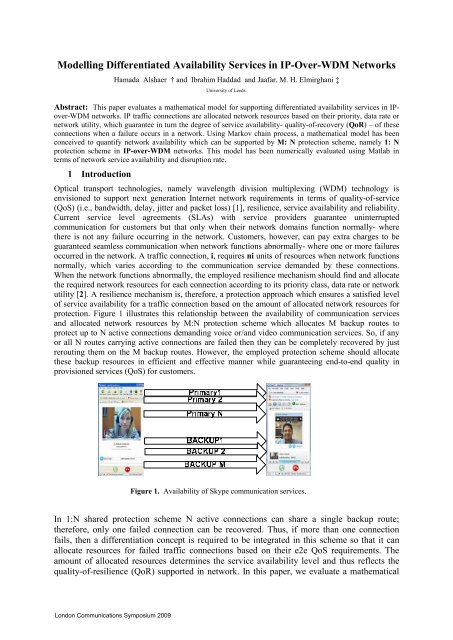
<strong>Modell<strong>in</strong>g</strong> <strong>Differentiated</strong> <strong>Availability</strong> <strong>Services</strong> <strong>in</strong> <strong>IP</strong>-<strong>Over</strong>-<strong>WDM</strong> NetworksHamada Alshaer † and Ibrahim Haddad and Jaafar. M. H. Elmirghani ‡University of Leeds.Abstract: This paper evaluates a mathematical model for support<strong>in</strong>g differentiated availability services <strong>in</strong> <strong>IP</strong>over-<strong>WDM</strong>networks. <strong>IP</strong> traffic connections are allocated network resources based on their priority, data rate ornetwork utility, which guarantee <strong>in</strong> turn the degree of service availability- quality-of-recovery (QoR) – of theseconnections when a failure occurs <strong>in</strong> a network. Us<strong>in</strong>g Markov cha<strong>in</strong> process, a mathematical model has beenconceived to quantify network availability which can be supported by M: N protection scheme, namely 1: Nprotection scheme <strong>in</strong> <strong>IP</strong>-over-<strong>WDM</strong> networks. This model has been numerically evaluated us<strong>in</strong>g Matlab <strong>in</strong>terms of network service availability and disruption rate.1 IntroductionOptical transport technologies, namely wavelength division multiplex<strong>in</strong>g (<strong>WDM</strong>) technology isenvisioned to support next generation Internet network requirements <strong>in</strong> terms of quality-of-service(QoS) (i.e., bandwidth, delay, jitter and packet loss) [1], resilience, service availability and reliability.Current service level agreements (SLAs) with service providers guarantee un<strong>in</strong>terruptedcommunication for customers but that only when their network doma<strong>in</strong>s function normally- wherethere is not any failure occurr<strong>in</strong>g <strong>in</strong> the network. Customers, however, can pay extra charges to beguaranteed seamless communication when network functions abnormally- where one or more failuresoccurred <strong>in</strong> the network. A traffic connection, i, requires ni units of resources when network functionsnormally, which varies accord<strong>in</strong>g to the communication service demanded by these connections.When the network functions abnormally, the employed resilience mechanism should f<strong>in</strong>d and allocatethe required network resources for each connection accord<strong>in</strong>g to its priority class, data rate or networkutility [2]. A resilience mechanism is, therefore, a protection approach which ensures a satisfied levelof service availability for a traffic connection based on the amount of allocated network resources forprotection. Figure 1 illustrates this relationship between the availability of communication servicesand allocated network resources by M:N protection scheme which allocates M backup routes toprotect up to N active connections demand<strong>in</strong>g voice or/and video communication services. So, if anyor all N routes carry<strong>in</strong>g active connections are failed then they can be completely recovered by justrerout<strong>in</strong>g them on the M backup routes. However, the employed protection scheme should allocatethese backup resources <strong>in</strong> efficient and effective manner while guarantee<strong>in</strong>g end-to-end quality <strong>in</strong>provisioned services (QoS) for customers.Figure 1. <strong>Availability</strong> of Skype communication services.In 1:N shared protection scheme N active connections can share a s<strong>in</strong>gle backup route;therefore, only one failed connection can be recovered. Thus, if more than one connectionfails, then a differentiation concept is required to be <strong>in</strong>tegrated <strong>in</strong> this scheme so that it canallocate resources for failed traffic connections based on their e2e QoS requirements. Theamount of allocated resources determ<strong>in</strong>es the service availability level and thus reflects thequality-of-resilience (QoR) supported <strong>in</strong> network. In this paper, we evaluate a mathematicalLondon Communications Symposium 2009
model which can describe differentiated availability services support and disruption servicesrate <strong>in</strong> 1:N protection scheme.2. Markov cha<strong>in</strong> representation of 1:N protection schemeFigure 2 depicts Markov cha<strong>in</strong> process which describes the different states of 1:N protection scheme.Every state <strong>in</strong> S = {0, f … f+1} represents the number of paths which undergoes a failure <strong>in</strong> thenetwork. A forward state transition occurs with exponential <strong>in</strong>ter-arrival distribution of path failureswith mean time to fail (MTTF) rate (1/λ ), which is the time experienced by a network element(path/node) to fail. A backward state transition occurs with exponential distribution of mean time torepair (MTTR) at rate (1/ µ ). So, λ represents the rate at which active connections <strong>in</strong> the networkare decreas<strong>in</strong>g by mov<strong>in</strong>g from one state to the next, and µ is the rate at which failed connections arerepaired by mov<strong>in</strong>g from one state to the previous one. State 0 represents the stationary state of thetransition diagram shown <strong>in</strong> Figure 2. When Markov process moves from state 1 to state 2, the rate ofpath failure <strong>in</strong> this case is (Nλ1), because two failures have occurred <strong>in</strong> the network. It returns back tothe previous state 1 at exponential rate 2 µ 2 , <strong>in</strong>dicat<strong>in</strong>g that one of the two failed paths has beenrepaired and so the system moves from state 2 to state 1 where only a s<strong>in</strong>gle failure still persists <strong>in</strong> thenetwork. The same reason<strong>in</strong>g applies to the rest of Markov cha<strong>in</strong> states. If more than one path fails,then there is a probability that at least one connection will be disconnected, thus multiple failures canbe repaired at a repair rate αµ, where α ≥ 1.( λNλN + 1) 012λf −1λ fµ 2αµ12Nαµ ( N + 1) αµ f + 1fFigure 2. Markov cha<strong>in</strong> process transition diagram.The availability of a network element can be calculated as follows [3,4]:where ρ = λ / µ .MTTF 1/ λ 1A == =(1)MTTF + MTTR 1/ λ + 1/ µ 1+ρ3. Connection Priority-based <strong>Differentiated</strong> <strong>Availability</strong> <strong>Services</strong>Based on Markov process shown <strong>in</strong> Figure 2, the connection unavailability depends on the number offailures occurred <strong>in</strong> the network at each state. For example, when the network enters state 2 (i.e., f =2),then based on 1: N protection scheme, either two primary paths have failed or one primary and theshared backup path have failed. Whatever the case is, there will be one unavailable connection, if f >1. The same applies when the network enters state f, where the number of unavailable connectionsbecomes f-1. Let p(f) represents the fraction of time dur<strong>in</strong>g which the network stays at state f, then thesteady-state probability of f paths have failed out of N+1 follows a b<strong>in</strong>omial distribution and thus canbe expressed as [4][3]:f -1⎛ N + 1⎞λ ⎛ λ ⎞p ( f ) = ⎜ ⎟ ⎜ ⎟ p (0) , 1 ≤ f ≤ N + 1 (2)⎝ f ⎠ µ ⎝ αµ ⎠p ( 0 )− 1⎡N + 1⎛ λ ⎞⎤= ⎢1+ α ⎜ 1 + ⎟ - α ⎥⎢⎥⎣⎝ αµ ⎠⎦(3)London Communications Symposium 2009
where α represents the failure recovery <strong>in</strong>crement factor (crew repair time). Based on equations 2 and3, [3,4] derived the connection unavailability <strong>in</strong> 1: N shared protection scheme as follows:U ( N , λ , µ , α ) =(N+ 1)Nλ ⎛ λ ⎞⎜ 1 + ⎟µ ⎝ αµ ⎠⎡⎛N ⎢1+ α ⎜ 1 +⎢⎣⎝N + 1⎛ λ ⎞− α ⎜ 1 + ⎟ + α⎝ αµ ⎠N + 1λ ⎞⎤⎟ − α ⎥αµ ⎠⎥⎦Then, the connection availability <strong>in</strong> 1: N shared protection scheme can be expressed as:A( N , λ,µ , α ) = 1 − U ( N , λ,µ , α )If there are (f) unavailable paths, then the probability that a connection is available [22]P[Z ( f )] =N + 1 −NBased on equations 5 and 6, with some mathematical manipulations, the service disruption rate can bederived as [3, 4]:SDR( N , λ , µ , α )=λ( N⎡N + 1⎛ λ ⎞⎛+ 1 ) ⎢ α ⎜ 1 + ⎟ − α − ⎜⎢⎣⎝ αµ ⎠⎝⎡N + 1⎛ λ ⎞N ⎢1+ α ⎜ 1 + ⎟⎢⎣⎝ αµ ⎠4. <strong>Differentiated</strong> availability services modelfλµ⎞ ⎛⎟ ⎜ 1 +⎠ ⎝⎤− α ⎥⎥⎦High priority failed expedited forward<strong>in</strong>g (EF) connections contend with low priority failedconnections to have access to the shared backup path. However, EF connections, N EF , can pre-emptBE connections, N BE, when a failure occurs <strong>in</strong> the network, so the unavailability and disruption rate ofEF connections can be calculated based on equations 4,7. However, the availability, unavailability,disruption rate of BE connections depend on: (i) the availability of shared backup path which could bealready allocated to a high priority EF connection (ii) the status of the backup path, whether it isalready failed or not (iii) whether the backup is already allocated to another lower priority BEconnection. In whatever case, this can be represented by two schedul<strong>in</strong>g schemes shar<strong>in</strong>g a commonresource which is the shared backup path <strong>in</strong> our case. So, the objective is to calculate the availabilityof each schedul<strong>in</strong>g scheme, where one schedules BE connections and another schedules EFconnections on the shared backup path. Let us assume that there are N primary paths <strong>in</strong> each scheme,where N EF + N BE = N . Consider that∑Ni − 1λαµ⎞⎟⎠N ⎤⎥⎥⎦(4)(5)(6)(7)ρ iωi = L , where ρ i is described <strong>in</strong> equation 1 and Lis a constant, ω i = U EF if connection i ∈ N EF , and ω i = U BE if i ∈ N BE .U ( N,λ , µ ). N = U EF N EF + U BE N BE =L , thusN NUEFBE = U ( N , λ , µ ). − U EF . (8)NNBy apply<strong>in</strong>g the same idea, the disruption rate of the low priority traffic can be expressed as follows:N NSDREFBE = S ( N , , µ ). − S EF .N BE N BEλ (9)BEBE5. Numerical resultsBased on equations 5, 8 and 9, we have numerically evaluated the average availability and disruptionrate of EF, BE connections <strong>in</strong> differentiated shared protection scheme. This has also compared withthe average availability and disruption rate of the connections served <strong>in</strong> normal protection schemewhich does not differentiate among traffic connections when a failure occurs <strong>in</strong> the network. Figure 3London Communications Symposium 2009
shows that EF traffic connections have better service availability than BE connections and thoseserved without any protection. This result along with that shown <strong>in</strong> Figure 4 substantiate our claim thattraffic connections can enjoy better service availability and less service disruption rate by us<strong>in</strong>g adedicated protection scheme, though backup resources should be effectively allocated for trafficconnections based on their QoS requirements.10.99981:5 <strong>Differentiated</strong> Shared Protection SchemeEqual connection protection schemeBE Connection protection schemeEF connection protection scheme120100<strong>Differentiated</strong> Disruption servicesEqual connection protectionEF connection protectionBE connection protectionA v e ra g e C o n n e c tio n A v a ila b ility0.99960.99940.99920.999A v e ra g e d i s ru p t io n ra t e p e r y e a r8060400.9988200.9986600 800 1000 1200 1400 1600 1800 2000Path Length (km)00 500 1000 1500 2000 2500 3000 3500 4000 4500 5000Path Length (km)Figure 3. Average availabilityFigure 4. Average disruption rate.6. ConclusionBy allocat<strong>in</strong>g enough backup network resources, traffic connections can be recovered and hencecustomers can enjoy guaranteed service availability. In this paper, we analyzed a mathematical modelwhich can differentiate availability and disruption services <strong>in</strong> <strong>IP</strong>/<strong>WDM</strong> networks. This model canprovide different configuration sett<strong>in</strong>gs for service providers, which can be used to control the amountof allocated network resources for protect<strong>in</strong>g traffic connections based on their QoS requirements.<strong>Availability</strong> services as well as disruption services rate can be improved by <strong>in</strong>creas<strong>in</strong>g the repair rate;however, this may <strong>in</strong>crease the total network cost operation. As a next step, we will <strong>in</strong>troducedifferentiated resilience mechanisms for efficiently protect<strong>in</strong>g dynamic traffic.References[1] N. Golmie, T. Ndousse and D. Sue. A differentiated optical services model for <strong>WDM</strong> networks.IEEE Communication Magaz<strong>in</strong>e, vol. 38, no. 2, pp. 68–73, Feb. 2000.[2] M.Tacca, A.Fumagalli, A. Paradisi, F. Unghvary et al. <strong>Differentiated</strong> reliability <strong>in</strong> opticalnetworks: theoretical and practical results. Journal of Lightwave Technology, vol. 21, no. 11, pp.2576–2586, Nov. 2003.[13] J.H. Sarker, H. T. Mouftah. Service Reliability with Enhanced Failure Recovery Rate forMultiple Failures <strong>in</strong> Survivable Optical Networks Communications. 24th Biennial Symposium on,Page (s):89 - 92, 24-26 June 2008.[24] J.E.Angus. On comput<strong>in</strong>g mtbf for a k-out-of-n: g repairable system. In IEEE Transactions onReliability, volume Vol37 (3), pages 312-313, August 1988.London Communications Symposium 2009