Physics 241 Lab: RC Circuits â AC Source
Physics 241 Lab: RC Circuits â AC Source
Physics 241 Lab: RC Circuits â AC Source

Create successful ePaper yourself
Turn your PDF publications into a flip-book with our unique Google optimized e-Paper software.
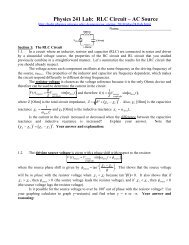
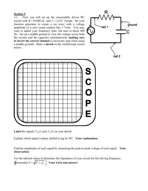
Section 3:3.1. Now you will set up the sinusoidally driven <strong>RC</strong>circuit with R 10,000 , and C 1x10 -7 Farads. Set yourfunction generator to create a sin wave with a voltageamplitude of a nice round number like 3 Volts. You maywant to adjust your frequency later, but start at about 400Hz. Set up a middle ground to view the voltage across boththe resistor and the capacitor simultaneously making sureto invert the correct channel (a necessary step when usinga middle ground). Make a sketch on the oscilloscope screenbelow.<strong>Lab</strong>el the signals V R(t) and V C(t) on your sketchExplain which signal is phase shifted to lag by 90 o . Your explanation:Find the amplitudes of each signal by measuring the peak-to-peak voltage of each signal. Yourobservation:Use the labeled values to determine the impedance of your circuit for this driving frequency.Remember Z R 2 2 C. . Your work and answer: