Physics 241 Lab: RLC Circuit â AC Source
Physics 241 Lab: RLC Circuit â AC Source
Physics 241 Lab: RLC Circuit â AC Source

Create successful ePaper yourself
Turn your PDF publications into a flip-book with our unique Google optimized e-Paper software.
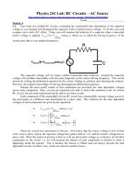
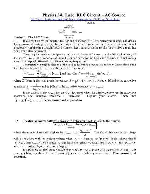
<strong>Physics</strong> <strong>241</strong> <strong>Lab</strong>: <strong>RLC</strong> <strong>Circuit</strong> – <strong>AC</strong> <strong>Source</strong>http://bohr.physics.arizona.edu/~leone/ua/ua_spring_2010/phys<strong>241</strong>lab.htmlName:____________________________Section 1: The <strong>RLC</strong> <strong>Circuit</strong>1.1. In a circuit where an inductor, resistor and capacitor (<strong>RLC</strong>) are connected in series and drivenby a sinusoidal voltage source, the properties of the RC circuit and RL circuit that you studiedpreviously combine in a straightforward manner. Let’s summarize the results for the LRC circuit thatyou should already suspect.The voltage across each component oscillates at the same frequency as the driving frequency ofthe source, drive . The properties of the inductor and capacitor are frequency dependent, which makesthe circuit respond differently to different driving frequencies.The resistor voltage is chosen as the voltage reference because it is the only Ohmic device andtherefore can be used to determine the current in the circuit:V (t) resistor R Z V sourceamplitudesin drivet and therefore I(t) 1 Z V sourcesin drivet,amplitudeR 2 L C 2 . Also, C [Ohm] is the capacitivewhere Z [Ohm] is the total circuit impedance, Z 1reactance C driveC and L [Ohm] is the inductive reactance L driveL .Is the current in the circuit increased or decreased when the difference between the capacitivereactance and inductive reactance is increased? Explain your answer. Note that L C 2 C L 2 . Your answer and explanation:1.2. The driving source voltage is given with a phase shift with respect to the resistor:V (t) source V sourcesin drivet source ,amplitude where the source phase shift is given by source tan 1 L C . This shows that the source voltage R will be in phase with the resistor voltage when L Cbecause tan 1 0 0. It also shows that if L C, then source 0 (the source voltage leads the resistor voltage), and if L C, then source 0(the source voltage lags the resistor voltage).Is it possible for the source voltage to ever be 180 o out of phase with the resistor voltage? Useyour graphing calculator to graph y=arctan(x) and find when y = or –. Your answer andreasoning:
1.3. The capacitor voltage is phase shifted to lag the resistor voltage by 90 o :V (t) capacitor CZ V sourcesin drivet .amplitude 2 The inductor voltage is phase shifted to lead the resistor voltage by 90 o :V (t) inductor LZ V sourcesin drivet .amplitude 2 Sometimes these four boxed (important) voltage equations are rewritten using the fact thatI amplitude V source amplitudeZ:V (t) resistor R I amplitudesin drivetV (t) source V sourceamplitudesin drivet source (no change)V (t) capacitor C I amplitudesin drivet 2 V (t) inductor L I amplitudesin drivet 2 If R = 10 , L = 10 H, C = 10 F, V source amplitude = 10 volts and f drive = 10 Hz, find the voltageamplitudes of the inductor and capacitor. Your work and answers:1.4. It is useful to examine an example graph showing the relationships between each of thecomponent’s voltages:In this example, C is larger than L so that V capacitor amplitude is larger than V inductor amplitude . Note thatV resistor amplitude is larger than the other two voltage amplitudes, which indicates that R is larger than Cand L . This need not be the case since you could always choose to use a smaller resistor in yourcircuit. Since the capacitor voltage lags the resistor voltage by /2 while the inductor voltage leads theresistor voltage by /2, the capacitor and inductor voltages themselves are 180 o out of phase(/2 + /2 = ).
Conservation of energy indicates that the sum of the voltages of the three components at anyinstant of time must equal the voltage of the source at that time. Therefore, if you add the threegraphed voltages, you obtain the source voltage: V source(t) V L(t) V R(t) V C(t). The sum of the threecomponent voltage functions in the previous graph is shown below with a dotted line.Notice that in this example the capacitor voltage amplitude is larger than the inductor voltageamplitude. This causes the source voltage to reach it’s amplitude a little after the resistor. Recall that source tan 1 L C and since C is larger than L , you obtain source < 0. This means that the R source voltage lags the resistor voltage.At driving frequencies where L > C , you find that V L > V C , and this causes the source voltageto lead the resistor voltage.Finally, imagine that you are able to adjust the source frequency while leaving V source,amplitudeconstant. Since I amplitude V source amplitude, the current in the resistor can be maximized by minimizing Z.ZRemember that Z depends on drive since both C and L each depend on drive . Since Z R 2 L C 2 , Z is minimized when C is equal to L so that L – C , = 0. This givesZ minimum = R.The driving frequency at which L – C , = 0 occurs is called the resonant frequency. This can1be found by setting C equal to L so that driveC driveL. Some algebra (that should appear in your1lab report) gives driveresonance L C .1.5. Imagine that you have an <strong>RLC</strong> circuit being driven sinusoidally at resonance. Assume youhave placed the inductor voltage and capacitor voltage on the two channels of your oscilloscope(correctly inverting one of the channels). Make a quick sketch of what you should see on theoscilloscope screen. Think carefully about what the voltage amplitudes should be for these twocomponents at resonance. Your quick sketch below:
Section 2:Let’s practice the math for an example of a sinusoidally driven series <strong>RLC</strong> circuit.2.1. Calculate each of the basic <strong>RLC</strong> circuit parameters in SI units though not necessarily in theorder given.. Write the numerical value with correct SI units for each listed parameter: C L ZV R,amplitudeV C,amplitudeV L,amplitude sourceI amplitude2.2. Next write equations using the numerical results from 2.1 to describe the time-dependentbehavior of each component of the circuit.Write a time-dependent equation for each listed item:V source(t)V R(t) V C(t)V L(t)I(t)Q cap(t)2.3. Imagine that you are free to adjust the driving frequency of the source voltage. Use theprevious results to find the driving frequency that allows the largest current to flow through this <strong>RLC</strong>circuit, f drive.resonanceYour answer:
Section 3: In electronics, you may use the oscilloscope to simultaneously measure the voltage oftwo adjacent components. Connecting your inductor, capacitor and resistor in series should be donewith some consideration of which components you will measure with your oscilloscope since you onlyhave two channels to measure with. The three circuit configuration examples below and the questionsthat follow are used to illustrate this point3.1. In circuit A, which pairs of components can be separately measured on the oscilloscope with amiddle ground technique? (You are free to choose the location of the oscilloscope ground.)Your answer:3.2. In circuit B, which pairs of components cannot be separately measured on the oscilloscope witha middle ground technique? (You are free to choose the location of the oscilloscope ground.)Your answer:3.3. In circuit C, which pairs of components can be separately measured on the oscilloscope with amiddle ground technique? (You are free to choose the location of the oscilloscope ground.)Your answer:Therefore, as you make measurements on the <strong>RLC</strong> circuit, you often have to rearrange the componentsdepending on which two components you wish to measure.3.4. Sketch a circuit configuration along with the proper placement of the three oscilloscope leads(red 1, red 2 and ground) in order to be able to separately measure the time dependence of the solenoidand resistor simultaneously.Your complete sketch:3.5. Sketch a circuit configuration along with the proper placement of the three oscilloscope leads(red 1, red 2 and ground) in order to be able to separately measure the time dependence of the sourceand resistor simultaneously.Your complete sketch:
Section 4: The explanation of the 90 o phase shifts of the inductor and capacitor voltages from theresistor voltage can be explained using calculus.Conservation of energy for the sinusoidally driven <strong>RLC</strong> circuit gives:V source(t) V L(t) V R(t) V C(t).Substituting Ohm’s Law V R(t) I(t) R, the definition of inductance V L(t) L dI(t) and the definitiondtof capacitance V C(t) Q(t)C gives:V source(t) L dI(t)dt RI(t) Q(t) . resistor term Cinductor termcapacitor termFirst notice that first two terms on the right hand side of the equation show that the timedependence of the inductor is related to the resistor by a time derivative,V source(t) L dI(t) RI(t) Q(t)dtC . the inductor voltage is proportional to thetime derivative of the resistor voltageSince the resistor voltage is described by a sine function, V (t) resistor V resistoramplitudesin drivet, the inductorvoltage must be described by a cosine function. But the cosine function leads the sine function by /2,so the inductor voltage leads the resistor voltage by /2.Next remember the definition of current I(t) dQ(t) to find thatdtV source(t) L dI(t) R dQ(t) Q(t) . dt dt Cinductor term resistor term capacitor termNotice that the second two terms on the right hand side show that the time dependence of the capacitorvoltage is related to the antiderivative of the resistor voltage,V source(t) L dI(t) R dQ(t) Q(t)dtdt C the capacitor voltage is proportional to theantiderivative of the resistor voltageSince the resistor voltage is described by a sine function, V (t) resistor V resistoramplitudesin drivet, the capacitorvoltage must be described by a negative cosine function. But the negative cosine function lags thesine function by /2, so the capacitor voltage lags the resistor voltage by /2.4.1. Prove that you truly understand this argument by using the definition of current to rewrite theinductor term with a second time derivative of charge, compare this to the capacitor term and explainwhy the inductor and capacitor are 180 o out of phase. Your work and explanations:
Section 5: There is a related circuit that should also be mentioned, the LC circuit (undriven butwith an initially charged capacitor).Imagine that the capacitor was initially charged and placed into this circuit. At the instantbefore charge began flowing from the capacitor, there would be an electric field inside the capacitorand no fields or current inside the inductor.The electric field in the capacitor contains energy, E energy of 1capacitor 2 CV 2 . As charge begins to flowE-fieldfrom the capacitor, energy stored in the electric field inside the capacitor decreases. However, there isno resistor in the circuit to remove energy by creating heat so the total energy of the circuit must beconserved. Where does this energy go?As current begins to flow through the inductor, the solenoid will have a magnetic field createdinside it. The energy stored in the inductor’s magnetic field is E energy of 1inductor 2 LI 2 . The maximum currentB-fieldwill be reached at the moment the capacitor is completely discharged. This means that the momentwhen all the charge has left the capacitor, all the energy stored in the electric field inside the capacitorwill have been transformed into energy stored in the magnetic field inside the inductor,E energy of E energy of.capacitor inductorE-field B-fieldAfter some time, the charge will flow back onto the capacitor (in the reverse direction) and thecurrent will momentarily return to zero, E energy of E energy of. And so it will go, energy swinging backcapacitor inductorE-field B-fieldand forth between the electric field of the capacitor and the magnetic field of the inductor, but at alltimes the total energy is conserved E total.energy E energy ofcapacitorE-field E energy ofinductorB-field5.1. Use the same process part 4 of the lab to write an equation relating Q(t) and d 2 Q(t)dt 2 for theundriven LC circuit. (Simply plug in zero for the missing components.) Your work and answer:
Section 6: Extra lab technique tips.An <strong>RLC</strong> circuit has a resonant driving frequency f resonance that maximizes the circuit currentamplitude. Therefore, a plot of the current amplitude vs. driving frequency will show peak currentamplitude at the resonant driving frequency. However, this graph can appear different depending onthe resistance used in the circuit:The sharpness of the resonance peak is measure by the quality factor Q. The larger the qualityfactor, the sharper the peak. Q is found to be given as Q resonance Lfor an <strong>RLC</strong> circuit in seriesRdriven sinusoidally.In today’s lab you usually want to use as small of a resistance as possible (while still beingsafe) in order to obtain a nice sharp peak in the current amplitude. This will make it easier to find theresonance frequency. However, it is not always desirable to have a large quality factor. In somemechanical systems (bridges, buildings, etc.) a pronounced response to a driving frequency can causedestruction.The most accurate way to find f resonance is to utilize the fact that at resonance, V R (t) and V source (t)are exactly in phase with each other with equal amplitudes. You should place each of these voltageson your oscilloscope channels and examine an XY formatted display. The resonance frequency iseasily found because you will see an ellipse when V R (t) and V source (t) are out of phase and a diagonalline when they are in phase. You see a straight line when they are in phase because both voltages mustreach zero simultaneously.Note that if R is chosen small enough, the resistance of the very long wire of the solenoid maybecome an appreciable resistance of the circuit. When this occurs, the amplitude of the resistor voltagewill be smaller than the source voltage amplitude so that you will see a different angle of tilt (not 45 o )of the in phase resonance line shown above. This is because V source V R V resistance of solenoid V L V C.
Section 7: Construct an <strong>RLC</strong> circuit driven by a sinusoidal driving voltage of V source 5 Voltsamplitudewith f drive = 3,500 Hz, R 1 k , C 0.1 F, and L 50 mH. You must keep this drivingfrequency the same until 7.8 of this section of the lab.7.1. Quickly measure the voltage amplitudes of each component separately using a single channelof your oscilloscope. Double check that your source voltage amplitude is 5 Volts first. Record yourobservations:7.2. Now use two-channel observations to simultaneously measure the resistor voltage and theinductor voltage to determine their respective phase shift. Your observed inductor voltage phaseshift:7.3. Now use two-channel observations to simultaneously measure the resistor voltage and thecapacitor voltage to determine their respective phase shift. Your observed capacitor voltage phaseshift:7.4. Now use two-channel observations to simultaneously measure the inductor voltage and thecapacitor voltage to determine their respective phase shift. Your observed capacitor voltage phaseshift:7.5. Now use two-channel observations to simultaneously measure the resistor voltage and thesource voltage to determine their respective phase shift. Note that a phase shift of /2 corresponds to ashift along the time axis of ¼ of oscillation cycle T. Therefore, if t shift is the amount of time lag or timelead that you measure between the resistor amplitude and the source amplitude, you can set up thefollowing equivalent ratios to find the phase shift of the source source ,t shift14 T source. 2This gives source 2 t shift drive t shift.TAnother way to think about how to measure the source voltage phase shift is to examine theextra amount of time it would take for the resistor voltage to come into phase with the source voltage ifthe source voltage was frozen in time:sin drive t t shift sin drivet source .For these sine functions to be equal, their arguments must be equal so that you find source drive t shift.Use this equation to experimentally determine the source voltage phase shift source from theresistor voltage. Your observed source voltage phase shift:7.6. Theoretical calculations: Use the labeled values for inductance, capacitance and resistance thatyou have in your circuit as well as your actual driving frequency to calculate the following <strong>RLC</strong>circuit parameters in SI units. Your work and answers: C L Z resonancef resonance
7.7. Comparing theory and observation: Use your results from 7.6 along with your observed sourcevoltage amplitude to theoretically calculate the voltage amplitudes of the resistor, inductor andcapacitor in SI units. Then compare each of these theoretically computed amplitudes to yourobservations in 7.1. Your calculations, theoretical results and comparisons:7.8. Since P resistor I V resistor V resistor 2, the power converted to heat by the resistor oscillates inRtime as a squared sine function. The average value of a squared sine function over a complete2 oscillation cycle is averagesin( drivet 2 1 2 . This means P resistor 1 V resistor amplitude. Use this formula toaverage 2 Rfind the average power loss of your circuit in SI units. Your answer:7.9. When the driving frequency is at resonance, the voltages of the source and resistor are equaland in phase. Use this fact to search the range of driving frequencies for the resonant drivingfrequency using the technique described in part 6 of this lab. Compare this observed value to yourpredicted value in 7.6. Your observed resonant frequency and comparison:7.10. Collect data in order to make the graph ofI amplitudevs. f drive . A poor example is shown with a largeresistance is shown. Collect your data below andconstruct your graph on graph paper now:
Section 8: (Open-ended question / creative lab design)Pretend that you are an old-timey inventor. You have alreadydiscovered the coiled wire device (now called inductor) and the metallicparallel plates device (now called capacitor). Resistors were discoveredby a competitor of yours. It is still a sore subject around the workshop.You have begun to combine these new components together inorder to observe their compound behavior. You already found that whenthe inductor and capacitor are combined in series and driven sinusoidally,the circuit produces a special resonant frequency where the current in thecircuit is a maximum. This means that civilization can now makeelectronics that “select” specific driving frequencies and “suppress”frequencies far from resonance.You should try to find the behavior of the current through the circuit for various drivingfrequencies. Try to deduce why this circuit may be said to have an “antiresonant frequency” and seeif you can find it.Now you try combining the inductor and capacitor in parallel and drive them sinusoidally (seefigure). What electrical possibilities might this new compound device hold for the future of mankind?Well, use your anachronistic oscilloscope to find out.At the following prompts, design an experiment to find the behavior of a parallel <strong>RLC</strong> circuitthat is sinusoidally driven. Then implement your experiment and record your observations. You may“cheat” by talking to other groups for ideas, but not “cheat” by already knowing the answer or lookingit up.Your planned experiment, sketch of actual implementation and any theoretical calculations:Your observations:Your explanations & conclusion:I, the physics <strong>241</strong> laboratory TA, have examined this worksheet and found it to be thoroughlycompleted excepting any sections that I have marked herein. TA signature: ____________________
Report Guidelines: Write a separate section using the labels and instructions provided below. Youmay add diagrams and equations by hand to your final printout. However, images, text or equationsplagiarized from the internet are not allowed! Title – A catchy title worth zero points so make it fun. Goals – Write a 3-4 sentence paragraph stating the experimental goals of the lab (the bigpicture). Do NOT state the learning goals (keep it scientific). [~1-point] Concepts & Equations – [~9-points] Be sure to write a separate paragraph to explain each ofthe following concepts. Explain the meaning and use of the four time dependent equations describing thecomponent voltages. Explain the meaning and use of the resonant frequency. Explain how energy is stored in a capacitor and how energy is stored in an inductor. Explain how to experimentally find an unknown inductance using an <strong>RLC</strong> circuit. Derive the equation for the resonant frequency. Derive the phase shifts of the inductor and capacitor using calculus. Derive why source 2 t shift.TProcedure & Results – Do not write this section. [~0-points]Conclusion – Write at least three paragraphs where you analyze and interpret the results youobserved or measured based upon your previous discussion of concepts and equations. It is allright to sound repetitive since it is important to get your scientific points across to your reader.Write a separate paragraph analyzing and interpreting your results from your open-endedexperiment. Do NOT write personal statements or feeling about the learning process (keep itscientific). [~5-points]Graphs – All graphs must be neatly hand-drawn during class, fill an entire sheet of graphpaper, include a title, labeled axes, units on the axes, and the calculated line of best fit ifapplicable. [5-points]o The graphs from section 7.10.Worksheet – thoroughly completed in class and signed by your TA. [~5-points]
Introductory Electricity & Magnetism <strong>Lab</strong>oratory Learning Outcomes:Introductory electricity & magnetism laboratory students should be prepared for leadership roles inan increasingly diverse, technological and highly competitive world. To this end, these studentsshould… Understand the role of science in our society – The resonance behavior of an <strong>RLC</strong> circuit. Have a firm grasp of the theories that form the basis of electricity and magnetism –trigonometric functions modeling a complex circuit. Be able to apply the principles of physics to solve real world problems – Design an experimentto determine the anti-resonant behavior of an multiple-component circuit. Be familiar with basic laboratory equipment, and should be able to design and carry outexperiments to answer questions or to demonstrate principles. – Skills developed throughoutlab especially the open-ended component. Use of modern digital oscilloscope. Be able to communicate their results through written reports – See the general report writingguidelines in the syllabus and the specific report writing guidelines at the end of the handout.Graduates of the introductory electricity & magnetism laboratory program should… Have a broad education that will allow them to succeed in diverse fields such as business, law,medicine, science writing, etc. – Writing skills, critical thinking skills, creative problem-solvingskills, communicating ideas & information, teamwork skills, leadership skills, working withtime constraints. Have mastered the introductory theoretical techniques and electricity and magnetismexperimental techniques that are commonly expected for students at this level. – Across theworld, all introductory electricity and magnetism students must be able too Use a digital oscilloscope to measure rapidly changing voltages.o Build circuits and measure their properties. Be familiar with the principles and practice of engineering and should be able to apply theirknowledge to solve state of the art problems, both individually and as part of a team. –Individuals must be able to build and test simple circuits. Teams must devise an experiment todiscover the anti-resonance of a parallel <strong>RLC</strong> circuit.
Teaching Tips:o V vs. t graph of components for LRC circuit.o How voltage amplitude of components can exceed the source amplitude via subtraction.o How resonance is achieved by minimizing the impedance.o How R affects the “width” of the resonance.Demonstrate together: The authentic assessment to explain hazards.Instructional Equipment Needed: