Physics 241 Lab: RLC Circuit â AC Source
Physics 241 Lab: RLC Circuit â AC Source
Physics 241 Lab: RLC Circuit â AC Source

You also want an ePaper? Increase the reach of your titles
YUMPU automatically turns print PDFs into web optimized ePapers that Google loves.
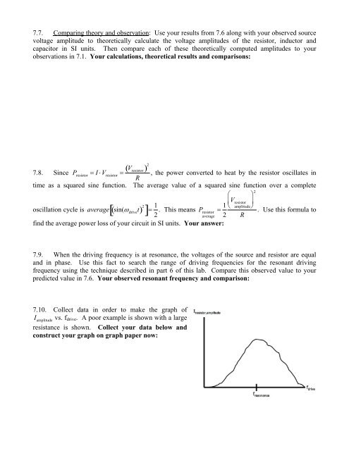
7.7. Comparing theory and observation: Use your results from 7.6 along with your observed sourcevoltage amplitude to theoretically calculate the voltage amplitudes of the resistor, inductor andcapacitor in SI units. Then compare each of these theoretically computed amplitudes to yourobservations in 7.1. Your calculations, theoretical results and comparisons:7.8. Since P resistor I V resistor V resistor 2, the power converted to heat by the resistor oscillates inRtime as a squared sine function. The average value of a squared sine function over a complete2 oscillation cycle is averagesin( drivet 2 1 2 . This means P resistor 1 V resistor amplitude. Use this formula toaverage 2 Rfind the average power loss of your circuit in SI units. Your answer:7.9. When the driving frequency is at resonance, the voltages of the source and resistor are equaland in phase. Use this fact to search the range of driving frequencies for the resonant drivingfrequency using the technique described in part 6 of this lab. Compare this observed value to yourpredicted value in 7.6. Your observed resonant frequency and comparison:7.10. Collect data in order to make the graph ofI amplitudevs. f drive . A poor example is shown with a largeresistance is shown. Collect your data below andconstruct your graph on graph paper now: