Physics 241 Lab: RLC Circuit â AC Source
Physics 241 Lab: RLC Circuit â AC Source
Physics 241 Lab: RLC Circuit â AC Source

You also want an ePaper? Increase the reach of your titles
YUMPU automatically turns print PDFs into web optimized ePapers that Google loves.
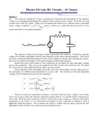
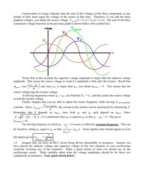
Conservation of energy indicates that the sum of the voltages of the three components at anyinstant of time must equal the voltage of the source at that time. Therefore, if you add the threegraphed voltages, you obtain the source voltage: V source(t) V L(t) V R(t) V C(t). The sum of the threecomponent voltage functions in the previous graph is shown below with a dotted line.Notice that in this example the capacitor voltage amplitude is larger than the inductor voltageamplitude. This causes the source voltage to reach it’s amplitude a little after the resistor. Recall that source tan 1 L C and since C is larger than L , you obtain source < 0. This means that the R source voltage lags the resistor voltage.At driving frequencies where L > C , you find that V L > V C , and this causes the source voltageto lead the resistor voltage.Finally, imagine that you are able to adjust the source frequency while leaving V source,amplitudeconstant. Since I amplitude V source amplitude, the current in the resistor can be maximized by minimizing Z.ZRemember that Z depends on drive since both C and L each depend on drive . Since Z R 2 L C 2 , Z is minimized when C is equal to L so that L – C , = 0. This givesZ minimum = R.The driving frequency at which L – C , = 0 occurs is called the resonant frequency. This can1be found by setting C equal to L so that driveC driveL. Some algebra (that should appear in your1lab report) gives driveresonance L C .1.5. Imagine that you have an <strong>RLC</strong> circuit being driven sinusoidally at resonance. Assume youhave placed the inductor voltage and capacitor voltage on the two channels of your oscilloscope(correctly inverting one of the channels). Make a quick sketch of what you should see on theoscilloscope screen. Think carefully about what the voltage amplitudes should be for these twocomponents at resonance. Your quick sketch below: