Physics 241 Lab: RLC Circuit â AC Source
Physics 241 Lab: RLC Circuit â AC Source
Physics 241 Lab: RLC Circuit â AC Source

You also want an ePaper? Increase the reach of your titles
YUMPU automatically turns print PDFs into web optimized ePapers that Google loves.
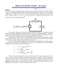
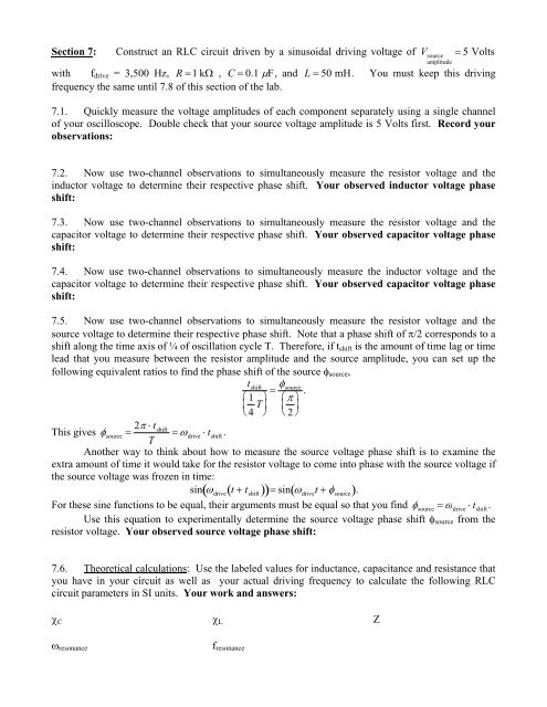
Section 7: Construct an <strong>RLC</strong> circuit driven by a sinusoidal driving voltage of V source 5 Voltsamplitudewith f drive = 3,500 Hz, R 1 k , C 0.1 F, and L 50 mH. You must keep this drivingfrequency the same until 7.8 of this section of the lab.7.1. Quickly measure the voltage amplitudes of each component separately using a single channelof your oscilloscope. Double check that your source voltage amplitude is 5 Volts first. Record yourobservations:7.2. Now use two-channel observations to simultaneously measure the resistor voltage and theinductor voltage to determine their respective phase shift. Your observed inductor voltage phaseshift:7.3. Now use two-channel observations to simultaneously measure the resistor voltage and thecapacitor voltage to determine their respective phase shift. Your observed capacitor voltage phaseshift:7.4. Now use two-channel observations to simultaneously measure the inductor voltage and thecapacitor voltage to determine their respective phase shift. Your observed capacitor voltage phaseshift:7.5. Now use two-channel observations to simultaneously measure the resistor voltage and thesource voltage to determine their respective phase shift. Note that a phase shift of /2 corresponds to ashift along the time axis of ¼ of oscillation cycle T. Therefore, if t shift is the amount of time lag or timelead that you measure between the resistor amplitude and the source amplitude, you can set up thefollowing equivalent ratios to find the phase shift of the source source ,t shift14 T source. 2This gives source 2 t shift drive t shift.TAnother way to think about how to measure the source voltage phase shift is to examine theextra amount of time it would take for the resistor voltage to come into phase with the source voltage ifthe source voltage was frozen in time:sin drive t t shift sin drivet source .For these sine functions to be equal, their arguments must be equal so that you find source drive t shift.Use this equation to experimentally determine the source voltage phase shift source from theresistor voltage. Your observed source voltage phase shift:7.6. Theoretical calculations: Use the labeled values for inductance, capacitance and resistance thatyou have in your circuit as well as your actual driving frequency to calculate the following <strong>RLC</strong>circuit parameters in SI units. Your work and answers: C L Z resonancef resonance