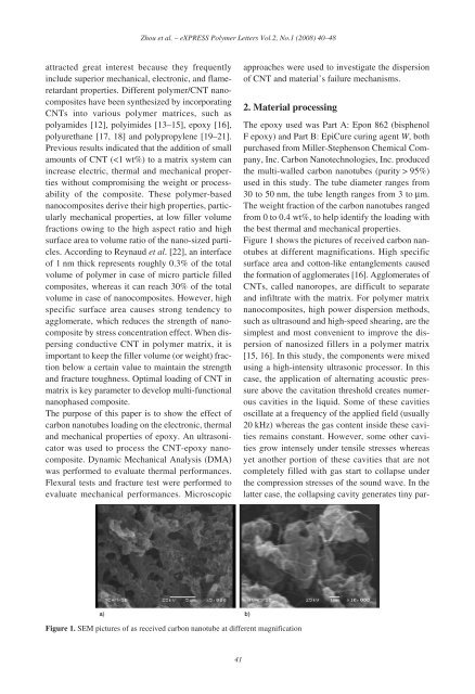
Zhou et al. – eXPRESS Polymer Letters Vol.2, No.1 (2008) 40–48attracted great <strong>in</strong>terest because they frequently<strong>in</strong>clude superior <strong>mechanical</strong>, electronic, <strong>and</strong> flameretardant<strong>properties</strong>. Different polymer/CNT nanocompositeshave been synthesized by <strong>in</strong>corporat<strong>in</strong>gCNTs <strong>in</strong>to various polymer matrices, such aspolyamides [12], polyimides [13–15], epoxy [16],polyurethane [17, 18] <strong>and</strong> polypropylene [19–21].Previous results <strong>in</strong>dicated that the addition <strong>of</strong> smallamounts <strong>of</strong> CNT ( 95%)used <strong>in</strong> this study. The tube diameter ranges from30 to 50 nm, the tube length ranges from 3 to μm.The weight fraction <strong>of</strong> the carbon nanotubes rangedfrom 0 to 0.4 wt%, to help identify the load<strong>in</strong>g withthe best <strong>thermal</strong> <strong>and</strong> <strong>mechanical</strong> <strong>properties</strong>.Figure 1 shows the pictures <strong>of</strong> received carbon nanotubesat different magnifications. High specificsurface area <strong>and</strong> cotton-like entanglements causedthe formation <strong>of</strong> agglomerates [16]. Agglomerates <strong>of</strong>CNTs, called nanoropes, are difficult to separate<strong>and</strong> <strong>in</strong>filtrate with the matrix. For polymer matrixnanocomposites, high power dispersion methods,such as ultrasound <strong>and</strong> high-speed shear<strong>in</strong>g, are thesimplest <strong>and</strong> most convenient to improve the dispersion<strong>of</strong> nanosized fillers <strong>in</strong> a polymer matrix[15, 16]. In this study, the components were mixedus<strong>in</strong>g a high-<strong>in</strong>tensity ultrasonic processor. In thiscase, the application <strong>of</strong> alternat<strong>in</strong>g acoustic pressureabove the cavitation threshold creates numerouscavities <strong>in</strong> the liquid. Some <strong>of</strong> these cavitiesoscillate at a frequency <strong>of</strong> the applied field (usually20 kHz) whereas the gas content <strong>in</strong>side these cavitiesrema<strong>in</strong>s constant. However, some other cavitiesgrow <strong>in</strong>tensely under tensile stresses whereasyet another portion <strong>of</strong> these cavities that are notcompletely filled with gas start to collapse underthe compression stresses <strong>of</strong> the sound wave. In thelatter case, the collaps<strong>in</strong>g cavity generates t<strong>in</strong>y par-Figure 1. SEM pictures <strong>of</strong> as received carbon nanotube at different magnification41
Zhou et al. – eXPRESS Polymer Letters Vol.2, No.1 (2008) 40–48ticles <strong>of</strong> debris <strong>and</strong> the energy <strong>of</strong> the collapsed oneis transformed <strong>in</strong>to pressure pulses. It is noteworthythat the formation <strong>of</strong> the debris further facilitatesthe development <strong>of</strong> cavitation. It is assumed thatacoustic cavitation <strong>in</strong> liquids develops accord<strong>in</strong>g toa cha<strong>in</strong> reaction. Therefore, <strong>in</strong>dividual cavities onreal nuclei develop so rapidly that with<strong>in</strong> a fewmicroseconds an active cavitation region is createdclose to the source <strong>of</strong> the ultrasound probe. Thedevelopment <strong>of</strong> cavitation processes <strong>in</strong> the ultrasonicallyprocessed melt creates favorable conditionsfor the <strong>in</strong>tensification <strong>of</strong> various physicochemicalprocesses. Acoustic cavitation acceleratesheat <strong>and</strong> mass transfer processes such as diffusion,wett<strong>in</strong>g, dissolution, dispersion, <strong>and</strong> emulsification.The uniform dispersion <strong>of</strong> CNF was observed <strong>in</strong>sonication process [8].Pre-calculated amounts <strong>of</strong> carbon nanotubes <strong>and</strong>Epon 862 res<strong>in</strong> were carefully weighed <strong>and</strong> mixedtogether <strong>in</strong> a beaker. A high-<strong>in</strong>tensity, ultrasonicirradiation mixed the CNTs <strong>and</strong> res<strong>in</strong> for an hour onpulse mode, 50 sec on/25 sec <strong>of</strong>f (Ti-horn, 20 kHzSonics Vibra Cell, Sonics & Materials, Inc). Thebeaker conta<strong>in</strong><strong>in</strong>g the mixture was submerged <strong>in</strong> anice bath to keep it cool dur<strong>in</strong>g the sonicationprocess. Once the irradiation was complete, Epi-Cure cur<strong>in</strong>g agent W was added to the modifiedres<strong>in</strong> <strong>and</strong> mixed us<strong>in</strong>g a high-speed <strong>mechanical</strong>stirrer for about 10 m<strong>in</strong>utes. The mix ratio <strong>of</strong>Epon 862 <strong>and</strong> W agent was 100:26. The mix<strong>in</strong>g <strong>of</strong>epoxy <strong>and</strong> cur<strong>in</strong>g agent <strong>in</strong>itially produced highlyreactive, volatile vapor bubbles, which could createvoids <strong>and</strong> detrimentally affect the <strong>properties</strong> <strong>of</strong> thef<strong>in</strong>al product. To reduce the chance <strong>of</strong> voids, theliquid was preheated to 80°C to reduce its viscosity<strong>and</strong> a high vacuum system was used for about30 m<strong>in</strong>utes. After the bubbles were completelyremoved, the mixture was transferred to plastic<strong>and</strong>Teflon-coated metal rectangular molds <strong>and</strong>cured for 4 hours at 120°C. The cured material wasthen trimmed. F<strong>in</strong>ally, test samples were mach<strong>in</strong>edfor <strong>thermal</strong> <strong>and</strong> <strong>mechanical</strong> characterization <strong>and</strong> allpanels were post-cured at 170°C for 4 hours <strong>in</strong> aL<strong>in</strong>dberg/Blue Mechanical Convection Oven.3. Experimental results <strong>and</strong> discussions3.1. Electric <strong>properties</strong>The <strong>electrical</strong> <strong>properties</strong> <strong>of</strong> the neat <strong>and</strong> nanophasedepoxy were measured by us<strong>in</strong>g an Agilent4294-A Precision Impedance analyzer. The compositeswere cut <strong>in</strong>to rectangular bars with dimension<strong>of</strong> 8 mm × 4mm× 1 mm (length, width <strong>and</strong>thickness) by a diamond saw. The two end surfaceswere fully coated with gold as electrodes, which isabout 4 mm 2 . The measurement was carried at frequenciesfrom 100 Hz to 10 MHz at room temperature.In the measurement, the impedance <strong>of</strong> thesample at each frequency was measured <strong>and</strong>recorded. The resistivity <strong>of</strong> the composites was calculatedus<strong>in</strong>g the measured impedance <strong>and</strong> thegeometry <strong>of</strong> the sample.The application <strong>of</strong> conductive nano-particles to an<strong>in</strong>sulat<strong>in</strong>g polymer matrix is supposed to <strong>in</strong>duce an<strong>electrical</strong> conductivity, when the volume fractionexceeds the percolation threshold [23]. Generally,the percolation threshold is considered to be lowerfor fiber-shaped fillers (high aspect ratio) than forspherical particles. The results shown <strong>in</strong> Figure 2are the resistivity <strong>of</strong> the neat <strong>and</strong> nanophased epoxyat frequency 100 Hz. In this figure, the impedanceresults <strong>of</strong> each material are consistent, even somesamples are not very uniform. A dramatic decrease<strong>in</strong> resistivity has been found <strong>in</strong> nanophased epoxy.With only 0.2% CNT, resistivity <strong>of</strong> epoxydecreased from 10 14 Ω·m <strong>of</strong> neat epoxy to 10 Ω·m.Figure 2. Effect <strong>of</strong> CNT weight fraction on resistivity <strong>of</strong>epoxy42