Improvement in electrical, thermal and mechanical properties of ...
Improvement in electrical, thermal and mechanical properties of ...
Improvement in electrical, thermal and mechanical properties of ...

Create successful ePaper yourself
Turn your PDF publications into a flip-book with our unique Google optimized e-Paper software.
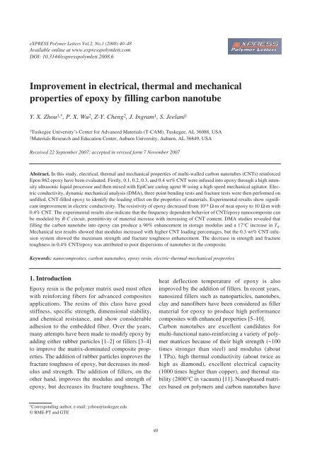
eXPRESS Polymer Letters Vol.2, No.1 (2008) 40–48Available onl<strong>in</strong>e at www.expresspolymlett.comDOI: 10.3144/expresspolymlett.2008.6<strong>Improvement</strong> <strong>in</strong> <strong>electrical</strong>, <strong>thermal</strong> <strong>and</strong> <strong>mechanical</strong><strong>properties</strong> <strong>of</strong> epoxy by fill<strong>in</strong>g carbon nanotubeY. X. Zhou 1,* , P. X. Wu 2 , Z-Y. Cheng 2 , J. Ingram 1 , S. Jeelani 11 Tuskegee University’s Center for Advanced Materials (T-CAM), Tuskegee, AL 36088, USA2 Materials Research <strong>and</strong> Education Center, Auburn University, Auburn, AL 36849, USAReceived 22 September 2007; accepted <strong>in</strong> revised form 7 November 2007Abstract. In this study, <strong>electrical</strong>, <strong>thermal</strong> <strong>and</strong> <strong>mechanical</strong> <strong>properties</strong> <strong>of</strong> multi-walled carbon nanotubes (CNTs) re<strong>in</strong>forcedEpon 862 epoxy have been evaluated. Firstly, 0.1, 0.2, 0.3, <strong>and</strong> 0.4 wt% CNT were <strong>in</strong>fused <strong>in</strong>to epoxy through a high <strong>in</strong>tensityultrasonic liquid processor <strong>and</strong> then mixed with EpiCure cur<strong>in</strong>g agent W us<strong>in</strong>g a high speed <strong>mechanical</strong> agitator. Electricconductivity, dynamic <strong>mechanical</strong> analysis (DMA), three po<strong>in</strong>t bend<strong>in</strong>g tests <strong>and</strong> fracture tests were then performed onunfilled, CNT-filled epoxy to identify the load<strong>in</strong>g effect on the <strong>properties</strong> <strong>of</strong> materials. Experimental results show significantimprovement <strong>in</strong> electric conductivity. The resistivity <strong>of</strong> epoxy decreased from 10 14 Ω·m <strong>of</strong> neat epoxy to 10 Ω·m with0.4% CNT. The experimental results also <strong>in</strong>dicate that the frequency dependent behavior <strong>of</strong> CNT/epoxy nanocomposite canbe modeled by R-C circuit, permittivity <strong>of</strong> material <strong>in</strong>crease with <strong>in</strong>creas<strong>in</strong>g <strong>of</strong> CNT content. DMA studies revealed thatfill<strong>in</strong>g the carbon nanotube <strong>in</strong>to epoxy can produce a 90% enhancement <strong>in</strong> storage modulus <strong>and</strong> a 17°C <strong>in</strong>crease <strong>in</strong> T g.Mechanical test results showed that modulus <strong>in</strong>creased with higher CNT load<strong>in</strong>g percentages, but the 0.3 wt% CNT-<strong>in</strong>fusionsystem showed the maximum strength <strong>and</strong> fracture toughness enhancement. The decrease <strong>in</strong> strength <strong>and</strong> fracturetoughness <strong>in</strong> 0.4% CNT/epoxy was attributed to poor dispersions <strong>of</strong> nanotubes <strong>in</strong> the composite.Keywords: nanocomposites, carbon nanotubes, epoxy res<strong>in</strong>, electric-<strong>thermal</strong>-<strong>mechanical</strong> <strong>properties</strong>1. IntroductionEpoxy res<strong>in</strong> is the polymer matrix used most <strong>of</strong>tenwith re<strong>in</strong>forc<strong>in</strong>g fibers for advanced compositesapplications. The res<strong>in</strong>s <strong>of</strong> this class have goodstiffness, specific strength, dimensional stability,<strong>and</strong> chemical resistance, <strong>and</strong> show considerableadhesion to the embedded fiber. Over the years,many attempts have been made to modify epoxy byadd<strong>in</strong>g either rubber particles [1–2] or fillers [3–4]to improve the matrix-dom<strong>in</strong>ated composite <strong>properties</strong>.The addition <strong>of</strong> rubber particles improves thefracture toughness <strong>of</strong> epoxy, but decreases its modulus<strong>and</strong> strength. The addition <strong>of</strong> fillers, on theother h<strong>and</strong>, improves the modulus <strong>and</strong> strength <strong>of</strong>epoxy, but decreases its fracture toughness. Theheat deflection temperature <strong>of</strong> epoxy is alsoimproved by the addition <strong>of</strong> fillers. In recent years,nanosized fillers such as nanoparticles, nanotubes,clay <strong>and</strong> nan<strong>of</strong>ibers have been considered as fillermaterial for epoxy to produce high performancecomposites with enhanced <strong>properties</strong> [5–10].Carbon nanotubes are excellent c<strong>and</strong>idates formulti-functional nano-re<strong>in</strong>forc<strong>in</strong>g a variety <strong>of</strong> polymermatrices because <strong>of</strong> their high strength (~100times stronger than steel) <strong>and</strong> modulus (about1 TPa), high <strong>thermal</strong> conductivity (about twice ashigh as diamond), excellent <strong>electrical</strong> capacity(1000 times higher than copper), <strong>and</strong> <strong>thermal</strong> stability(2800°C <strong>in</strong> vacuum) [11]. Nanophased matricesbased on polymers <strong>and</strong> carbon nanotubes have*Correspond<strong>in</strong>g author, e-mail: yzhou@tuskegee.edu© BME-PT <strong>and</strong> GTE40
Zhou et al. – eXPRESS Polymer Letters Vol.2, No.1 (2008) 40–48attracted great <strong>in</strong>terest because they frequently<strong>in</strong>clude superior <strong>mechanical</strong>, electronic, <strong>and</strong> flameretardant<strong>properties</strong>. Different polymer/CNT nanocompositeshave been synthesized by <strong>in</strong>corporat<strong>in</strong>gCNTs <strong>in</strong>to various polymer matrices, such aspolyamides [12], polyimides [13–15], epoxy [16],polyurethane [17, 18] <strong>and</strong> polypropylene [19–21].Previous results <strong>in</strong>dicated that the addition <strong>of</strong> smallamounts <strong>of</strong> CNT ( 95%)used <strong>in</strong> this study. The tube diameter ranges from30 to 50 nm, the tube length ranges from 3 to μm.The weight fraction <strong>of</strong> the carbon nanotubes rangedfrom 0 to 0.4 wt%, to help identify the load<strong>in</strong>g withthe best <strong>thermal</strong> <strong>and</strong> <strong>mechanical</strong> <strong>properties</strong>.Figure 1 shows the pictures <strong>of</strong> received carbon nanotubesat different magnifications. High specificsurface area <strong>and</strong> cotton-like entanglements causedthe formation <strong>of</strong> agglomerates [16]. Agglomerates <strong>of</strong>CNTs, called nanoropes, are difficult to separate<strong>and</strong> <strong>in</strong>filtrate with the matrix. For polymer matrixnanocomposites, high power dispersion methods,such as ultrasound <strong>and</strong> high-speed shear<strong>in</strong>g, are thesimplest <strong>and</strong> most convenient to improve the dispersion<strong>of</strong> nanosized fillers <strong>in</strong> a polymer matrix[15, 16]. In this study, the components were mixedus<strong>in</strong>g a high-<strong>in</strong>tensity ultrasonic processor. In thiscase, the application <strong>of</strong> alternat<strong>in</strong>g acoustic pressureabove the cavitation threshold creates numerouscavities <strong>in</strong> the liquid. Some <strong>of</strong> these cavitiesoscillate at a frequency <strong>of</strong> the applied field (usually20 kHz) whereas the gas content <strong>in</strong>side these cavitiesrema<strong>in</strong>s constant. However, some other cavitiesgrow <strong>in</strong>tensely under tensile stresses whereasyet another portion <strong>of</strong> these cavities that are notcompletely filled with gas start to collapse underthe compression stresses <strong>of</strong> the sound wave. In thelatter case, the collaps<strong>in</strong>g cavity generates t<strong>in</strong>y par-Figure 1. SEM pictures <strong>of</strong> as received carbon nanotube at different magnification41
Zhou et al. – eXPRESS Polymer Letters Vol.2, No.1 (2008) 40–48ticles <strong>of</strong> debris <strong>and</strong> the energy <strong>of</strong> the collapsed oneis transformed <strong>in</strong>to pressure pulses. It is noteworthythat the formation <strong>of</strong> the debris further facilitatesthe development <strong>of</strong> cavitation. It is assumed thatacoustic cavitation <strong>in</strong> liquids develops accord<strong>in</strong>g toa cha<strong>in</strong> reaction. Therefore, <strong>in</strong>dividual cavities onreal nuclei develop so rapidly that with<strong>in</strong> a fewmicroseconds an active cavitation region is createdclose to the source <strong>of</strong> the ultrasound probe. Thedevelopment <strong>of</strong> cavitation processes <strong>in</strong> the ultrasonicallyprocessed melt creates favorable conditionsfor the <strong>in</strong>tensification <strong>of</strong> various physicochemicalprocesses. Acoustic cavitation acceleratesheat <strong>and</strong> mass transfer processes such as diffusion,wett<strong>in</strong>g, dissolution, dispersion, <strong>and</strong> emulsification.The uniform dispersion <strong>of</strong> CNF was observed <strong>in</strong>sonication process [8].Pre-calculated amounts <strong>of</strong> carbon nanotubes <strong>and</strong>Epon 862 res<strong>in</strong> were carefully weighed <strong>and</strong> mixedtogether <strong>in</strong> a beaker. A high-<strong>in</strong>tensity, ultrasonicirradiation mixed the CNTs <strong>and</strong> res<strong>in</strong> for an hour onpulse mode, 50 sec on/25 sec <strong>of</strong>f (Ti-horn, 20 kHzSonics Vibra Cell, Sonics & Materials, Inc). Thebeaker conta<strong>in</strong><strong>in</strong>g the mixture was submerged <strong>in</strong> anice bath to keep it cool dur<strong>in</strong>g the sonicationprocess. Once the irradiation was complete, Epi-Cure cur<strong>in</strong>g agent W was added to the modifiedres<strong>in</strong> <strong>and</strong> mixed us<strong>in</strong>g a high-speed <strong>mechanical</strong>stirrer for about 10 m<strong>in</strong>utes. The mix ratio <strong>of</strong>Epon 862 <strong>and</strong> W agent was 100:26. The mix<strong>in</strong>g <strong>of</strong>epoxy <strong>and</strong> cur<strong>in</strong>g agent <strong>in</strong>itially produced highlyreactive, volatile vapor bubbles, which could createvoids <strong>and</strong> detrimentally affect the <strong>properties</strong> <strong>of</strong> thef<strong>in</strong>al product. To reduce the chance <strong>of</strong> voids, theliquid was preheated to 80°C to reduce its viscosity<strong>and</strong> a high vacuum system was used for about30 m<strong>in</strong>utes. After the bubbles were completelyremoved, the mixture was transferred to plastic<strong>and</strong>Teflon-coated metal rectangular molds <strong>and</strong>cured for 4 hours at 120°C. The cured material wasthen trimmed. F<strong>in</strong>ally, test samples were mach<strong>in</strong>edfor <strong>thermal</strong> <strong>and</strong> <strong>mechanical</strong> characterization <strong>and</strong> allpanels were post-cured at 170°C for 4 hours <strong>in</strong> aL<strong>in</strong>dberg/Blue Mechanical Convection Oven.3. Experimental results <strong>and</strong> discussions3.1. Electric <strong>properties</strong>The <strong>electrical</strong> <strong>properties</strong> <strong>of</strong> the neat <strong>and</strong> nanophasedepoxy were measured by us<strong>in</strong>g an Agilent4294-A Precision Impedance analyzer. The compositeswere cut <strong>in</strong>to rectangular bars with dimension<strong>of</strong> 8 mm × 4mm× 1 mm (length, width <strong>and</strong>thickness) by a diamond saw. The two end surfaceswere fully coated with gold as electrodes, which isabout 4 mm 2 . The measurement was carried at frequenciesfrom 100 Hz to 10 MHz at room temperature.In the measurement, the impedance <strong>of</strong> thesample at each frequency was measured <strong>and</strong>recorded. The resistivity <strong>of</strong> the composites was calculatedus<strong>in</strong>g the measured impedance <strong>and</strong> thegeometry <strong>of</strong> the sample.The application <strong>of</strong> conductive nano-particles to an<strong>in</strong>sulat<strong>in</strong>g polymer matrix is supposed to <strong>in</strong>duce an<strong>electrical</strong> conductivity, when the volume fractionexceeds the percolation threshold [23]. Generally,the percolation threshold is considered to be lowerfor fiber-shaped fillers (high aspect ratio) than forspherical particles. The results shown <strong>in</strong> Figure 2are the resistivity <strong>of</strong> the neat <strong>and</strong> nanophased epoxyat frequency 100 Hz. In this figure, the impedanceresults <strong>of</strong> each material are consistent, even somesamples are not very uniform. A dramatic decrease<strong>in</strong> resistivity has been found <strong>in</strong> nanophased epoxy.With only 0.2% CNT, resistivity <strong>of</strong> epoxydecreased from 10 14 Ω·m <strong>of</strong> neat epoxy to 10 Ω·m.Figure 2. Effect <strong>of</strong> CNT weight fraction on resistivity <strong>of</strong>epoxy42
Zhou et al. – eXPRESS Polymer Letters Vol.2, No.1 (2008) 40–48Figure 5. DMA results <strong>of</strong> neat <strong>and</strong> nanophased epoxyFigure 6. Normalized weight vs. temperature curves <strong>of</strong>neat <strong>and</strong> nanophased epoxytangular bars measur<strong>in</strong>g 2 mm × 30 mm × 12 mmby a diamond saw.The loss factor curve, tanδ, <strong>of</strong> the neat epoxy <strong>and</strong>its nanocomposites measured by DMA are shown<strong>in</strong> Figure 5. The peak height <strong>of</strong> loss factor decreasedwith higher CNT content, but the temperaturedeterm<strong>in</strong>ed from the peak position <strong>of</strong> tanδ, T g ,<strong>in</strong>creased 17°C. In addition, the width tanδ <strong>in</strong>creasedwith higher CNT content. Similar results have beenobserved <strong>in</strong> other nanocomposites [21]. Figure 5also shows the DMA plots <strong>of</strong> storage modulus vs.temperature as a function <strong>of</strong> load<strong>in</strong>g carbon nanotubes.The storage modulus steadily <strong>in</strong>creasedwith higher CNT weight percents. The addition <strong>of</strong>0.4 wt% <strong>of</strong> carbon nanotube yielded a 93% <strong>in</strong>crease<strong>of</strong> the storage modulus at 30°C. The high aspectratio <strong>and</strong> elastic modulus <strong>of</strong> CNTs, as compared tonanoclay <strong>and</strong> nanoparticles [7, 8], <strong>in</strong>crease the storagemodulus with smaller amounts <strong>of</strong> CNTs.Thermogravimetric Analysis (TGA) was conductedwith a TA Instruments TGA2950 <strong>in</strong> nitrogen gas ata heat rate <strong>of</strong> 10°C/m<strong>in</strong>, from ambient to 600°C.The TGA samples were cut <strong>in</strong>to small pieces us<strong>in</strong>gan ISOMET Cutter <strong>and</strong> were mach<strong>in</strong>ed us<strong>in</strong>g a<strong>mechanical</strong> gr<strong>in</strong>der to ma<strong>in</strong>ta<strong>in</strong> sample weightsbetween 5–20 mg. Universal Analysis 2000-TAInstruments Inc., a data acquisition system, generatedthe real-time characteristic curves. All TGAtests are run <strong>in</strong> nitrogen gas. Figure 6 shows theTGA results <strong>of</strong> neat <strong>and</strong> nanophased epoxy. Thenormalized weights vs. temperature curves <strong>of</strong> fivematerials overlap. All samples started to decomposearound 340°C <strong>and</strong> completely decomposedaround 460°C. The derivative peaks <strong>of</strong> weight vs.temperature curves show the decomposition temperature.But CNT has little effect on decompositiontemperature <strong>of</strong> epoxy.3.3. Mechanical responseFlexural tests were performed accord<strong>in</strong>g to ASTMD790-86 under a three-po<strong>in</strong>t bend configuration.The tests were conducted <strong>in</strong> a 10 kN servo-hydraulictest<strong>in</strong>g mach<strong>in</strong>e equipped with a Test Ware dataacquisition system. The mach<strong>in</strong>e was run under displacementcontrol mode at a crosshead speed <strong>of</strong>2.0 mm/m<strong>in</strong>. All the tests were performed at roomtemperature. Test samples were cut from the panelsus<strong>in</strong>g a Felker saw fitted with a diamond coatedsteel blade. Five replicate specimens from four differentmaterials were prepared for static flexuretests.Typical stress-stra<strong>in</strong> behavior from the flexuraltests is shown <strong>in</strong> Figure 7. All specimens failedimmediately after the tensile stress reached themaximum value. The stress-stra<strong>in</strong> curves showedconsiderable non-l<strong>in</strong>earity before reach<strong>in</strong>g themaximum stress, but no obvious yield po<strong>in</strong>t wasfound <strong>in</strong> the curves. Five specimens were tested foreach condition; the average <strong>properties</strong> obta<strong>in</strong>edfrom these tests are listed <strong>in</strong> Table 1.Table 1. Mechanical <strong>properties</strong> <strong>of</strong> neat <strong>and</strong> nanophasedepoxyModulus[GPa]Strength[MPa]Failure stra<strong>in</strong>[%]Neat epoxy 2.46 093.5 4.020.1% CNT 2.54 109.0 6.060.2% CNT 2.60 115.0 6.800.3% CNT 2.65 121.0 7.580.4% CNT 2.75 113.0 5.1244
Zhou et al. – eXPRESS Polymer Letters Vol.2, No.1 (2008) 40–48Figure 7. Stress stra<strong>in</strong> curves <strong>of</strong> epoxy <strong>and</strong> CNT/epoxyThe modulus <strong>of</strong> the nanophased epoxy <strong>in</strong>creasescont<strong>in</strong>uously with higher CNT content (Table 1,Figure 7). The tensile modulus improved by 11.7%with an addition <strong>of</strong> 0.4 wt% <strong>of</strong> CNTs. However, thesystem with 0.3 wt% <strong>in</strong>fusion is the best, with a28.3% strength enhancement (Table 1, Figure 7).The strength beg<strong>in</strong>s to decrease with 0.4 wt% load<strong>in</strong>g,although the ga<strong>in</strong> <strong>in</strong> modulus is ma<strong>in</strong>ta<strong>in</strong>ed.See Figure 8 for the relationship between modulus,strength, <strong>and</strong> CNT weight fraction. The dispersion<strong>of</strong> CNTs that restricts the mobility <strong>of</strong> polymercha<strong>in</strong>s under load<strong>in</strong>g improved the modulus <strong>and</strong>strength <strong>in</strong> small load<strong>in</strong>gs. The high aspect ratio,high modulus, strength <strong>of</strong> CNTs also contributed tothe re<strong>in</strong>forcement. However, the decrease <strong>of</strong>strength with high CNT content can be attributed toFigure 8. Effect <strong>of</strong> CNT content on strength <strong>and</strong> modulus<strong>of</strong> neat <strong>and</strong> nanophased epoxyfollow<strong>in</strong>g two effects: First, the dispersion <strong>of</strong> CNTsis not uniform <strong>in</strong> higher load<strong>in</strong>g systems. Acousticcavitation is one <strong>of</strong> the most efficient ways to dispersenanoparticles with small load<strong>in</strong>g <strong>in</strong>to the purematerials. Previous results have also <strong>in</strong>dicated that,us<strong>in</strong>g the acoustic cavitation method, the optimalload<strong>in</strong>g <strong>of</strong> carbon nan<strong>of</strong>ibers <strong>in</strong> epoxy is 2.0 wt%[7] <strong>and</strong> the optimal load<strong>in</strong>g <strong>of</strong> SiC nanoparticles <strong>in</strong>epoxy is 1.0 wt% [6]. The other one, voids mayhave also decreased the strength. Choi <strong>and</strong> Gojnyreported that few voids were produced dur<strong>in</strong>g thefabrication process <strong>and</strong> that voids <strong>in</strong>creased withthe higher nanoparticle contents [25, 26].Fracture toughness <strong>of</strong> neat <strong>and</strong> nanophased epoxywas determ<strong>in</strong>ed from static three-po<strong>in</strong>t tests <strong>of</strong> thes<strong>in</strong>gle edge notch specimens. Each <strong>of</strong> these specimenswas cycled 100 times between 4 <strong>and</strong> 40% <strong>of</strong>the peak load at 1 Hz <strong>and</strong> then statically tested.Dur<strong>in</strong>g the static tests, the change <strong>in</strong> specimenlength Δl was measured by record<strong>in</strong>g the ram positionsthrough the displacement transducer <strong>of</strong> theMTS mach<strong>in</strong>e.The critical stress <strong>in</strong>tensity factor, K Ic , was calculatedaccord<strong>in</strong>g to the Equations (5) <strong>and</strong> (6):K Ic⎛ P= ⎜ w⎝ B3/ 2⎞⎟ f ( a / w)⎠(5)where P – applied load on the specimen, B – specimenthickness, w – specimen width, a – cracklength, <strong>and</strong>f ( a / w)=a ⎡ ⎛3 ⎢1.99− ⎜w ⎢⎣⎝aw⎞⎛⎟ ⎜ ⎟⎜−⎠⎛ ⎞ a1 − 2.15 3.93⎝ w ⎠⎝⎛ a ⎞⎜ ⎟ ⎜ − ⎟⎠⎛ ⎞ a2 1 + 2 1⎝ w ⎝ w ⎠a+ 2.7w⎞⎥ ⎥ ⎤⎟⎠⎦(6)Figure 9 shows the load-displacement diagrams <strong>of</strong>neat epoxy <strong>and</strong> <strong>of</strong> 0.3 wt% CNT/epoxy. S<strong>in</strong>ce nonl<strong>in</strong>earitywas seldom observed <strong>in</strong> load-displacementdiagrams, the critical stress <strong>in</strong>tensity factor(K Ic ) <strong>of</strong> materials was calculated from the peak load<strong>of</strong> each load-displacement curve, <strong>and</strong> was plottedas a function <strong>of</strong> the CNT weight fraction (Figure10). It shows that enhancement reaches a maximumfor the critical stress <strong>in</strong>tensity factor ataw2245
Zhou et al. – eXPRESS Polymer Letters Vol.2, No.1 (2008) 40–48Figure 9. Load-displacement curves <strong>in</strong> fracture test0.3 wt%. Degradation <strong>in</strong> fracture toughness wasfound <strong>in</strong> 0.4% system.3.4. Fracture surfaceThe fracture surfaces <strong>of</strong> composites give first <strong>in</strong>formationabout failure mechanism <strong>and</strong> <strong>in</strong>fluence <strong>of</strong>CNT on failure process. SEM-images were takenwith a Jeol 2001 at acceleration voltages 25 kV onthe fracture surfaces <strong>of</strong> the neat epoxy <strong>and</strong> itsnanocomposites. The <strong>in</strong>itial crack occurred at thetension edge <strong>of</strong> both the neat <strong>and</strong> nanophased specimens(Figures 11a <strong>and</strong> 11b). Neat epoxy res<strong>in</strong>Figure 10. Effect <strong>of</strong> CNT contents on fracture toughness<strong>of</strong> epoxyexhibits a relatively smooth fracture surface <strong>and</strong> thehigher magnification SEM picture <strong>in</strong> Figure 11c<strong>in</strong>dicates a typical fractography feature <strong>of</strong> brittlefracture behavior, thus account<strong>in</strong>g for the low fracturetoughness <strong>of</strong> the unfilled epoxy. The distancebetween two cleavage steps is range from 40–100 μm <strong>and</strong> the cleavage plane between them is flat<strong>and</strong> featureless. Smooth fracture surface <strong>in</strong> neatepoxy revealed that crack propagated through specimenalong the same plane. The fracture surfaces <strong>of</strong>the nanocomposites show considerably differentFigure 11. Fracture surface <strong>of</strong> nanophased epoxy46
Zhou et al. – eXPRESS Polymer Letters Vol.2, No.1 (2008) 40–48Figure 12. Fracture surface <strong>of</strong> 0.4% CNT/epoxyfractographic features. For example, the failure surfaces<strong>of</strong> the nanocomposite are rougher with theCNTs added <strong>in</strong>to the epoxy matrix (Figures 11b<strong>and</strong> 11d). The higher magnification SEM picture <strong>in</strong>Figure 11e shows that the size <strong>of</strong> the cleavage planedecreased to 10 μm after the <strong>in</strong>fusion <strong>of</strong> the CNTs.The decreased cleavage plane <strong>and</strong> the <strong>in</strong>creasedsurface roughness imply that the path <strong>of</strong> the cracktip is distorted because <strong>of</strong> the carbon nanotubes,mak<strong>in</strong>g crack propagation more difficult. Figure11d also shows that CNTs were uniformly dispersed<strong>in</strong> the epoxy. The flat cleavage planes wereformed by the network <strong>of</strong> cleavage steps <strong>and</strong> eachplane conta<strong>in</strong>s at least one carbon nanotube. Dur<strong>in</strong>gthe failure process, the crack propagation changeddirection as it crossed CNTs. The bridge effect,which prevents crack open<strong>in</strong>g, <strong>in</strong>creased strength <strong>in</strong>the CNT/epoxy matrix.When the CNT content <strong>in</strong>creased to 0.4 wt%, alarge particle, an agglomeration <strong>of</strong> several carbonnanotubes (Figure 12), was observed <strong>in</strong> the fracturesurface. At a low stress level, the agglomerated particle<strong>in</strong>creased the stiffness <strong>of</strong> the material, but at ahigh stress level, the stress concentration caused bythe agglomerated particle <strong>in</strong>itiated a crack, whichmade the sample fail quickly.4. ConclusionsMulti-walled carbon nanotubes have been <strong>in</strong>fused<strong>in</strong> epoxy by ultrasonic method. Based on <strong>electrical</strong>,<strong>thermal</strong> <strong>and</strong> <strong>mechanical</strong> experiment results, wereached the follow<strong>in</strong>g conclusions.1. Ultrasonic cavitation is an efficient method <strong>of</strong><strong>in</strong>fus<strong>in</strong>g carbon nanotubes <strong>in</strong>to epoxy res<strong>in</strong>when CNT weight fractions are lower than0.3 wt%. Above the 0.3 wt%, CNTs agglomerated.2. The frequency dependent behavior <strong>of</strong> CNT/epoxy can be described by us<strong>in</strong>g as a R-C circuitmodel. The resistivity <strong>of</strong> epoxy decreased withCNT content, <strong>and</strong> permittivity <strong>in</strong>creased with<strong>in</strong>creas<strong>in</strong>g <strong>of</strong> CNT.3. Compared to neat epoxy, DMA results <strong>in</strong>dicateda 93% improvement <strong>in</strong> storage modulus <strong>in</strong>0.4 wt% CNT/epoxy at room temperature <strong>and</strong> a17°C <strong>in</strong>crease <strong>in</strong> T g . However, the decompositiontemperature decreased with higher CNTcontents.4. Flexural modulus steadily <strong>in</strong>creases with ahigher CNT weight percent. Modulus improvedby 11.7% with an addition <strong>of</strong> a 0.4 wt% <strong>of</strong>CNTs. Flexural strength <strong>and</strong> fracture toughnesspeaked <strong>in</strong> a 0.3 wt% CNT/epoxy system. Thedecrease <strong>in</strong> strength <strong>and</strong> fracture toughness <strong>in</strong>0.4% CNT/epoxy was attributed to poor dispersions<strong>of</strong> nanotubes <strong>in</strong> the composite.AcknowledgementsThe authors would like to gratefully acknowledge the support<strong>of</strong> the Air Force M<strong>in</strong>ority Leaders NanocompositesResearch <strong>and</strong> Education Program <strong>and</strong> National ScienceFundation.References[1] Imanaka M., Nakamura Y., Nishimura A., Iida T.:Fracture toughness <strong>of</strong> rubber-modified epoxy adhesives:Effect <strong>of</strong> plastic deformability <strong>of</strong> the matrixphase. Composites Science <strong>and</strong> Technology, 63, 41–51 (2003).[2] Chikhi N., Fellahi S., Bakar M.: Modification <strong>of</strong>epoxy res<strong>in</strong> us<strong>in</strong>g reactive liquid (ATBN) rubber.European Polymer Journal, 38, 251–264 (2002).[3] Xian G., Walter R., Haupert F.: Friction <strong>and</strong> wear <strong>of</strong>epoxy/TiO 2 nanocomposites: Influence <strong>of</strong> additionalshort carbon fibers, Aramid <strong>and</strong> PTFE particles. CompositesScience <strong>and</strong> Technology, 66, 3199–3209(2006).[4] Vasconcelos P. V., L<strong>in</strong>o F. J., Magalhaes A., Neto R.J. L.: Impact fracture study <strong>of</strong> epoxy-based compositeswith alum<strong>in</strong>ium particles <strong>and</strong> milled fibres. Journal<strong>of</strong> Materials Process<strong>in</strong>g Technology, 170, 277–283 (2005).47
Zhou et al. – eXPRESS Polymer Letters Vol.2, No.1 (2008) 40–48[5] Xian G. J., Walter R., Haupert F.: Friction <strong>and</strong> wear <strong>of</strong>epoxy/TiO 2 nanocomposites: Influence <strong>of</strong> additionalshort carbon fibers, aramid <strong>and</strong> PTFE particles. CompositesScience <strong>and</strong> Technology, 66, 3199–3209(2006).[6] Rodgers R. M., Mahfuz H., Rangari V. K., ChisholmN., Jeelani S.: Infusion <strong>of</strong> SiC nanoparticles <strong>in</strong>to SC-15 epoxy: An <strong>in</strong>vestigation <strong>of</strong> <strong>thermal</strong> <strong>and</strong> <strong>mechanical</strong>response. Macromolecular Materials <strong>and</strong> Eng<strong>in</strong>eer<strong>in</strong>g,290, 423–429 (2005).[7] Zhou Y., Perv<strong>in</strong> F., Biswas M. A., Rangari V. K., JeelaniS.: Fabrication <strong>and</strong> characterization <strong>of</strong> montmorilloniteclay-filled SC-15 epoxy. Materials Letters, 60,869–873 (2006).[8] Zhou Y., Farhana P., Rangari V. K., Jeelani S.: Fabrication<strong>and</strong> evaluation <strong>of</strong> carbon nano fiber filled carbon/epoxycomposite. Materials Science <strong>and</strong> Eng<strong>in</strong>eer<strong>in</strong>g,Part A: Structural Materials, 426, 221–228(2006).[9] Abacha N., Kubouchi M., Tsuda K., Sakai T.: Performance<strong>of</strong> epoxy-nanocomposite under corrosive environment.Express Polymer Letters, 1, 364–369 (2007).[10] Du J-H., Bai J., Cheng H-M.: The present status <strong>and</strong>key problems <strong>of</strong> carbon nanotube based polymer composites.Express Polymer Letters, 1, 253–273 (2007).[11] Liao Y-H., Marietta-Tond<strong>in</strong> O., Liang Z-Y., Zhang C.,Wang B.: Investigation <strong>of</strong> the dispersion process <strong>of</strong>SWNTs/SC-15 epoxy res<strong>in</strong> nanocomposites. MaterialsScience <strong>and</strong> Eng<strong>in</strong>eer<strong>in</strong>g, Part A: Structural Materials,385, 175–181 (2004).[12] Zhao C., Hu G., Justice R., Schaefer D. W., Zhang S.,Yang M., Han C. C.: Synthesis <strong>and</strong> characterization <strong>of</strong>multi-walled carbon nanotubes re<strong>in</strong>forced polyamide 6via <strong>in</strong> situ polymerization. Polymer, 46, 5125–5132(2005).[13] Kim S., Pechar T. W., Mar<strong>and</strong> E.: Poly(imide siloxane)<strong>and</strong> carbon nanotube mixed matrix membranesfor gas separation. Desal<strong>in</strong>ation, 192, 330–339 (2006).[14] Cai H., Yan F., Xue Q.: Investigation <strong>of</strong> tribological<strong>properties</strong> <strong>of</strong> polyimide/carbon nanotube nanocomposites.Materials Science <strong>and</strong> Eng<strong>in</strong>eer<strong>in</strong>g, Part A:Structural Materials, 364, 94–100 (2004).[15] Ogasawara T., Ishida Y., Ishikawa T., Yokota R.:Characterization <strong>of</strong> multi-walled carbon nanotube/phenylethynyl term<strong>in</strong>ated polyimide composites. Composites,Part A: Applied Science <strong>and</strong> Manufactur<strong>in</strong>g,35, 67–74 (2004).[16] Gojny F. H., Wichmann M. H. G., Fiedler B., SchulteK.: Influence <strong>of</strong> different carbon nanotubes on the<strong>mechanical</strong> <strong>properties</strong> <strong>of</strong> epoxy matrix composites-Acomparative study. Composites Science <strong>and</strong> Technology,65, 2300–2313 (2005).[17] Koerner H., Liu W., Alex<strong>and</strong>er M., Mirau P., DowtyH., Vaia R. A: Deformation-morphology correlations<strong>in</strong> <strong>electrical</strong>ly conductive carbon nanotube- Thermoplasticpolyurethane nanocomposites. Polymer, 46,4405–4420 (2005).[18] Kuan H-C., Ma C-C. M., Chang W-P., Yuen S-M.,Wu H-H., Lee T-M.: Synthesis, <strong>thermal</strong>, <strong>mechanical</strong><strong>and</strong> rheological <strong>properties</strong> <strong>of</strong> multiwall carbon nanotube/waterbornepolyurethane nanocomposite. CompositesScience <strong>and</strong> Technology, 65, 1703–1710(2005).[19] Seo M-K., Park S-J.: Electrical resistivity <strong>and</strong> rheologicalbehaviors <strong>of</strong> carbon nanotubes-filled polypropylenecomposites. Chemical Physics Letters, 395, 44–48 (2004).[20] Li C., Liang T., Lu W., Tang C., Hu X., Cao M., LiangJ.: Improv<strong>in</strong>g the antistatic ability <strong>of</strong> polypropylenefibers by <strong>in</strong>ner antistatic agent filled with carbon nanotubes.Composites Science <strong>and</strong> Technology, 64,2089–2096 (2004).[21] Seo M. K., Lee J. R., Park S. J.: Crystallization k<strong>in</strong>etics<strong>and</strong> <strong>in</strong>terfacial behaviors <strong>of</strong> polypropylene compositesre<strong>in</strong>forced with multi-walled carbon nanotubes.Materials Science <strong>and</strong> Eng<strong>in</strong>eer<strong>in</strong>g: A, 404, 79–84 (2005).[22] Reynaud E., Gauthier C. Perez J.: Nanophases <strong>in</strong> polymers.Review Metallurgie, 96, 169–176 (1999).[23] Gojny F. H., Wichmann M. H. G., Fiedler B.,Bauh<strong>of</strong>er W., Schulte K.: Influence <strong>of</strong> nano-modificationon the <strong>mechanical</strong> <strong>and</strong> <strong>electrical</strong> <strong>properties</strong> <strong>of</strong>conventional fibre-re<strong>in</strong>forced composites. Composites,Part A: Applied Science <strong>and</strong> Manufactur<strong>in</strong>g, 36,1525–1535 (2005).[24] Gojny F. H., Wichmann M. H. G., Fiedler B., K<strong>in</strong>lochI. A., Bauh<strong>of</strong>er W., W<strong>in</strong>dle A. H., Schulte K.: Evaluation<strong>and</strong> identification <strong>of</strong> <strong>electrical</strong> <strong>and</strong> <strong>thermal</strong> conductionmechanisms <strong>in</strong> carbon nanotube/epoxy composites.Polymer, 47, 2036–2045 (2006).[25] Choi Y-K., Sugimoto K-I., Song S-M., Gotoh Y.,Ohkoshi Y., Endo M.: Mechanical <strong>and</strong> physical <strong>properties</strong><strong>of</strong> epoxy composites re<strong>in</strong>forced by vapor growncarbon nan<strong>of</strong>ibers. Carbon, 43, 2199–2208 (2005).[26] Gojny F. H., Schulte K.: Functionalisation effect onthe thermo-<strong>mechanical</strong> behaviour <strong>of</strong> multi-wall carbonnanotube/epoxy-composites. Composites Science<strong>and</strong> Technology, 64, 2303–2308 (2004).48