PMCQ 110-E_1210 final.pdf - EVAPCO Europe NV
PMCQ 110-E_1210 final.pdf - EVAPCO Europe NV
PMCQ 110-E_1210 final.pdf - EVAPCO Europe NV
- No tags were found...

You also want an ePaper? Increase the reach of your titles
YUMPU automatically turns print PDFs into web optimized ePapers that Google loves.
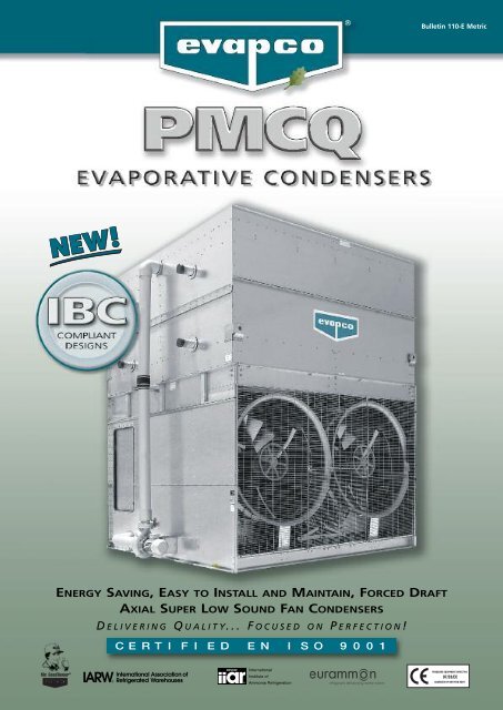
F U T U R E , A V A I L A B L E T O D A Y !NEWImproved Water Distribution Piping• Horizontally mounted pumps allow forreduced basin water level*• Simplified piping for easier basin access• Totally enclosed pump motors assure long,trouble-free life* Refer to engineering data for availabilityDESIGN AND CONSTRUCTION FEATURES<strong>EVAPCO</strong> is proud to introduce the latest in evaporative condenser technology,the <strong>PMCQ</strong>. This Evaporative Condenser features Quiet Super Low SoundTechnology and is Easy to install, Easy to maintain and Energy Saving!NEWSloped Pan Bottom• Pan bottom slopes to drain• Easy to clean• Stainless steel strainerresists corrosionWater Saver Drift Eliminators• New patented design reduces driftrate to 0.001%• Saves water and reduces watertreatment cost• Greater structural integrity vs. oldstyle blade-type• Recessed into casing for greaterprotection• Drift rate certifications as perEurovent OM-14-2009Double-Breake Flange Joints• Stronger than single-brake designsby others• Minimizes water leaks at field joints• Greater structural integrityNEWUnique Field Seam• Eliminates up to 85% of fasteners• Self guiding channels improve qualityof field seam to eliminate leaks• Easy to install• Lower installation costNEWIndividual Fan DriveSystem - STANDARD• Increased flexibility for improvedcapacity control• Greater reliability throughredundancy• Easy motor replacement• Front mounted drives for improvedmaintenance accessibility3DESIGN MAINTENANCE OPTIONS SOUNDI B C ENGINEERING SPECIFICATIONS
D E S I G NF E A T U R E SProven Performance & Design FlexibilityThe new <strong>PMCQ</strong> Evaporative Condenser offers more capacity andgreater system design flexibility than ever before. <strong>EVAPCO</strong>'s researchand development team has invested hundreds of hours in laboratorytesting to develop the next generation in Forced Draft CondenserTechnology. These efforts have produced a totally new fan sectiondesign which is now combined with the proven Thermal-Pak II ® coiltechnology to offer improved condenser performance.The <strong>PMCQ</strong> features more plan area options and fan horsepoweroptions for the system design engineer. With more condensercapacity, more plan area options and greater flexibility in motorselection, the design engineer can now match the condenserperformance to the specific application requirements. Moreequipment choices and more design flexibility mean greater value forthe End-User.Patented Thermal-Pak II ® Coil DesignLower Refrigerant ChargeOnly <strong>EVAPCO</strong> condensers offer the patented* Thermal-Pak II ® Coil which assuresgreater operating efficiency in your condenser. Its unique elliptical tube designallows for closer tube spacing resulting in more surface area per plan area thantraditional round tube designs. The Thermal-Pak II ® Coil design has lowerresistance to air flow and permits greater water loading, making the Thermal-Pak II ® Coil the most efficient design available. And now with its new tubecircuiting and orientation pattern, the Thermal-Pak II ® coil yields a lowerrefrigerant charge.*U.S. Patent No. 4755331Thermal-Pak ® II Coil by <strong>EVAPCO</strong>Energy Efficient for Lowest Operating CostRound Tube Coil by OthersLower Horsepower OptionsThe new fan drive system of the <strong>PMCQ</strong> utilizes larger diameter vane-axial fans in a two stage arrangement to providemore efficient air flow and reduced power consumption. When compared to the traditional centrifugal fan condensermodels, the vane-axial fan design can offer up to a 50% reduction in energy consumption. And, with the new <strong>PMCQ</strong>model selections even more low horsepower options are available to obtain greater energy savings.Individual Fan Drive SystemCapacity Control Flexibility & Operating RedundancyThe new <strong>PMCQ</strong> fan drive system provides individualmotor to fan configuration as standard equipment onall models. The dedicated fan to motor arrangementensures less “wear & tear” on the drive system versustandem fan motor drive arrangements resulting in lessmaintenance. The individual motor to fan designoffers greater capacity control flexibility to match thesystem load requirements. In addition, all Evapcocondensers are equipped with an internal bafflesystem which extends from the pan bottom verticallythrough the coil bundle. This unique design allowsthe user to cycle fan motors independently withoutharmful effects of air by-pass inside the unit. Theindividual motor to fan design ensures maximum operating redundancy in the condenser fan system when criticaloperation is necessary.DESIGN4
M A I N T E N A N C EA D V A N T A G E SImproved MaintenanceOversized Access DoorFor enhanced basin accessibility, the Oversized Access Door optionenables maintenance personnel to quickly and easily enter the basinfor float valve adjustment and unit inspection, cleaning andmaintenance.Fan Drive AccessibilityThe drive components of the <strong>PMCQ</strong> are easily accessed for routinemaintenance from the front of the unit. Bearing grease fittings areextended to the outside of the unit for ease of lubrication. All drivesheaves have been relocated to the front of the fan section and motorsare positioned on a platform base to allow for easy belt tension adjustment.Easy Clean Sloped BasinThe <strong>PMCQ</strong> drain pan is designed to improve maintenance access and make it easier foroperating technicians to clean. The bottom of the pan is sloped to the unit drain toensure that the basin will completely drain and allow sediment and debris that maycollect in the basin to be easily flushed from the unit. The design helps to preventbuildup of sedimentary deposits, biological films and standing water.Pressurized Water Distribution SystemThe water distribution system is made of schedule 40 PVC pipe and ABS plasticwater diffusers for corrosion protection in this key area. The piping is easilyremovable for cleaning. The water diffusers have a large orifice and are practicallyimpossible to clog. They also have an anti-sludge ring extending into the headersto prevent sediment from building up in the diffuser opening. In addition, thespray branches have threaded end caps to allow easy debris removal.All <strong>PMCQ</strong> units have as per standard the ZM II Nozzle to ensure that every squaremeter of heat transfer surface receives complete and even water coverage, resultingin maximum thermal performance.ZM II NozzleClean Pan Basin DesignThe basin of the New <strong>PMCQ</strong> is sloped toward a depressed areawhere the drain is located. With the "Clean Pan" design, it is easyfor a service mechanic to flush the pan.Optionalaccess doorMAINTENANCEStainless Steel StrainersThe <strong>EVAPCO</strong> standard for many years, the stainless steel straineris one component that is subject to excessive wear and corrosion.With stainless steel construction, this component will last the lifeof the unit.6
O P T I O N A LE Q U I P M E N TTwo Speed MotorsTwo speed fan motors can provide an excellent meansof capacity control. In periods of lightened loads orreduced wet bulb temperatures, the fans can operateat low speed, which will provide about 60% of fullspeed capacity, yet consume only about 15% of thepower compared with high speed. In addition to theenergy savings, the sound levels of the units will begreatly reduced at low speed.Inverter Duty Fan MotorsInverter Duty Fan Motors are available for condenserapplications which utilize variable frequency drivesystems for capacity control. Inverter Duty Fan Motorsoffer totally enclosed premium efficiency constructionwhich is designed for variable frequency driveapplications.Note: Other special motor configurations are availableto meet specific proper requirements. Contact yourlocal <strong>EVAPCO</strong> sales representative for applicationassistance and motor availability.Remote Sump ConfigurationFor units operating in areas where temperatures maybe very low, or where low temperatures may occurduring periods when the unit is not operating, a sumplocated inside the building is the preferred means ofensuring that the basin water will not freeze. For theseapplications, the condenser will be supplied withoutthe spray pump, suction strainers and all associatedpiping, but with an oversize bottom outlet.Electric Water Level ControlEvaporative condensers may be ordered with anelectric water level control in lieu of the standardmechanical float and make-up assembly. This packageprovides accurate control of water levels and does notrequire field adjustment.Multiple Circuit CoilsCondensers may be supplied with multiple circuit coilsto match various system requirements such as splitsystems, or if a glycol or water circuit is desired forcompressor head cooling.Basin Heater PackageIf a remote sump configuration is not practical, electricbasin heater packages are available to help preventfreeze-up of the basin water. The packages includeelectric heater elements, and a combinationthermostat/low water cutoff.Note: External pumps should be heat traced andinsulated in the field to prevent freezing.Electric HeatersElectric immersion heaters are available factoryinstalled in the basin of the condenser. They are sizedto maintain a +5°C pan water temperature with thefans off and an ambient air temperature of -18°C.They are furnished with a combination thermostat/lowwater protection device to cycle the heater on whenrequired and to prevent the heater elements fromenergizing unless they are completely submerged.All components are in weather proof enclosures foroutdoor use. The heater power contactors and electricwiring are not included as standard.Models<strong>PMCQ</strong> Heater Power<strong>PMCQ</strong>-316 to <strong>PMCQ</strong>-493 8kW<strong>PMCQ</strong>-476 to <strong>PMCQ</strong>-740 12<strong>PMCQ</strong>-734 to <strong>PMCQ</strong>-986 16<strong>PMCQ</strong>-952 to <strong>PMCQ</strong>-1480 24<strong>PMCQ</strong>-399 to <strong>PMCQ</strong>-561 10<strong>PMCQ</strong>-603 to <strong>PMCQ</strong>-845 14<strong>PMCQ</strong>-765 to <strong>PMCQ</strong>-893 16<strong>PMCQ</strong>-798 to <strong>PMCQ</strong>-1122 18<strong>PMCQ</strong>-1206 to <strong>PMCQ</strong>-1690 30<strong>PMCQ</strong>-1618 & <strong>PMCQ</strong>-1786 30OPTIONS7
O P T I O N A LE Q U I P M E N TSteel SupportThe recommended support for <strong>EVAPCO</strong> condensers isstructural “I” beams located under the outer flanges andrunning the entire length of the unit. Mounting holes,19 mm in diameter are located in the bottom channels ofthe pan section to provide for bolting to the structuralsteel. (Refer to certified drawings from the factory forbolt hole locations.)Beams should be level to within 3 mm in 1,8 m beforesetting the unit in place. Do not level the unit byshimming between it and the “I” beams as this will notprovide proper longitudinal support.<strong>PMCQ</strong> Dimensions (mm)3 m Wide Models A B<strong>PMCQ</strong>-316 to <strong>PMCQ</strong>-493 3651 2990<strong>PMCQ</strong>-476 to <strong>PMCQ</strong>-740 5490 2990<strong>PMCQ</strong>-734 to <strong>PMCQ</strong>-986 7337 2990<strong>PMCQ</strong>-952 to <strong>PMCQ</strong>-1480 <strong>110</strong>24 29903,6 m Wide Models A B<strong>PMCQ</strong>-399 to <strong>PMCQ</strong>-561 3651 3616<strong>PMCQ</strong>-603 to <strong>PMCQ</strong>-845 5490 3616<strong>PMCQ</strong>-765 to <strong>PMCQ</strong>-893 6102 3616<strong>PMCQ</strong>-798 to <strong>PMCQ</strong>-1122 7337 3616<strong>PMCQ</strong>-1206 to <strong>PMCQ</strong>-1690 <strong>110</strong>24 3616<strong>PMCQ</strong>-1618 & <strong>PMCQ</strong>-1786 12243 3616ABOPTIONS8
Super LowSound Technologyon EvaporativeCondensersPMCA Condenseris now available withSuper Low Sound fansto reduce the overallsound andimprove theenergySOUNDconsumptionby 50%compared toconventionalcentrifugal fancondensers.Ultra Quietoperation for ForcedDraft CounterflowEvaporativeCondensers9
Solutions for Saving Energy and Sound Sensitive ApplicationsS U P E R L O W S O U N DF A N T E C H N O L O G YThe NEW <strong>PMCQ</strong> Condenser comes standard with Super Low Sound Fans. They reduce the overall sound generationcompared to forced draft centrifugal condensers, and additionally reduce the energy consumption by 50%.Consult <strong>EVAPCO</strong>'s selection software for unit sound levels. If a detailed analysis or full octave band datasheet is requiredfor your application, please consult your <strong>EVAPCO</strong> Sales Representative.SOUNDReduced Sound Levels and Reduced Energy Consumption versus Centrifugal Fan Units<strong>EVAPCO</strong>'s Super Low Sound Fan on the <strong>PMCQ</strong> condensers utilizes an extremely wide chord blade design available forsound sensitive applications where the lowest sound levels are desired. The fan is one piece molded heavy duty FRPconstruction utilizing a forward swept blade design.Improved Sound Quality versusstandard straight bladed axial fan typesThe SUPER Low Sound Fan on the <strong>PMCQ</strong> condensers reducessound levels 10 to 13 dB(A) and eliminates audible bladepassing frequencies indicative of straight bladed axial type fans.Refer to the Narrow Band Spectrum graph which shows howstraight bladed axial fans produce blade passing frequencies –the same phenomena that produce the signature pulsatinghelicopter noise.The blade passing frequencies are audible spikes in soundpressure levels, but are not apparent in the octave band soundspectrum.<strong>PMCQ</strong> / LSCB Sound ComparisonsSound Pressure LevelsFanOpp.Motor Fan Opp. FanModel No. Power End Side End Side TopLSCB-400 22 58 66 57 56 63<strong>PMCQ</strong>-405 11 57 66 57 57 62LSCB-625 37 59 66 59 56 63<strong>PMCQ</strong>-613 22 59 69 59 58 63NOTE: Sound pressure levels in dBA 15 m from source• Reduced energy consumption compared to Forced DraftCentrifugal Condensers• Typical sound values equal or lower than Forced DraftCentrifugal Condensers of similar sizeThe Super Low Sound Fan on the <strong>PMCQ</strong> Condenser reduces soundlevels and fan power without compromizing the sound quality!Blade Passing FrequenciesSound Pressure Level (dB)Standard Axial Fan Forced DraftSuper Low Sound Fan Forced DraftFrequency (Hz)Narrow Band Spectrum Analysis10
We Stand TallThrough it All!The InternationalBuilding Code (IBC) is acomprehensive set ofregulations addressingthe structural designand installationrequirements forbuilding systems–including HVACand industrialrefrigerationequipment.I B CWith the adventof the IBC,<strong>EVAPCO</strong> isproud tointroduce the new andimproved line of <strong>PMCQ</strong>Condensers with IBC 2006compliance standard.Wind, Rain,Earthquakeand Hurricane<strong>EVAPCO</strong> Condensers… designed towithstand seismic or wind load forces.11
I B C C E R T I F I C A T I O NIn its continuing commitment to be the leaders in evaporative cooling equipmentdesign and services, <strong>EVAPCO</strong> <strong>PMCQ</strong> Condensers are now Independently Certified to withstandSeismic and Wind Loads in accordance with IBC 2006.I B CWhat is IBC?International Building CodeThe International Building Code (IBC) is a comprehensive set ofregulations addressing both the structural design and theinstallation requirements for building systems – including HVACand industrial refrigeration equipment.Compared to previous building codes that considered only thebuilding structure and component anchorage, the requirementscontained within the IBC address anchorage, structural integrity,and the operational capability of a component following eithera seismic or wind load event. Simply stated, the IBC codeprovisions require that evaporative cooling equipment, and allother components permanently installed on a structure, mustbe designed to meet the same seismic or wind load forces asthe building to which they are attached.exhaustive analysis by an independent approval agency. Asrequired by the International Building Code, <strong>EVAPCO</strong> supplies acertificate of compliance as part of its submittal documents. Thecertificate of compliance demonstrates that the equipment hasbeen independently tested and analyzed in accordance with theIBC seismic and wind load requirements. Evapco has workedclosely with the independent approval agency, The VMC Group,to complete the independent equipment testing and analysis.If the seismic “g force” or wind load requirements for theproject site are known, <strong>EVAPCO</strong>’s online equipment selectionsoftware, iES, will allow you to choose the required structuraldesign package – either standard construction or upgradedconstruction.For further questions regarding IBC compliance, please contactyour local <strong>EVAPCO</strong> Representative.How Does IBC 2006 Apply to Condenser?Based on site design factors, calculations are made to determinethe equivalent seismic “g force” and wind load (kilo-Newton persquare meter, kN/m 2 ) on the unit. The cooling tower must bedesigned to withstand the greater of either the seismic or windload.All locations with design criteria resulting in a seismic designforce of up to 1.0g or a wind load of 2,87 kN/m 2 or below willbe provided with the standard <strong>PMCQ</strong> structural design. Anupgraded structural design is available for installations withdesign criteria resulting in “g forces” greater than 1.0g. Thehighest “g force” location in North America is 5.12g. Thehighest wind load shown on the maps is 273 km/h, which isapproximately equal to 6,94 kN/m 2 velocity pressure.Therefore, the upgraded structural design package option forthe New <strong>PMCQ</strong> is designed for 5.12 g and 6,94 kN/m 2 makingit applicable to most building locations all over the World.Design Implementation<strong>EVAPCO</strong> applies the seismic design and wind load informationprovided for the project to determine the equipment designnecessary to meet IBC requirements. This process ensures thatthe mechanical equipment and its components are compliantper the provisions of the IBC as given in the plans andspecifications for the project.Independent CertificationAlthough the IBC references and is based on the structuralbuilding code ASCE 7, many chapters and paragraphs of ASCE 7are superceded by the IBC, independent certification andmethods of analysis are such paragraphs. Per the most recentedition of the code, the <strong>EVAPCO</strong> compliance process included an12
EngineeringDataENGINEERINGDimensions13
E N G I N E E R I N G D ATA & D I M E N S I O N SENGINEERINGPrinciple of OperationThe refrigerant gas is discharged from the compressor intothe inlet connection of the evaporative condenser. Waterfrom the condenser’s sump is continuously flooded overthe condenser coil, while ambient air is simultaneouslyforced into the unit. As the ambient air moves up throughthe coil section, a portion of the spray water is evaporatedinto the air stream.The evaporative process cools the spray water, which inturn cools the tubes containing the refrigerant gas. Thecool tube walls cause the refrigerant gas to give up heatand condense into a liquid. The condensed liquid flowsout of the coil’s sloping tubes to the high pressure liquidreceiver for return to the system.The hot, saturated air is driven through the drifteliminators, where any entrained water droplets areremoved. The condenser’s fan then discharges this airstream out of the top of the unit at a high velocity, whereit can dissipate harmlessly into the atmosphere. The waterwhich was not evaporated falls into the sump and isrecirculated by the spray pump to the water distributionsystem above the condensing coil section.SuperheatedRefrigerantGas InCondensedRefrigerantLiquid OutCool DryEntering AirHot SaturatedDischarge AirPrinciple of OperationSelection ProcedureTwo methods of selection are presented, the first is basedon the total heat of rejection as described immediatelybelow. The second and more simple method is based onevaporator tons. The evaporator ton method is onlyapplicable to systems with open type reciprocatingcompressors.The heat of rejection method is applicable to all butcentrifugal compressor applications and is normally usedfor selecting evaporative condensers for use with hermeticcompressors and screw compressors. It can also be used forstandard open type reciprocating compressors as analternate to the evaporator ton method.The evaporator ton method is based on the estimated heatof compression. The heat of rejection method of selectionis more accurate and should be used whenever possible.Refer to the factory for selections on systems withcentrifugal compressors.Heat of Rejection MethodIn the heat of rejection method, a factor for the specifiedoperating conditions (condensing temperature and wet bulb)is obtained from Table 1 or 2 and multiplied times the heat ofrejection.The resultant figure is used to select a unit from Table 3.Unit capacities are given in Table 3 in kW.If the heat of rejection is not known, it can be determined byone of the following formulas:Open Compressors:Heat of Rejection = Evaporator Load (kW) + Compressor kWHermetic Compressors:Heat of Rejection = Evaporator Load (kW) + CompressorInput kWEXAMPLEGiven:1000 kW evaporator load, ammonia refrigerant36°C condensing temperature, 26°C wet bulbtemperature with a 300 kW compressor.Selection: Evaporator Load = 1000 kWCompressor Load = 300 kWTotal = 1300 kWHeat of RejectionFrom Table 2, the capacity factor for 36°C condensingtemperature and 26°C wet bulb temperature = 1.391300 1.39 1807(Total Heat x (Capacity = (Corrected Heatof Rejection) Factor) Rejection Load)Therefore, select <strong>PMCQ</strong>-434Note: For screw compressor selections employing watercooled oil cooling, select a condenser for the total kW asin the example. The condenser can then function in oneof two ways:(1) Recirculating water from the water sump can beused directly in the oil cooler. A separate pump shouldbe employed and the return water should be directedinto the water sump at the opposite end from thepump suction.(2) The condenser coil can be circuited so that water ora glycol-water mixture for the oil cooler can be cooledin a separate section of the coil. Specify load andwater flow required.For refrigerant injection cooled screw compressors, selectthe condenser in the same manner as shown in theexample.If the oil cooler is supplied by water from a separatesource, then the oil cooling load should be deducted fromthe heat of rejection before making the selection.14
E N G I N E E R I N G D ATA & D I M E N S I O N SSELECTION PROCEDURETable 1 - HCFC-22 and HFC-134a Heat Rejection FactorsCondensingPres. psigCond.Wet Bulb Temperature, (°C)Temp.HCFC- HFC-22 134a °C10 12 14 16 17 18 19 20 21 22 23 24 25 26 27 28 29 301090 669 30 1,07 1,15 1,25 1,38 1,47 1,57 1,69 1,83 2,00 2,23 2,50 2,86 3,36 –– –1154 718 32 0,94 1,01 1,09 1,19 1,26 1,32 1,40 1,49 1,60 1,74 1,90 2,11 2,36 – – – – –1220 759 34 0,85 0,90 0,97 1,04 1,09 1,14 1,20 1,26 1,34 1,43 1,54 1,66 1,81 2,02 2,31 – – –1253 785 35 0,80 0,85 0,91 0,97 1,02 1,06 1,11 1,15 1,21 1,29 1,37 1,46 1,56 1,71 1,89 2,13 2,41 2,771287 814 36 0,77 0,81 0,86 0,92 0,96 1,00 1,04 1,07 1,13 1,19 1,26 1,34 1,43 1,56 1,71 1,90 2,14 2,431359 856 38 0,70 0,74 0,78 0,82 0,85 0,86 0,90 0,93 0,96 1,01 1,06 1,11 1,18 1,26 1,35 1,47 1,62 1,781431 915 40 0,65 0,67 0,70 0,73 0,76 0,78 0,80 0,83 0,86 0,89 0,93 0,97 1,02 1,08 1,14 1,22 1,32 1,441508 978 42 0,59 0,62 0,64 0,67 0,68 0,70 0,72 0,74 0,77 0,80 0,83 0,86 0,89 0,94 0,98 1,04 1,11 1,191587 1026 44 0,54 0,56 0,59 0,61 0,62 0,63 0,65 0,66 0,68 0,70 0,73 0,75 0,78 0,82 0,85 0,89 0,92 0,97Note: Consult factory for selections using other refrigerants.ENGINEERINGTable 2 - Ammonia (R-717) Heat Rejection FactorsCondensing Cond.Pres.Wet Bulb Temperature, (°C)Temp.(kPa)°C10 12 14 16 17 18 19 20 21 22 23 24 25 26 27 28 29 301063 30 0,95 1,03 1,12 1,23 1,31 1,40 1,51 1,63 1,79 1,99 2,24 2,56 3,00 – – – – –1133 32 0,84 0,90 0,97 1,06 1,12 1,18 1,25 1,32 1,43 1,55 1,70 1,88 2,11 – – – – –1206 34 0,76 0,81 0,86 0,93 0,98 1,02 1,07 1,12 1,19 1,28 1,36 1,48 1,61 1,80 2,06 – – –1245 35 0,71 0,76 0,81 0,87 0,91 0,95 0,99 1,03 1,08 1,15 1,23 1,30 1,39 1,53 1,69 1,90 2,15 2,471284 36 0,69 0,73 0,77 0,82 0,86 0,89 0,92 0,96 1,01 1,07 1,13 1,20 1,28 1,39 1,53 1,70 1,91 2,171365 38 0,63 0,66 0,69 0,73 0,76 0,78 0,81 0,83 0,86 0,90 0,94 0,99 1,05 1,12 1,21 1,31 1,44 1,591451 40 0,58 0,60 0,62 0,65 0,67 0,70 0,72 0,74 0,76 0,80 0,83 0,87 0,91 0,96 1,02 1,09 1,18 1,291539 42 0,53 0,55 0,57 0,60 0,61 0,63 0,64 0,66 0,68 0,71 0,74 0,76 0,80 0,84 0,88 0,93 0,99 1,061630 44 0,49 0,50 0,52 0,54 0,56 0,56 0,58 0,59 0,61 0,63 0,65 0,67 0,70 0,73 0,76 0,79 0,83 0,86Table 3 - Unit Heat RejectionModelkW BaseModel kW Base Model kW Base Model kW Base Model kW BaseModelkW Base<strong>PMCQ</strong>-316 1361<strong>PMCQ</strong>-530 2283<strong>PMCQ</strong>-842 3627<strong>PMCQ</strong>-1480 6376<strong>PMCQ</strong>-761 3279<strong>PMCQ</strong>-1070 4610<strong>PMCQ</strong>-350 1508<strong>PMCQ</strong>-566 2438<strong>PMCQ</strong>-882 3800<strong>PMCQ</strong>-399 1719<strong>PMCQ</strong>-815 3511<strong>PMCQ</strong>-1122 4834<strong>PMCQ</strong>-367 1581<strong>PMCQ</strong>-575 2477<strong>PMCQ</strong>-916 3946<strong>PMCQ</strong>-427 1840<strong>PMCQ</strong>-845 3641<strong>PMCQ</strong>-1206 5196<strong>PMCQ</strong>-379 1633<strong>PMCQ</strong>-604 2602<strong>PMCQ</strong>-934 4024<strong>PMCQ</strong>-463 1995<strong>PMCQ</strong>-765 3296<strong>PMCQ</strong>-1288 5549<strong>PMCQ</strong>-380 1637<strong>PMCQ</strong>-613 2641<strong>PMCQ</strong>-986 4248<strong>PMCQ</strong>-469 2020<strong>PMCQ</strong>-809 3485<strong>PMCQ</strong>-1308 5635<strong>PMCQ</strong>-405 1745<strong>PMCQ</strong>-655 2822<strong>PMCQ</strong>-952 4101<strong>PMCQ</strong>-510 2197<strong>PMCQ</strong>-850 3662<strong>PMCQ</strong>-1374 5919<strong>PMCQ</strong>-407 1753<strong>PMCQ</strong>-656 2826<strong>PMCQ</strong>-1034 4455<strong>PMCQ</strong>-535 2305<strong>PMCQ</strong>-893 3847<strong>PMCQ</strong>-1402 6040<strong>PMCQ</strong>-410 1766<strong>PMCQ</strong>-683 2942<strong>PMCQ</strong>-1060 4567<strong>PMCQ</strong>-561 2417<strong>PMCQ</strong>-798 3438<strong>PMCQ</strong>-1472 6341<strong>PMCQ</strong>-434 1870<strong>PMCQ</strong>-694 2990<strong>PMCQ</strong>-1132 4877<strong>PMCQ</strong>-603 2598<strong>PMCQ</strong>-854 3679<strong>PMCQ</strong>-1522 6557<strong>PMCQ</strong>-441 1900<strong>PMCQ</strong>-740 3188<strong>PMCQ</strong>-1150 4954<strong>PMCQ</strong>-644 2775<strong>PMCQ</strong>-908 3912<strong>PMCQ</strong>-1550 6678<strong>PMCQ</strong>-458 1973<strong>PMCQ</strong>-734 3162<strong>PMCQ</strong>-1212 5221<strong>PMCQ</strong>-654 2818<strong>PMCQ</strong>-926 3989<strong>PMCQ</strong>-1630 7022<strong>PMCQ</strong>-467 2012<strong>PMCQ</strong>-760 3274<strong>PMCQ</strong>-1226 5282<strong>PMCQ</strong>-687 2960<strong>PMCQ</strong>-938 4041<strong>PMCQ</strong>-1690 7281<strong>PMCQ</strong>-493 2124<strong>PMCQ</strong>-810 3490<strong>PMCQ</strong>-1312 5652<strong>PMCQ</strong>-701 3020<strong>PMCQ</strong>-972 4187<strong>PMCQ</strong>-1618 6971<strong>PMCQ</strong>-476 2051<strong>PMCQ</strong>-820 3533<strong>PMCQ</strong>-1366 5885<strong>PMCQ</strong>-736 3171<strong>PMCQ</strong>-1020 4394<strong>PMCQ</strong>-1786 769415
E N G I N E E R I N G D ATA & D I M E N S I O N SMODELS <strong>PMCQ</strong> 316 THRU 7407721448ENGINEERINGUOVERSIZEDACCESSDOORS(2) 100 BFW REFRIG. IN(2) 100 BFW REFRIG. OUT50 MPTMAKE UP2623E3022H<strong>PMCQ</strong> 316 thru 493 <strong>PMCQ</strong> 476 thru 74080 MPTDRAIN80 FPTOVERFLOW2991457 3652 524 5490Table 4 Engineering DataFans Weights (kg) NH 3 Spray Pump Remote Sump Dimensions (mm)Operating CoilModel Motor Air Flow Heaviest Charge Volume Liters Conn. Operating Height Upper Coil DistanceNo. (kW) (m 3 /s) Shipping Operating Section† (kg)** (l) (kW) (l/s) Req’d* Size Weight (kg) H U E<strong>PMCQ</strong>-316 (2) 4 26 6.055 7.905 3.895 (C) 115 963 4,0 43,2 14158 250 7.600 4150 1549 565<strong>PMCQ</strong>-350 (2) 5.5 29 6.105 7.955 3.895 (C) 115 963 4,0 43,2 14158 250 7.650 4150 1549 565<strong>PMCQ</strong>-367 (2) 4 25 7.795 9.715 5.635 (C) 185 1557 4,0 43,2 14158 250 9.410 4582 1981 997<strong>PMCQ</strong>-379 (2) 7.5 32 6.120 7.970 3.895 (C) 115 963 4,0 43,2 14158 250 7.660 4150 1549 565<strong>PMCQ</strong>-380 (2) 5.5 29 7.000 8.885 4.790 (C) 145 1246 4,0 43,2 14158 250 8.575 4366 1765 781<strong>PMCQ</strong>-405 (2) 5.5 29 7.845 9.765 5.635 (C) 185 1557 4,0 43,2 14158 250 9.455 4582 1981 997<strong>PMCQ</strong>-407 (2) 11 37 6.235 8.090 3.895 (C) 115 963 4,0 43,2 14158 250 7.780 4150 1549 565<strong>PMCQ</strong>-410 (2) 7.5 32 7.015 8.900 4.790 (C) 145 1246 4,0 43,2 14158 250 8.590 4366 1765 781<strong>PMCQ</strong>-434 (2) 7.5 32 7.855 9.780 5.635 (C) 185 1557 4,0 43,2 14158 250 9.470 4582 1981 997<strong>PMCQ</strong>-441 (2) 11 37 7.130 9.015 4.790 (C) 145 1246 4,0 43,2 14158 250 8.710 4366 1765 781<strong>PMCQ</strong>-458 (2) 7.5 31 8.740 10.695 6.520 (C) 220 1869 4,0 43,2 14158 250 10.385 4797 2197 1213<strong>PMCQ</strong>-467 (2) 11 36 7.975 9.895 5.635 (C) 185 1557 4,0 43,2 14158 250 9.590 4582 1981 997<strong>PMCQ</strong>-493 (2) 11 36 8.860 10.815 6.520 (C) 220 1869 4,0 43,2 14158 250 10.505 4797 2197 1213<strong>PMCQ</strong>-476 (3) 4 39 9.215 12.085 5.705 (C) 165 1416 5,5 65 17556 300 11.085 4150 1549 565<strong>PMCQ</strong>-530 (3) 5.5 44 9.290 12.155 5.705 (C) 165 1416 5,5 65 17556 300 11.160 4150 1549 565<strong>PMCQ</strong>-566 (3) 7.5 49 9.310 12.180 5.705 (C) 165 1416 5,5 65 17556 300 11.180 4150 1549 565<strong>PMCQ</strong>-575 (3) 5.5 44 10.620 13.540 7.035 (C) 220 1869 5,5 65 17556 300 12.540 4366 1765 781<strong>PMCQ</strong>-604 (3) 11 56 9.490 12.355 5.705 (C) 165 1416 5,5 65 17556 300 11.360 4150 1549 565<strong>PMCQ</strong>-613 (3) 7.5 48 10.640 13.560 7.035 (C) 220 1869 5,5 65 17556 300 12.565 4366 1765 781<strong>PMCQ</strong>-655 (3) 11 55 10.820 13.740 7.035 (C) 220 1869 5,5 65 17556 300 12.740 4366 1765 781<strong>PMCQ</strong>-656 (3) 7.5 47 11.920 14.890 8.315 (C) 270 2322 5,5 65 17556 300 13.895 4582 1981 997<strong>PMCQ</strong>-683 (3) 7.5 47 13.250 16.275 9.645 (C) 325 2775 5,5 65 17556 300 15.275 4797 2197 1213<strong>PMCQ</strong>-694 (3) 11 54 12.095 15.070 8.315 (C) 270 2322 5,5 65 17556 300 14.070 4582 1981 997<strong>PMCQ</strong>-740 (3) 11 54 13.425 16.450 9.645 (C) 325 2775 5,5 65 17556 300 15.455 4797 2197 1213† (C) = Casing (P) = Pan* Liters shown is water in suspension in unit and piping. Allow for additional water in bottom of remote sump to cover pump suction and strainer during operation.(300 mm would normally be sufficient.)** Refrigerant charge is shown for R-717. Multiply by 1.93 for R-22 and 1.98 for R-134a. Dimensions are subject to change. Do not use for pre-fabrication.16
E N G I N E E R I N G D ATA & D I M E N S I O N SMODELS <strong>PMCQ</strong> 734 THRU 14807721448UOVERSIZEDACCESSDOORS80 MPTDRAIN(4) 100 BFW REFRIG. IN(4) 100 BFW REFRIG. OUT50 MPTMAKE UP80 FPTOVERFLOW2623E3022H<strong>PMCQ</strong> 734 thru 986ENGINEERING2991457 7339 416<strong>PMCQ</strong> 952 thru 1480524 <strong>110</strong>24 600Table 5 Engineering DataFans Weights (kg) NH 3 Spray Pump Remote Sump Dimensions (mm)Operating CoilModel Motor Air Flow Heaviest Charge Volume Liters Conn. Operating Height Upper Coil DistanceNo. (kW) (m 3 /s) Shipping Operating Section† (kg)** (l) (kW) (l/s) Req’d* Size Weight (kg) H U E<strong>PMCQ</strong>-734 (4) 4 50 15.800 19.810 5590 (C) 365 3115 (2) 4 86,4 26335 300 18.840 4582 1981 997<strong>PMCQ</strong>-760 (4) 5.5 58 14.115 18.055 4715 (P) 295 2520 (2) 4 86,4 26335 300 17.080 4366 1765 781<strong>PMCQ</strong>-810 (4) 5.5 57 15.895 19.905 5590 (C) 365 3115 (2) 4 86,4 26335 300 18.935 4582 1981 997<strong>PMCQ</strong>-820 (4) 7.5 64 14.145 18.080 4745 (P) 295 2520 (2) 4 86,4 26335 300 17.<strong>110</strong> 4366 1765 781<strong>PMCQ</strong>-842 (4) 5.5 56 17.755 21.830 6520 (C) 435 3710 (2) 4 86,4 26335 300 20.860 4797 2197 1213<strong>PMCQ</strong>-882 (4) 11 73 14.385 18.320 4985 (P) 295 2520 (2) 4 86,4 26335 300 17.350 4366 1765 781<strong>PMCQ</strong>-916 (4) 7.5 62 17.780 21.860 6520 (C) 435 3710 (2) 4 86,4 26335 300 20.890 4797 2197 1213<strong>PMCQ</strong>-934 (4) 11 72 16.160 20.170 5590 (C) 365 3115 (2) 4 86,4 26335 300 19.200 4582 1981 997<strong>PMCQ</strong>-986 (4) 11 71 18.020 22.100 6520 (C) 435 3710 (2) 4 86,4 26335 300 21.130 4797 2197 1213<strong>PMCQ</strong>-952 (6) 4 77 17.755 23.635 6685 (P) 335 2832 (2) 5.5 130 39644 350 22.150 4150 1549 565<strong>PMCQ</strong>-1034 (6) 4 76 20.530 26.515 6920 (C) 440 3738 (2) 5.5 130 39644 350 25.035 4366 1765 781<strong>PMCQ</strong>-1060 (6) 5.5 88 17.895 23.775 6825 (P) 335 2832 (2) 5.5 130 39644 350 22.290 4150 1549 565<strong>PMCQ</strong>-1132 (6) 7.5 98 17.940 23.825 6870 (P) 335 2832 (2) 5.5 130 39644 350 22.335 4150 1549 565<strong>PMCQ</strong>-1150 (6) 5.5 87 20.670 26.660 6920 (C) 440 3738 (2) 5.5 130 39644 350 25.175 4366 1765 781<strong>PMCQ</strong>-1212 (6) 5.5 86 23.345 29.445 8260 (C) 545 4644 (2) 5.5 130 39644 350 27.955 4582 1981 997<strong>PMCQ</strong>-1226 (6) 7.5 96 20.715 26.705 6920 (C) 440 3738 (2) 5.5 130 39644 350 25.220 4366 1765 781<strong>PMCQ</strong>-1312 (6) 7.5 95 23.390 29.490 8260 (C) 545 4644 (2) 5.5 130 39644 350 28.000 4582 1981 997<strong>PMCQ</strong>-1366 (6) 7.5 93 26.160 32.360 9645 (C) 650 5550 (2) 5.5 130 39644 350 30.870 4797 2197 1213<strong>PMCQ</strong>-1480 (6) 11 107 26.510 32.715 9645 (C) 650 5550 (2) 5.5 130 39644 350 31.225 4797 2197 1213† (C) = Casing (P) = Pan* Liters shown is water in suspension in unit and piping. Allow for additional water in bottom of remote sump to cover pump suction and strainer during operation.(300 mm would normally be sufficient.)** Refrigerant charge is shown for R-717. Multiply by 1.93 for R-22 and 1.98 for R-134a. Dimensions are subject to change. Do not use for pre-fabrication.17
E N G I N E E R I N G D ATA & D I M E N S I O N SMODELS <strong>PMCQ</strong> 399 THRU 8459331743ENGINEERINGUOVERSIZEDACCESSDOORS(2) 100 BFW REFRIG. IN(2) 100 BFW REFRIG. OUT50 MPTMAKE UP2634E3023H<strong>PMCQ</strong> 399 thru 56180 MPTDRAIN80 FPTOVERFLOW3618457 3652<strong>PMCQ</strong> 603 thru 845524 5490Table 6 Engineering DataFans Weights (kg) NH 3 Spray Pump Remote Sump Dimensions (mm)Operating CoilModel Motor Air Flow Heaviest Charge Volume Liters Conn. Operating Height Upper Coil DistanceNo. (kW) (m 3 /s) Shipping Operating Section† (kg)** (l) (kW) (l/s) Req’d* Size Weight (kg) H U E<strong>PMCQ</strong>-399 (2) 5.5 35 7.050 9.335 4.520 (C) 140 1189 4,0 50,5 16141 250 8.870 4150 1549 565<strong>PMCQ</strong>-427 (2) 7.5 38 7.060 9.350 4.520 (C) 140 1189 4,0 50,5 16141 250 8.880 4150 1549 565<strong>PMCQ</strong>-463 (2) 7.5 37 8.145 10.480 5.605 (C) 180 1557 4,0 50,5 16141 250 10.010 4366 1765 781<strong>PMCQ</strong>-469 (2) 11 43 7.185 9.470 4.520 (C) 140 1189 4,0 50,5 16141 250 9.005 4150 1549 565<strong>PMCQ</strong>-510 (2) 11 42 8.270 10.600 5.605 (C) 180 1557 4,0 50,5 16141 250 10.135 4366 1765 781<strong>PMCQ</strong>-535 (2) 11 42 9.300 11.670 6.635 (C) 225 1926 4,0 50,5 16141 250 11.205 4582 1981 997<strong>PMCQ</strong>-561 (2) 11 41 10.310 12.730 7.650 (C) 270 2294 4,0 50,5 16141 250 12.260 4797 2197 1213<strong>PMCQ</strong>-603 (3) 5.5 53 10.725 14.050 6.770 (C) 205 1756 5,5 75,7 20954 300 12.845 4150 1549 565<strong>PMCQ</strong>-644 (3) 7.5 56 10.750 14.075 6.770 (C) 205 1756 5,5 75,7 20954 300 12.870 4150 1549 565<strong>PMCQ</strong>-654 (3) 5.5 52 12.345 15.740 8.385v 270 2294 5,5 75,7 20954 300 14.535 4366 1765 781<strong>PMCQ</strong>-687 (3) 5.5 51 13.905 17.365 9.945 (C) 335 2860 5,5 75,7 20954 300 16.155 4582 1981 997<strong>PMCQ</strong>-701 (3) 7.5 55 12.370 15.760 8.385 (C) 270 2294 5,5 75,7 20954 300 14.555 4366 1765 781<strong>PMCQ</strong>-736 (3) 7.5 54 13.930 17.385 9.945 (C) 335 2860 5,5 75,7 20954 300 16.180 4582 1981 997<strong>PMCQ</strong>-761 (3) 11 63 12.545 15.940 8.385 (C) 270 2294 5,5 75,7 20954 300 14.735 4366 1765 781<strong>PMCQ</strong>-815 (3) 11 63 14.105 17.565 9.945 (C) 335 2860 5,5 75,7 20954 300 16.355 4582 1981 997<strong>PMCQ</strong>-845 (3) 11 62 15.565 19.085 11.405 (C) 400 3426 5,5 75,7 20954 300 17.880 4797 2197 1213† (C) = Casing (P) = Pan* Liters shown is water in suspension in unit and piping. Allow for additional water in bottom of remote sump to cover pump suction and strainer during operation.(300 mm would normally be sufficient.)** Refrigerant charge is shown for R-717. Multiply by 1.93 for R-22 and 1.98 for R-134a. Dimensions are subject to change. Do not use for pre-fabrication.18
E N G I N E E R I N G D ATA & D I M E N S I O N SMODELS <strong>PMCQ</strong> 765 THRU 893MODELS <strong>PMCQ</strong> 798 THRU 1122933U1743(2) 100 BFW REFRIG. IN(2) 100 BFW REFRIG. OUTOVERSIZEDACCESSDOORS80 MPTMAKE UP2634E3022H<strong>PMCQ</strong> 765 thru 893ENGINEERING80 MPTDRAIN80 FPTOVERFLOW3618924 61039331743U(4) 100 BFW FLUID IN(4) 100 BFW FLUID OUTE<strong>PMCQ</strong> 798 thru 1122OVERSIZEDACCESSDOORS80 MPTMAKE UP 26343022H80 MPTDRAIN(2) 80 FPTOVERFLOW3618457 7339 416Table 7 Engineering DataFans Weights (kg) NH 3 Spray Pump Remote Sump Dimensions (mm)Operating CoilModel Motor Air Flow Heaviest Charge Volume Liters Conn. Operating Height Upper Coil DistanceNo. (kW) (m 3 /s) Shipping Operating Section† (kg)** (l) (kW) (l/s) Req’d* Size Weight (kg) H U E<strong>PMCQ</strong>-765 (3) 7.5 58 15.220 19.150 10.940 (C) 370 3171 7,5 88,3 22937 350 17.795 4582 1981 997<strong>PMCQ</strong>-809 (3) 7.5 57 17.065 21.070 12.785 (C) 445 3794 7,5 88,3 22937 350 19.715 4797 2197 1213<strong>PMCQ</strong>-850 (3) 11 66 15.395 19.330 10.940 (C) 370 3171 7,5 88,3 22937 350 17.970 4582 1981 997<strong>PMCQ</strong>-893 (3) 11 65 17.240 21.245 12.785 (C) 445 3794 7,5 88,3 22937 350 19.890 4797 2197 1213<strong>PMCQ</strong>-798 (4) 5.5 70 13.785 18.490 5.040 (P) 275 2350 (2) 4 100,9 30582 350 17.220 4150 1549 565<strong>PMCQ</strong>-854 (4) 7.5 75 13.810 18.515 5.065 (P) 275 2350 (2) 4 100,9 30582 350 17.245 4150 1549 565<strong>PMCQ</strong>-908 (4) 5.5 68 18.220 23.100 6.590 (C) 450 3823 (2) 4 100,9 30582 350 21.830 4582 1981 997<strong>PMCQ</strong>-926 (4) 7.5 74 16.090 20.885 5.510 (C) 365 3087 (2) 4 100,9 30582 350 19.615 4366 1765 781<strong>PMCQ</strong>-938 (4) 11 86 14.050 18.755 5.305 (P) 275 2350 (2) 4 100,9 30582 350 17.485 4150 1549 565<strong>PMCQ</strong>-972 (4) 7.5 73 18.250 23.130 6.590 (C) 450 3823 (2) 4 100,9 30582 350 21.860 4582 1981 997<strong>PMCQ</strong>-1020 (4) 11 85 16.330 21.125 5.510 (C) 365 3087 (2) 4 100,9 30582 350 19.855 4366 1765 781<strong>PMCQ</strong>-1070 (4) 11 84 18.490 23.370 6.590 (C) 450 3823 (2) 4 100,9 30582 350 22.100 4582 1981 997<strong>PMCQ</strong>-1122 (4) 11 82 20.600 25.570 7.650 (C) 540 4559 (2) 4 100,9 30582 350 24.300 4797 2197 1213† (C) = Casing (P) = Pan* Liters shown is water in suspension in unit and piping. Allow for additional water in bottom of remote sump to cover pump suction and strainer during operation.(300 mm would normally be sufficient.)** Refrigerant charge is shown for R-717. Multiply by 1.93 for R-22 and 1.98 for R-134a. Dimensions are subject to change. Do not use for pre-fabrication.19
E N G I N E E R I N G D ATA & D I M E N S I O N SMODELS <strong>PMCQ</strong> 1206 THRU 1786933 1743ENGINEERINGU80 MPTMAKE UPOVERSIZEDACCESS DOORS(4) 100 BFW REFRIG. IN(4) 100 BFW REFRIG. OUT2634E3023H<strong>PMCQ</strong> 1206 thru 169080 MPTDRAIN3618(2) 80 FPTOVERFLOW524<strong>110</strong>24600933 1743U80 MPTMAKE UPOVERSIZEDACCESS DOORS(4) 100 BFW REFRIG. IN(4) 100 BFW REFRIG. OUT2634E3023H<strong>PMCQ</strong> 1618 thru 1786(2) 80 MPTDRAIN3618(2) 80 FPTOVERFLOW924 83212243Table 8 Engineering DataFans Weights (kg) NH 3 Spray Pump Remote Sump Dimensions (mm)Operating CoilModel Motor Air Flow Heaviest Charge Volume Liters Conn. Operating Height Upper Coil DistanceNo. (kW) (m 3 /s) Shipping Operating Section† (kg)** (l) (kW) (l/s) Req’d* Size Weight (kg) H U E<strong>PMCQ</strong>-1206 (6) 5.5 105 20.515 27.505 7.355 (P) 410 3483 (2) 5.5 151,4 41343 400 24.945 4150 1549 565<strong>PMCQ</strong>-1288 (6) 7.5 112 20.555 27.545 7.395 (P) 410 3483 (2) 5.5 151,4 41343 400 24.985 4150 1549 565<strong>PMCQ</strong>-1308 (6) 5.5 104 23.875 30.995 8.260 (C) 540 4616 (2) 5.5 151,4 41343 400 28.430 4366 1765 781<strong>PMCQ</strong>-1374 (6) 5.5 102 27.120 34.375 9.885 (C) 670 5720 (2) 5.5 151,4 41343 400 31.805 4582 1981 997<strong>PMCQ</strong>-1402 (6) 7.5 <strong>110</strong> 23.915 31.035 8.260 (C) 540 4616 (2) 5.5 151,4 41343 400 28.470 4366 1765 781<strong>PMCQ</strong>-1472 (6) 7.5 109 27.160 34.415 9.885 (C) 670 5720 (2) 5.5 151,4 41343 400 31.845 4582 1981 997<strong>PMCQ</strong>-1522 (6) 11 127 24.270 31.395 8.260 (C) 540 4616 (2) 5.5 151,4 41343 400 28.830 4366 1765 781<strong>PMCQ</strong>-1550 (6) 7.5 107 30.200 37.585 11.405 (C) 805 6824 (2) 5.5 151,4 41343 400 35.015 4797 2197 1213<strong>PMCQ</strong>-1630 (6) 11 125 27.520 34.770 9.885 (C) 670 5720 (2) 5.5 151,4 41343 400 32.205 4582 1981 997<strong>PMCQ</strong>-1690 (6) 11 123 30.560 37.945 11.405 (C) 805 6824 (2) 5.5 151,4 41343 400 35.375 4797 2197 1213<strong>PMCQ</strong>-1618 (6) 7.5 114 33.740 41.870 12.875 (C) 890 7589 (2) 7.5 176,7 46156 400 39.045 4797 2197 1213<strong>PMCQ</strong>-1786 (6) 11 131 34.095 42.230 12.875 (C) 890 7589 (2) 7.5 176,7 46156 400 39.405 4797 2197 1213† (C) = Casing (P) = Pan* Liters shown is water in suspension in unit and piping. Allow for additional water in bottom of remote sump to cover pump suction and strainer during operation.(300 mm would normally be sufficient.)** Refrigerant charge is shown for R-717. Multiply by 1.93 for R-22 and 1.98 for R-134a. Dimensions are subject to change. Do not use for pre-fabrication.20
E N G I N E E R I N G D ATA & D I M E N S I O N SApplications<strong>EVAPCO</strong> units are heavy-duty construction and designedfor long trouble-free operation. Proper equipmentselection, installation and maintenance is, however,necessary to ensure good unit performance. Some of themajor considerations in the application of a condenser arepresented below. For additional information, contact thefactory.Air CirculationIn reviewing the system design and unit location, it isimportant that proper air circulation be provided. Thebest location is on an unobstructed roof top or on groundlevel away from walls and other barriers. Care must betaken when locating condensers in wells or enclosures ornext to high walls. The potential for recirculation of hot,moist discharge air back into the fan intake exists.Recirculation raises the wet bulb temperature of theentering air causing the condensing pressure to rise abovethe design. For these cases, a discharge hood or ductworkshould be provided to raise the overall unit height evenwith the adjacent wall, thereby reducing the chance ofrecirculation. Good engineering practice dictates that theevaporative condenser’s discharge air not be directed orlocated close to or in the vicinity of building air intakes.Engineering assistance is available from the factory toidentify potential recirculation problems and recommendsolutions.For additional information regarding layout ofevaporative condensers, see <strong>EVAPCO</strong> Bulletin entitled“Equipment Layout”.PipingCondenser piping should be designed and installed inaccordance with generally accepted engineering practice.All piping should be anchored by properly designedhangers and supports with allowance made for possibleexpansion and contraction. No external loads should beplaced upon condenser connections, nor should any of thepipe supports be anchored to the unit framework. Foradditional information concerning refrigerant pipe sizingand layout, see <strong>EVAPCO</strong> Bulletin entitled “PipingEvaporative Condensers”.Water TreatmentIn some cases the make-up will be so high in mineralcontent that a normal bleed-off will not prevent scaling.In this case water treatment will be required and areputable water treatment company familiar with thelocal water conditions should be consulted.Any chemical water treatment used must be compatiblewith the construction of the unit. If acid is used fortreatment, it should be accurately metered and theconcentration properly controlled. The pH of the watershould be maintained between 6.5 and 8.3. Unitsconstructed of galvanized steel operating with circulatingwater having a pH of >8.3 or higher will require periodicpassivation of the galvanized steel to prevent theformation of “white rust”. Batch chemical feeding is notrecommended because it does not afford the properdegree of control. If acid cleaning is required extremecaution must be exercised and only inhibited acidsrecommended for use with galvanized constructionshould be used. For more information see <strong>EVAPCO</strong>Bulletin entitled “Maintenance Instructions”.Control of Biological ContaminationWater quality should be checked regularly for biologicalcontamination, If biological contamination is detected, amore aggressive water treatment and mechanical cleaningprogram should be undertaken. The water treatmentprogram should be performed in conjunction with aqualified water treatment company. It is important thatall internal surfaces be kept clean of accumulated dirt andsludge. In addition, the drift eliminators should bemaintained in good operating condition.ENGINEERINGBleed-offEach unit supplied with a pump mounted on the side isfurnished with a clear bleed line for visual inspection anda valve which, when fully open, will bleed-off the properamount of water. If the make-up water supplying the unitis relatively free of impurities, it may be possible to cutback the bleed, but the unit must be checked frequentlyto make sure scale is not forming. Make-up waterpressure should be maintained between 140 and 340 kPa.21
SPECIFICATIONS1.0 FORCED DRAFT <strong>PMCQ</strong> CONDENSER2.0 PRODUCTS P E C I F I C A T I O N S1.1 GeneralFurnish and install factory assembled condenser of blowthrough, counterflow design with a horizontal single air sideentry and a vertical air discharge .The unit shall becompletely factory assembled and conform to thespecifications and schedules .The total fan power should not exceed _____ kW and thetotal overall unit dimensions should not exceed thefollowing :Length : mmWidth : mmHeight : mmThe unit will be delivered in two parts : the bottom section(pan-fan) and the top section (heat transfer).The unit (top and bottom section) shall be joined togetherwith elastic sealer and bolted together with corrosionresistance fasteners.Approved manufacturer : Evapco – model <strong>PMCQ</strong> ________1.2 Thermal Performance – Performance WarrantyThe condenser shall be capable of performing the thermalduties as shown in the data sheets and on drawings.1.3 Applicable StandardsATC 128 Test Code for Measurement of Sound from WaterCooling Towers1.4 Submittalsa) The manufacturer shall submit a five year history of theproposed type of cooling tower with a minimum of 10installations for similar sized equipment.b) Shop drawings : submit shop drawings indicatingdimensions, weight loadings and required clearances.c) Product data : submit manufacturers technical productdata, original selection printouts and clearancerequirements.d) Complete noise data sheet for the selected condenser.e) Maintenance data for condenser and accessories.f) The condenser manufacturer shall provide factory testrun certificates of the fans and fan motor.1.5 Product Delivery – Storage and Handlinga) The contractor shall make the provisions for properstorage at site before installation and handle theproduct per the instructions of the manufacturer.b) Once installed provide the necessary measures that theunits remain clean and protected from any dust andmechanical damage.1.6 Quality Assurancea) The manufacturer shall have a quality assurance systemin place which is certified by an accredited registrar andcomplying with the requirements of ISO 9000. This is toguarantee a consistant level of product and servicequality.b) Manufacturers without ISO 9001 certification are notacceptable.1.7 Warrantya) The products will be warranted for a period of minmumone year from start up date or eighteen months fromthe date of shipment , whichever comes first.2.1 Construction – Corrosion Resistancea) The structure and all steel elements of the pan andcasing shall be constructed of Z 725 hot dip galvanizedsteel for long life and durability. Alternatives with lowerzinc layer thickness and external paint or coating are notaccepted as equal.b) The strainer shall be made of stainless steel type 304.c) During fabrication all panel edges shall be coated with a95 % pure zinc compound.OPTIONAL EXECUTION – BASIN IN SST 3042.1. Construction – Corrosion Resistancea) The structure and all steel elements of the pan up to thewater level shall be made of SST 304.b) Alternatives with hot dip galvanized steel and epoxycoatings in lieu of the SST 304 are not considered equaland accepted.c) All other steel components and the casing shall beconstructed of Z 725 hot dip galvanized steel for longlife and durability. Alternatives with lower zinc layerthickness and external paint or coating are not acceptedas equal.d) The strainer shall be made of stainless steel type 304.e) During fabrication all galvanized steel panel edges shallbe coated with a 95 % pure zinc compound.OPTIONAL EXECUTION – Complete Unit SST 304 (exceptmoving parts)2.1. Construction – Corrosion Resistancea) The structure and all steel elements shall be made of SST304.b) Alternatives with hot dip galvanized steel and epoxycoatings to replace the SST 304 are not considered equaland accepted.2.2 Pan / Fan sectiona) The heat transfer section shall be removable from thepan to provide easy handling and rigging.b) The pan – fan section shall include fans and drivesmounted and aligned in the factory. These items shall belocated in the dry air stream.c) Standard pan accessories shall include strainer(s) of antivortex design, brass make up valve with unsinkableplastic float arranged for easy adjustment.d) Access Door: a man-sized rectangular access door shallbe located above the basin to allow for easy access tothe pan interior.2.3 Mechanical Equipment2.3.1 Fan(s)a) Type and Material: axial propeller, one piece heavy dutyFRP hub and blade construction. Galvanized steel closelyfitted fan cowl with venturi air inlet for maximum fanefficiency, covered with a heavy gauge hot-dipgalvanized steel fan guard. (Optional Type 304 stainlesssteel).b) Fan Housing: the complete drive system, including theelectric motor, belts, bearings, fan, and drives shall becompletely enclosed in a protective housing whichcovers the drive system and provides sound reduction.c) Maximum sound pressure level of _________dB(A)at________m.22
S P E C I F I C A T I O N S2.3.2 Bearings and Drivea) The fan shaft (s) shall be supported by heavy duty , selfaligning pillow block bearings with cast iron housingsand lubrication fittings for maintenance.b) The fan drives shall be V belt type with taper locksheaves designed for 150 % of the motor nameplatehorsepower.2.3.3 Motora) The fan motor shall be Totally Enclosed , Fan Cooled(TEFC) , squirrel cage, ball bearing type motor.b) The motor shall be minimum IP 55 degree of protection,Class F insulation, Service Factor 1 and selected for theappropriate cooling tower duty and the correct ambienttemperature but minimum 40°C.c) Motor bearings shall be greased for life or externalgrease lines shall be provided.d) The motor shall be mounted on an adjustable heavy dutysteel motor base.e) The motor power supply shall be _____ volts, ___ hertzand ______ phase.2.4. Casing Section2.4.1 Heat Transfer Coila) The coil(s) shall be all prime surface steel, encased insteel framework with the entire assembly hot-dipgalvanized after fabrication. Coil(s) shall be designedwith sloping elliptical tubes for free drainage of liquidrefrigerant and air pressure tested under water inaccordance with the PED 97/23/EC directive.2.4.2 Water Distributiona) The spray header and branches shall be constructed ofSchedule 40, Polyvinyl Chloride (PVC) pipe for corrosionresistance and shall have a steel connection to attach theexternal piping.b) The internal water distribution piping shall be easilyremovable for cleaning purposes.c) The branches have end caps to assist with debris removal.d) The water shall be distributed over the fill by precisionmolded ABS spray nozzles with large minimum 1 inchorifice openings to eliminate clogging.e) The nozzles shall be threaded into the water distributionpiping to assure positive positioning. The nozzles allowlarger debris to flow easily through the waterdistribution system.f) Water Recirculation Pump: the pump(s) shall be a closecoupled,centrifugal type with mechanical seal, installedat the factory. _________ kW totally enclosed, motorshall be furnished suitable for outdoor service on_________ volts, _________ hertz, and _________ phase.2.4.3 Drift Eliminatorsa) The drift eliminators shall be constructed entirely inertpolyvinyl (PVC) that has been specially treated to resistultra violet light.b) Assembled in easily handled sections , the eliminatorblades shall be spaced on 1 inch centers and shallincorporate three changes in air direction to assureefficient removal of entrained moisture from thedischarge air stream.c) The maximum drift rate shall not exceed 0,001 % of therecirculated water rate.d) The drift eliminators shall be Eurovent OM-14-2009certified.3.0 ACCESSORIES (optional)3.1 Electric Heatersa) The cold water basin shall be provided with a electricheater package to prevent freezing of the water in thecold water basin.b) The electric heater package includes : electric heaterelements and a combination of thermostat and lowwater level cutoff.c) The heaters shall be selected to maintain 4°C basin watertemperature at _____°C ambientd) The heater(s) shall be ____V / ____ phase / ____ Hz electricpower supply.3.2 Three Probe Electric Water Level Control Packagea) The condenser manufacturer shall provide an electricwater level control package instead of the mechanicalfloat valve arrangement.b) The package consist of the following elements :- Multiple heavy duty stainless steel SST 316 staticprobes mounted in a stilling tube outside the unit.Electrodes or sensors mounted inside the unit are notaccepted as there operation will disturbed by the movingwater in the basin.- A ABS , IP 56 case contains all the contactors for thedifferent level probes and willprovide a output signal of a relay for automatic fillingand one relay for alarm level.- The power supply to the control package is 24 Vac /230 Vac - ____ Hz .- A weather protected solenoid valve for the watermake up ready for Piping to a water supply withpressure between 140 kPa and 340 kPa.3.5 Vibration Switcha) A vibration limit switch shall be installed on themechanical equipment support and wired into thecontrol panel. The purpose of this switch will beinterrupt power to the motor in the event of excessivevibration.b) The switch shall be adjustable for sensitivity, and shallrequire manual reset.SPECIFICATIONS23
Evapco Products are Manufactured WorldwideWorld Headquarters/Research andDevelopment Center<strong>EVAPCO</strong> ManufacturingLocations<strong>EVAPCO</strong> North America<strong>EVAPCO</strong>, Inc.— World Headquarters & Research/Development Center<strong>EVAPCO</strong>, Inc. • P.O. Box 1300 • Westminster, MD 21158 USAPhone: +1 410-756-2600 • Fax: +1 410-756-6450 • E-mail: marketing@evapco.com<strong>EVAPCO</strong> <strong>Europe</strong><strong>EVAPCO</strong> Asia/Pacífic<strong>EVAPCO</strong>, Inc.World HeadquartersP.O. Box 1300Westminster, MD 21158 USAPhone: 410-756-2600Fax: 410-756-6450E-mail: marketing@evapco.com<strong>EVAPCO</strong> East5151 Allendale LaneTaneytown, MD 21787 USAPhone: 410-756-2600Fax: 410-756-6450E-mail: marketing@evapco.com<strong>EVAPCO</strong> Midwest1723 York RoadGreenup, IL 62428 USAPhone: 217-923-3431Fax: 217-923-3300E-mail: evapcomw@evapcomw.com<strong>EVAPCO</strong> West1900 West Almond AvenueMadera, CA 93637 USAPhone: 559-673-2207Fax: 559-673-2378E-mail: contact@evapcowest.com<strong>EVAPCO</strong> Iowa925 Quality DriveLake View, IA 51450 USAPhone: 712-657-3223Fax: 712-657-3226<strong>EVAPCO</strong> IowaSales & Engineering1234 Brady BoulevardOwatonna, MN 55060 USAPhone: 507-446-8005Fax: 507-446-8239E-mail: evapcomn@evapcomn.comRefrigeration Valves &Systems CorporationA wholly owned subsidiary of <strong>EVAPCO</strong>, Inc.1520 Crosswind Dr.Bryan, TX 77808 USAPhone: 979-778-0095Fax: 979-778-0030E-mail: rvs@rvscorp.comMcCormack Coil Company, Inc.A wholly owned subsidiary of <strong>EVAPCO</strong>, Inc.P.O. Box 17276333 S.W. Lakeview BoulevardLake Oswego, OR 97035 USAPhone: 503-639-2137Fax: 503-639-1800E-mail: mail@mmccoil.comEvapTech, Inc.A wholly owned subsidiary of <strong>EVAPCO</strong>, Inc.8331 Nieman RoadLenexa, KS 66214 USAPhone: 913-322-5165Fax: 913-322-5166E-mail: marketing@evaptechinc.comTower Components, Inc.A wholly owned subsidiary of <strong>EVAPCO</strong>, Inc.5960 US HWY 64ERamseur, NC 27316Phone: 336-824-2102Fax: 336-824-2190E-mail: mail@towercomponentsinc.com<strong>EVAPCO</strong> Newton701 East Jourdan StreetNewton, IL 62448 USAPhone: 618-783-3433Fax: 618-783-3499E-mail: evapcomw@evapcomw.com<strong>EVAPCO</strong> <strong>Europe</strong>, N.V.<strong>Europe</strong>an HeadquartersIndustrieterrein Oost 40103700 Tongeren, BelgiumPhone: (32) 12-395029Fax: (32) 12-238527E-mail: evapco.europe@evapco.be<strong>EVAPCO</strong> <strong>Europe</strong>, S.r.l.Via Ciro Menotti 10I-20017 Passirana di Rho, Milan, ItalyPhone: (39) 02-939-9041Fax: (39) 02-935-00840E-mail: evapcoeurope@evapco.it<strong>EVAPCO</strong> <strong>Europe</strong>, S.r.l.Via Dosso 223020 Piateda Sondrio, ItalyFlex Coil a/sA subsidiary of Evapco, Inc.Knøsgårdvej 1159440 Aabybro, DenmarkPhone: (45) 9824-4999Fax: (45) 9824-4990E-mail: flexcoil@flexcoil.dk<strong>EVAPCO</strong> <strong>Europe</strong>, GmbHBovert 22, Meerbuscher Str. 64-78, Haus 5D-40670 Meerbusch, GermanyPhone: (49) 2159-69560Fax: (49) 2159-695611E-mail: info@evapco.de<strong>EVAPCO</strong> S.A. (Pty.) Ltd.A licensed manufacturer of Evapco, Inc.18 Quality RoadIsando 1600, Republic of South AfricaPhone: (27) 11 392-6630Fax: (27) 11-392-6615E-mail: evapco@evapco.co.zaEvap Egypt Engineering Industries Co.5 Al Nasr Road St.Nasr City, Cairo, EgyptPhone: (20) 2-24022866 / (20) 2-24044997/8Fax: (20) 2-404-4667/ Mob: (20) 12-3917979E-mail: primacool@link.netshady@primacool.net<strong>EVAPCO</strong> ChinaAsia/Pacific Headquarters1159 Luoning Rd. Baoshan Industrial ZoneShanghai, P. R. China, Postal Code: 200949Phone: (86) 21-6687-7786Fax: (86) 21-6687-7008E-mail: marketing@evapcochina.comEvapco (Shanghai) RefrigerationEquipment Co., Ltd.1159 Louning Rd., Baoshan Industrial ZoneShanghai, P.R. China, Postal Code: 200949Phone: (86) 21-6687-7786Fax: (86) 21-6687-7008E-mail: marketing@evapcochina.comBeijing <strong>EVAPCO</strong> RefrigerationEquipment Co., Ltd.Yan Qi Industrial Development DistrictHuai Rou CountyBeijing, P.R. China, Postal Code: 101407Phone: (86) 10 6166-7238Fax: (86) 10 6166-7395E-mail: evapcobj@evapcochina.com<strong>EVAPCO</strong> Australia Pty Ltd.A licensed manufacturer of Evapco, Inc.34-42 Melbourne St.P.O. Box 436Riverstone, N.S.W. Australia 2765Phone: (61) 29 627-3322Fax: (61) 29 627-1715E-mail: sales@evapco.com.auEvapTech Asia Pacific Sdn. BhdA wholly owned subsidiary of EvapTech, Inc.IOI Business Park, 2/F Unit 21Persiaran Puchong Jaya SelatanBandar Puchong Jaya,47170 Puchong, Selangor, MalaysiaPhone: +(60-3) 8070 7255Fax: +(60-3) 8070 5731E-mail: evaptechinc.com<strong>EVAPCO</strong>... Specialists in Heat Transfer Products and Services.Visit <strong>EVAPCO</strong>’s Website at: http://www.evapco.eu©2010 <strong>EVAPCO</strong>, Inc.Bulletin <strong>110</strong>-E Metric <strong>1210</strong>