Predictive Control of a Three-Phase Neutral Point Clamped Inverter
Predictive Control of a Three-Phase Neutral Point Clamped Inverter
Predictive Control of a Three-Phase Neutral Point Clamped Inverter
- No tags were found...

You also want an ePaper? Increase the reach of your titles
YUMPU automatically turns print PDFs into web optimized ePapers that Google loves.
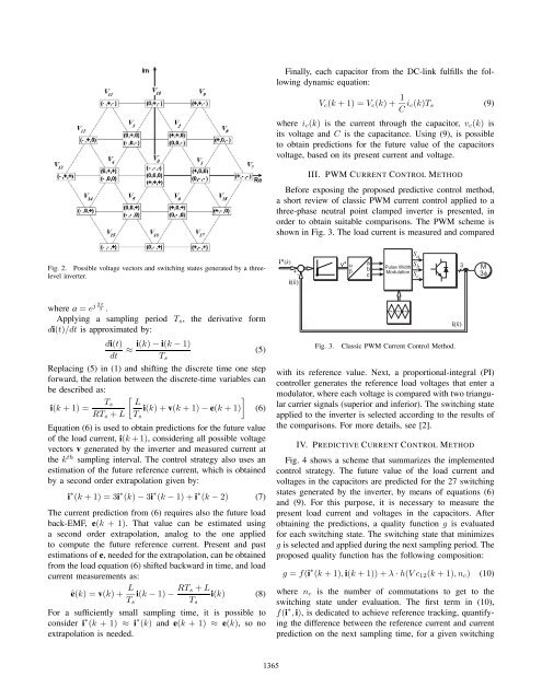
Finally, each capacitor from the DC-link fulfills the followingdynamic equation:V c (k +1)=V c (k)+ 1 C i c(k)T s (9)where i c (k) is the current through the capacitor, v c (k) isits voltage and C is the capacitance. Using (9), is possibleto obtain predictions for the future value <strong>of</strong> the capacitorsvoltage, based on its present current and voltage.III. PWM CURRENT CONTROL METHODBefore exposing the proposed predictive control method,a short review <strong>of</strong> classic PWM current control applied to athree-phase neutral point clamped inverter is presented, inorder to obtain suitable comparisons. The PWM scheme isshown in Fig. 3. The load current is measured and comparedFig. 2. Possible voltage vectors and switching states generated by a threelevelinverter.i*(k)i(k)v*ababcS aSPulse Width bModulationS c+ -Fig. 3. Classic PWM Current <strong>Control</strong> Method.3 M3fwhere a = e j 2π 3 .Applying a sampling period T s , the derivative formdi(t)/dt is approximated by:di(t) i(k) − i(k − 1)≈ (5)dt T sReplacing (5) in (1) and shifting the discrete time one stepforward, the relation between the discrete-time variables canbe described as:[T s Li(k +1)=i(k)+v(k +1)− e(k +1)](6)RT s + L T sEquation (6) is used to obtain predictions for the future value<strong>of</strong> the load current, i(k +1), considering all possible voltagevectors v generated by the inverter and measured current atthe k th sampling interval. The control strategy also uses anestimation <strong>of</strong> the future reference current, which is obtainedby a second order extrapolation given by:i ∗ (k +1)=3i ∗ (k) − 3i ∗ (k − 1) + i ∗ (k − 2) (7)The current prediction from (6) requires also the future loadback-EMF, e(k +1). That value can be estimated usinga second order extrapolation, analog to the one appliedto compute the future reference current. Present and pastestimations <strong>of</strong> e, needed for the extrapolation, can be obtainedfrom the load equation (6) shifted backward in time, and loadcurrent measurements as:ê(k) =v(k)+ L i(k − 1) − RT s + Li(k) (8)T s T sFor a sufficiently small sampling time, it is possible toconsider i ∗ (k +1) ≈ i ∗ (k) and e(k +1) ≈ e(k), sonoextrapolation is needed.with its reference value. Next, a proportional-integral (PI)controller generates the reference load voltages that enter amodulator, where each voltage is compared with two triangularcarrier signals (superior and inferior). The switching stateapplied to the inverter is selected according to the results <strong>of</strong>the comparisons. For more details, see [2].IV. PREDICTIVE CURRENT CONTROL METHODFig. 4 shows a scheme that summarizes the implementedcontrol strategy. The future value <strong>of</strong> the load current andvoltages in the capacitors are predicted for the 27 switchingstates generated by the inverter, by means <strong>of</strong> equations (6)and (9). For this purpose, it is necessary to measure thepresent load current and voltages in the capacitors. Afterobtaining the predictions, a quality function g is evaluatedfor each switching state. The switching state that minimizesg is selected and applied during the next sampling period. Theproposed quality function has the following composition:g = f(i ∗ (k +1), i(k + 1)) + λ · h(Vc 12 (k +1),n c ) (10)where n c is the number <strong>of</strong> commutations to get to theswitching state under evaluation. The first term in (10),f(i ∗ , i), is dedicated to achieve reference tracking, quantifyingthe difference between the reference current and currentprediction on the next sampling time, for a given switchingi(k)1365