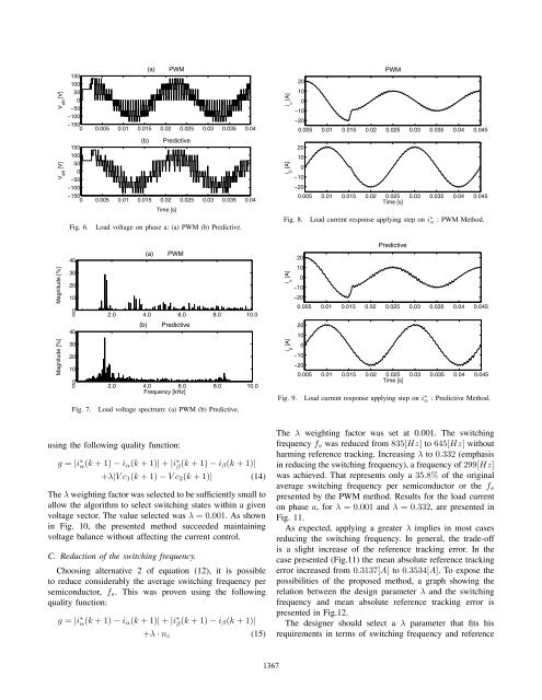
V aN[V]V aN[V](a) PWM150100500−50−100−1500 0.005 0.01 0.015 0.02 0.025 0.03 0.035 0.04(b) <strong>Predictive</strong>150100500−50−100−1500 0.005 0.01 0.015 0.02 0.025 0.03 0.035 0.04Fig. 6.Time [s]Load voltage on phase a: (a) PWM (b) <strong>Predictive</strong>.i β[A]i [A] αPWM20100−10−200.005 0.01 0.015 0.02 0.025 0.03 0.035 0.04 0.04520100−10−200.005 0.01 0.015 0.02 0.025 0.03 0.035 0.04 0.045Time [s]Fig. 8. Load current response applying step on i ∗ α : PWM Method.Magnitude [%]Magnitude [%]40302010(a)PWM02.0 4.0 6.0 8.0 10.040302010(b)<strong>Predictive</strong>02.0 4.0 6.0 8.0 10.0Frequency [kHz]Fig. 7.Load voltage spectrum: (a) PWM (b) <strong>Predictive</strong>.i [A]i [A]β α<strong>Predictive</strong>20100−10−200.005 0.01 0.015 0.02 0.025 0.03 0.035 0.04 0.04520100−10−200.005 0.01 0.015 0.02 0.025 0.03 0.035 0.04 0.045Time [s]Fig. 9. Load current response applying step on i ∗ α : <strong>Predictive</strong> Method.using the following quality function:g = |i ∗ α(k +1)− i α (k +1)| + |i ∗ β (k +1)− i β(k +1)|+λ|Vc 1 (k +1)− Vc 2 (k +1)| (14)The λ weighting factor was selected to be sufficiently small toallow the algorithm to select switching states within a givenvoltage vector. The value selected was λ =0.001. As shownin Fig. 10, the presented method succeeded maintainingvoltage balance without affecting the current control.C. Reduction <strong>of</strong> the switching frequency.Choosing alternative 2 <strong>of</strong> equation (12), it is possibleto reduce considerably the average switching frequency persemiconductor, f s . This was proven using the followingquality function:g = |i ∗ α(k +1)− i α (k +1)| + |i ∗ β (k +1)− i β(k +1)|+λ · n c (15)The λ weighting factor was set at 0.001. The switchingfrequency f s was reduced from 835[Hz] to 645[Hz] withoutharming reference tracking. Increasing λ to 0.332 (emphasisin reducing the switching frequency), a frequency <strong>of</strong> 299[Hz]was achieved. That represents only a 35.8% <strong>of</strong> the originalaverage switching frequency per semiconductor or the f spresented by the PWM method. Results for the load currenton phase a, for λ =0.001 and λ =0.332, are presented inFig. 11.As expected, applying a greater λ implies in most casesreducing the switching frequency. In general, the trade-<strong>of</strong>fis a slight increase <strong>of</strong> the reference tracking error. In thecase presented (Fig.11) the mean absolute reference trackingerror increased from 0.3137[A] to 0.3534[A]. To expose thepossibilities <strong>of</strong> the proposed method, a graph showing therelation between the design parameter λ and the switchingfrequency and mean absolute reference tracking error ispresented in Fig.12.The designer should select a λ parameter that fits hisrequirements in terms <strong>of</strong> switching frequency and reference1367
Vc 1,Vc 2[V]Vc 1,Vc 2[V]20015010050(a) Without applying balance00 0.05 0.1 0.15 0.220015010050(b) Applying balance00 0.05 0.1 0.15 0.2Time [s]SwitchingFrequency [kHz]AbsoluteError [A]0.9λ v/s Switching Frequency0.80.70.60.50.40.30.20 0.05 0.1 0.15 0.2 0.25 0.3 0.350.80.60.40.2λ v/s Absolute Error00 0.05 0.1 0.15 0.2 0.25 0.3 0.35λFig. 10. Voltage in the capacitors <strong>of</strong> the DC-link: (a) Without applyingbalance, quality function (13) (b) Applying balance, quality function (14).Fig. 12. Design parameter λ (a)Relation with the mean switching frequencyper semiconductor (b)Relation with the mean absolute reference trackingerror.i a[A]i a[A](a) High switching frequency20100−10−200.06 0.065 0.07 0.075 0.08 0.085 0.09 0.095 0.120100−10−20(b) Low switching frequency0.06 0.065 0.07 0.075 0.08 0.085 0.09 0.095 0.1Time [s]Fig. 11. Load current on phase a (a)High switching frequency: f s =645[Hz] (b)Emphasis in reducing the switching frequency: f s = 299[Hz].tracking. The lowest mean absolute reference tracking errorachieved was 0.2745[A] or 1.3725% with λ =0.062 andf s = 662[Hz]. The PWM method presented a mean absolutereference tracking error <strong>of</strong> 0.2939[A] or 1.4695% with f s =835[Hz].Summarizing, the reference tracking performance <strong>of</strong> thepredictive method compares well with PWM current control,with lower switching frequency per semiconductor andimproved transitory behavior. Nevertheless, the proposedmethod requires a greater sampling frequency or data acquisitionfrequency. The previous fact should not be a problem,considering the new technologies available in digital signalprocessors.VI. CONCLUSIONThe predictive current control method presented does notrequire any kind <strong>of</strong> linear controller or modulation technique.It presents a very effective control <strong>of</strong> the load current, andcompares well with established control methods, like PWM,achieving a slightly better dynamic response. The proposedmethod presents no interaction between both components <strong>of</strong>the load current.One <strong>of</strong> the remarkable aspects <strong>of</strong> the method is the use <strong>of</strong>state redundancy, in order to achieve balance in the DC-linkand reduction <strong>of</strong> the switching frequency. The strategy allowsthe designer to adjust the λ parameter to fits his requirementsin terms <strong>of</strong> switching frequency and reference tracking.The method can be easily implemented taking advantage <strong>of</strong>the present technologies available in digital signal processors.This control strategy uses, in a very convenient way, thediscrete nature <strong>of</strong> the power converter and the microprocessorused in the control.These results show that predictive control is a very powerfultool, with a conceptually different approach, which opensnew possibilities in the control <strong>of</strong> power converters.ACKNOWLEDGMENTThe authors acknowledge the support <strong>of</strong> the Chilean ResearchFund CONICYT (Grant 1030368) and <strong>of</strong> the UniversidadTécnica Federico Santa María.REFERENCES[1] J. Holtz, Pulsewidth Modulation for Electronic Power Conversion,Proceedings <strong>of</strong> the IEEE, 82(8), 1994.[2] M.P. Kazmierkowski, R. Krishnan and F. Blaabjerg, <strong>Control</strong> in PowerElectronics, Academic Press, 2002.[3] A. Nabae, I. Takahashi, H. Akagi, A New <strong>Neutral</strong>-<strong>Point</strong>-<strong>Clamped</strong> PWM<strong>Inverter</strong>, IEEE Transactions on Industry Applications, vol. IA-17, issue5, Sep./Oct. 1981, pp. 518-523.[4] Y. Tadros, S. Salama, <strong>Three</strong> Level IGBT <strong>Inverter</strong>s for Industrial Drivesand Traction Applications, EPE Journal, vol. 4, no. 2, June 1994, pp.38-42.[5] M. K. Buschmann, J. K. Steinke, Robust and Reliable Medium VoltagePWM <strong>Inverter</strong> with Motor Friendly Output, 7 th European Conferenceon Power Electronics and Applications, Trondheim (1997), pp. 3.502-3.507.1368