Predictive Control of a Three-Phase Neutral Point Clamped Inverter
Predictive Control of a Three-Phase Neutral Point Clamped Inverter
Predictive Control of a Three-Phase Neutral Point Clamped Inverter
- No tags were found...
You also want an ePaper? Increase the reach of your titles
YUMPU automatically turns print PDFs into web optimized ePapers that Google loves.
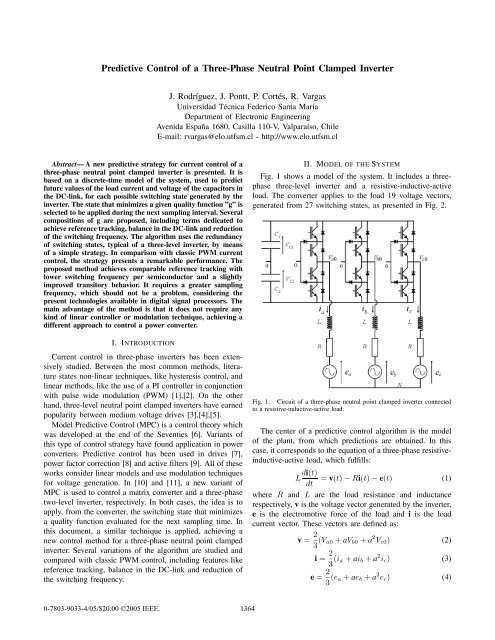
<strong>Predictive</strong> <strong>Control</strong> <strong>of</strong> a <strong>Three</strong>-<strong>Phase</strong> <strong>Neutral</strong> <strong>Point</strong> <strong>Clamped</strong> <strong>Inverter</strong>J. Rodríguez, J. Pontt, P. Cortés, R. VargasUniversidad Técnica Federico Santa MaríaDepartment <strong>of</strong> Electronic EngineeringAvenida España 1680, Casilla 110-V, Valparaíso, ChileE-mail: rvargas@elo.utfsm.cl - http://www.elo.utfsm.clAbstract— A new predictive strategy for current control <strong>of</strong> athree-phase neutral point clamped inverter is presented. It isbased on a discrete-time model <strong>of</strong> the system, used to predictfuture values <strong>of</strong> the load current and voltage <strong>of</strong> the capacitors inthe DC-link, for each possible switching state generated by theinverter. The state that minimizes a given quality function ”g” isselected to be applied during the next sampling interval. Severalcompositions <strong>of</strong> g are proposed, including terms dedicated toachieve reference tracking, balance in the DC-link and reduction<strong>of</strong> the switching frequency. The algorithm uses the redundancy<strong>of</strong> switching states, typical <strong>of</strong> a three-level inverter, by means<strong>of</strong> a simple strategy. In comparison with classic PWM currentcontrol, the strategy presents a remarkable performance. Theproposed method achieves comparable reference tracking withlower switching frequency per semiconductor and a slightlyimproved transitory behavior. It requires a greater samplingfrequency, which should not be a problem, considering thepresent technologies available in digital signal processors. Themain advantage <strong>of</strong> the method is that it does not require anykind <strong>of</strong> linear controller or modulation technique, achieving adifferent approach to control a power converter.I. INTRODUCTIONCurrent control in three-phase inverters has been extensivelystudied. Between the most common methods, literaturestates non-linear techniques, like hysteresis control, andlinear methods, like the use <strong>of</strong> a PI controller in conjunctionwith pulse wide modulation (PWM) [1],[2]. On the otherhand, three-level neutral point clamped inverters have earnedpopularity between medium voltage drives [3],[4],[5].Model <strong>Predictive</strong> <strong>Control</strong> (MPC) is a control theory whichwas developed at the end <strong>of</strong> the Seventies [6]. Variants <strong>of</strong>this type <strong>of</strong> control strategy have found application in powerconverters. <strong>Predictive</strong> control has been used in drives [7],power factor correction [8] and active filters [9]. All <strong>of</strong> theseworks consider linear models and use modulation techniquesfor voltage generation. In [10] and [11], a new variant <strong>of</strong>MPC is used to control a matrix converter and a three-phasetwo-level inverter, respectively. In both cases, the idea is toapply, from the converter, the switching state that minimizesa quality function evaluated for the next sampling time. Inthis document, a similar technique is applied, achieving anew control method for a three-phase neutral point clampedinverter. Several variations <strong>of</strong> the algorithm are studied andcompared with classic PWM control, including features likereference tracking, balance in the DC-link and reduction <strong>of</strong>the switching frequency.II. MODEL OF THE SYSTEMFig. 1 shows a model <strong>of</strong> the system. It includes a threephasethree-level inverter and a resistive-inductive-activeload. The converter applies to the load 19 voltage vectors,generated from 27 switching states, as presented in Fig. 2.Fig. 1. Circuit <strong>of</strong> a three-phase neutral point clamped inverter connectedto a resistive-inductive-active load.The center <strong>of</strong> a predictive control algorithm is the model<strong>of</strong> the plant, from which predictions are obtained. In thiscase, it corresponds to the equation <strong>of</strong> a three-phase resistiveinductive-activeload, which fulfills:L di(t) = v(t) − Ri(t) − e(t) (1)dtwhere R and L are the load resistance and inductancerespectively, v is the voltage vector generated by the inverter,e is the electromotive force <strong>of</strong> the load and i is the loadcurrent vector. These vectors are defined as:v = 2 3 (V a0 + aV b0 + a 2 V c0 ) (2)i = 2 3 (i a + ai b + a 2 i c ) (3)e = 2 3 (e a + ae b + a 2 e c ) (4)0-7803-9033-4/05/$20.00 ©2005 IEEE.1364
Finally, each capacitor from the DC-link fulfills the followingdynamic equation:V c (k +1)=V c (k)+ 1 C i c(k)T s (9)where i c (k) is the current through the capacitor, v c (k) isits voltage and C is the capacitance. Using (9), is possibleto obtain predictions for the future value <strong>of</strong> the capacitorsvoltage, based on its present current and voltage.III. PWM CURRENT CONTROL METHODBefore exposing the proposed predictive control method,a short review <strong>of</strong> classic PWM current control applied to athree-phase neutral point clamped inverter is presented, inorder to obtain suitable comparisons. The PWM scheme isshown in Fig. 3. The load current is measured and comparedFig. 2. Possible voltage vectors and switching states generated by a threelevelinverter.i*(k)i(k)v*ababcS aSPulse Width bModulationS c+ -Fig. 3. Classic PWM Current <strong>Control</strong> Method.3 M3fwhere a = e j 2π 3 .Applying a sampling period T s , the derivative formdi(t)/dt is approximated by:di(t) i(k) − i(k − 1)≈ (5)dt T sReplacing (5) in (1) and shifting the discrete time one stepforward, the relation between the discrete-time variables canbe described as:[T s Li(k +1)=i(k)+v(k +1)− e(k +1)](6)RT s + L T sEquation (6) is used to obtain predictions for the future value<strong>of</strong> the load current, i(k +1), considering all possible voltagevectors v generated by the inverter and measured current atthe k th sampling interval. The control strategy also uses anestimation <strong>of</strong> the future reference current, which is obtainedby a second order extrapolation given by:i ∗ (k +1)=3i ∗ (k) − 3i ∗ (k − 1) + i ∗ (k − 2) (7)The current prediction from (6) requires also the future loadback-EMF, e(k +1). That value can be estimated usinga second order extrapolation, analog to the one appliedto compute the future reference current. Present and pastestimations <strong>of</strong> e, needed for the extrapolation, can be obtainedfrom the load equation (6) shifted backward in time, and loadcurrent measurements as:ê(k) =v(k)+ L i(k − 1) − RT s + Li(k) (8)T s T sFor a sufficiently small sampling time, it is possible toconsider i ∗ (k +1) ≈ i ∗ (k) and e(k +1) ≈ e(k), sonoextrapolation is needed.with its reference value. Next, a proportional-integral (PI)controller generates the reference load voltages that enter amodulator, where each voltage is compared with two triangularcarrier signals (superior and inferior). The switching stateapplied to the inverter is selected according to the results <strong>of</strong>the comparisons. For more details, see [2].IV. PREDICTIVE CURRENT CONTROL METHODFig. 4 shows a scheme that summarizes the implementedcontrol strategy. The future value <strong>of</strong> the load current andvoltages in the capacitors are predicted for the 27 switchingstates generated by the inverter, by means <strong>of</strong> equations (6)and (9). For this purpose, it is necessary to measure thepresent load current and voltages in the capacitors. Afterobtaining the predictions, a quality function g is evaluatedfor each switching state. The switching state that minimizesg is selected and applied during the next sampling period. Theproposed quality function has the following composition:g = f(i ∗ (k +1), i(k + 1)) + λ · h(Vc 12 (k +1),n c ) (10)where n c is the number <strong>of</strong> commutations to get to theswitching state under evaluation. The first term in (10),f(i ∗ , i), is dedicated to achieve reference tracking, quantifyingthe difference between the reference current and currentprediction on the next sampling time, for a given switchingi(k)1365
i*(k+1)(i(k+1),Vc 1,2 (k+1)) i27S aMinimization S<strong>of</strong> bg function S c<strong>Predictive</strong>modeli(k)Vc 1,2 (k)3 M3fTABLE ICIRCUIT PARAMETERS.C 1 , C 2 1[mF]R 0.5[Ω]L 10[mH]EMF Amplitude 50[V]EMF Frequency 50[Hz]Fig. 4.<strong>Predictive</strong> Current <strong>Control</strong> Method.(a)PWMstate. The following composition <strong>of</strong> f, or”tracking cost”, isproposed:f(i ∗ (k +1), i(k + 1)) = |i ∗ α(k +1)− i α (k +1)|+ |i ∗ β (k +1)− i β(k +1)| (11)where i α and i β are the real and imaginary components <strong>of</strong>current vector i, respectively, and i ∗ α and i ∗ βare the real andimaginary components <strong>of</strong> the reference current vector i ∗ .The objective <strong>of</strong> the second term in (10), λ · h(Vc 12 ,n c ),is to take advantage <strong>of</strong> the state redundancy <strong>of</strong> a three-levelinverter from the fact that the tracking cost f depends onlyon the voltage vector selected. Two possible compositions <strong>of</strong>h are proposed:{ = |Vc1 (k +1)− Vch(Vc 12 (k +1),n c )2 (k +1)|(12)= n cThe first choice, adds up to g a term proportional to theabsolute difference between both capacitors voltage predictions.A switching state that generates smaller differenceswill be preferred. The second option is simply the number <strong>of</strong>commutations to get to the next switching state. A switchingstate that implies fewer commutations will be preferred. Theλ weighting factor multiplying h in (10), handles the relationbetween f and h in g. A small λ implies greater priority toreference tracking over balance in the DC-link or reduction<strong>of</strong> the switching frequency.V. RESULTSResults for the proposed predictive current control strategyare presented. Within this section, the DC-link will be maintainedin 200[V ], following a previous rectification stage. Thesampling period applied is T s = 100[µs]. Values <strong>of</strong> the DC-Link and load parameters (Fig. 1) are shown in Table I.A. Reference Tracking.Performance <strong>of</strong> the proposed strategy is analyzed andcompared with PWM current control. The algorithm wasimplemented using the following quality function:g = |i ∗ α(k +1)− i α (k +1)| + |i ∗ β(k +1)− i β (k +1)| (13)In order to generate the same average switching frequency persemiconductor as the predictive method, <strong>of</strong> about 835[Hz],the PWM carrier frequency was set to 1670[Hz].i α,β[A]i α,β[A]20100−10−2020100−10−200 0.005 0.01 0.015 0.02 0.025 0.03 0.035 0.04(b)<strong>Predictive</strong>0 0.005 0.01 0.015 0.02 0.025 0.03 0.035 0.04Time [s]Fig. 5.Load current response : (a) PWM (b) <strong>Predictive</strong>.Waveforms obtained for the load current, load voltage andvoltage spectrum for both methods are presented in Figs. 5,6 and 7. Figs. 5 and 6 show the initial transient response,starting from zero load current until reaching stationarystate. The load voltage spectrum obtained with the <strong>Predictive</strong>method is more spread than with the PWM method, as shownin Fig. 7. This could be considered a disadvantage <strong>of</strong> themethod.In order to observe the interaction between both components<strong>of</strong> the load current, the amplitude <strong>of</strong> i ∗ α (real component<strong>of</strong> the reference current) is reduced from 20[A] to 10[A] attime t =0.015[s]. The imaginary component is left at 20[A].Results for the load current are presented in Figs. 8 and 9, forPWM and <strong>Predictive</strong> methods. From the presented results,it is clear that the predictive method achieves comparableperformance on reference tracking during transient response,without needing modulation techniques or to adjust any kind<strong>of</strong> linear controllers. In addition, note that the proposedmethod presents no interaction between i α and i β . Thedecoupling <strong>of</strong> both components <strong>of</strong> the current vector is aninherent property <strong>of</strong> the predictive method.B. Balance in the DC-link.Balance is achieved including the term presented in alternative1 <strong>of</strong> equation (12). The method was implemented1366
V aN[V]V aN[V](a) PWM150100500−50−100−1500 0.005 0.01 0.015 0.02 0.025 0.03 0.035 0.04(b) <strong>Predictive</strong>150100500−50−100−1500 0.005 0.01 0.015 0.02 0.025 0.03 0.035 0.04Fig. 6.Time [s]Load voltage on phase a: (a) PWM (b) <strong>Predictive</strong>.i β[A]i [A] αPWM20100−10−200.005 0.01 0.015 0.02 0.025 0.03 0.035 0.04 0.04520100−10−200.005 0.01 0.015 0.02 0.025 0.03 0.035 0.04 0.045Time [s]Fig. 8. Load current response applying step on i ∗ α : PWM Method.Magnitude [%]Magnitude [%]40302010(a)PWM02.0 4.0 6.0 8.0 10.040302010(b)<strong>Predictive</strong>02.0 4.0 6.0 8.0 10.0Frequency [kHz]Fig. 7.Load voltage spectrum: (a) PWM (b) <strong>Predictive</strong>.i [A]i [A]β α<strong>Predictive</strong>20100−10−200.005 0.01 0.015 0.02 0.025 0.03 0.035 0.04 0.04520100−10−200.005 0.01 0.015 0.02 0.025 0.03 0.035 0.04 0.045Time [s]Fig. 9. Load current response applying step on i ∗ α : <strong>Predictive</strong> Method.using the following quality function:g = |i ∗ α(k +1)− i α (k +1)| + |i ∗ β (k +1)− i β(k +1)|+λ|Vc 1 (k +1)− Vc 2 (k +1)| (14)The λ weighting factor was selected to be sufficiently small toallow the algorithm to select switching states within a givenvoltage vector. The value selected was λ =0.001. As shownin Fig. 10, the presented method succeeded maintainingvoltage balance without affecting the current control.C. Reduction <strong>of</strong> the switching frequency.Choosing alternative 2 <strong>of</strong> equation (12), it is possibleto reduce considerably the average switching frequency persemiconductor, f s . This was proven using the followingquality function:g = |i ∗ α(k +1)− i α (k +1)| + |i ∗ β (k +1)− i β(k +1)|+λ · n c (15)The λ weighting factor was set at 0.001. The switchingfrequency f s was reduced from 835[Hz] to 645[Hz] withoutharming reference tracking. Increasing λ to 0.332 (emphasisin reducing the switching frequency), a frequency <strong>of</strong> 299[Hz]was achieved. That represents only a 35.8% <strong>of</strong> the originalaverage switching frequency per semiconductor or the f spresented by the PWM method. Results for the load currenton phase a, for λ =0.001 and λ =0.332, are presented inFig. 11.As expected, applying a greater λ implies in most casesreducing the switching frequency. In general, the trade-<strong>of</strong>fis a slight increase <strong>of</strong> the reference tracking error. In thecase presented (Fig.11) the mean absolute reference trackingerror increased from 0.3137[A] to 0.3534[A]. To expose thepossibilities <strong>of</strong> the proposed method, a graph showing therelation between the design parameter λ and the switchingfrequency and mean absolute reference tracking error ispresented in Fig.12.The designer should select a λ parameter that fits hisrequirements in terms <strong>of</strong> switching frequency and reference1367
Vc 1,Vc 2[V]Vc 1,Vc 2[V]20015010050(a) Without applying balance00 0.05 0.1 0.15 0.220015010050(b) Applying balance00 0.05 0.1 0.15 0.2Time [s]SwitchingFrequency [kHz]AbsoluteError [A]0.9λ v/s Switching Frequency0.80.70.60.50.40.30.20 0.05 0.1 0.15 0.2 0.25 0.3 0.350.80.60.40.2λ v/s Absolute Error00 0.05 0.1 0.15 0.2 0.25 0.3 0.35λFig. 10. Voltage in the capacitors <strong>of</strong> the DC-link: (a) Without applyingbalance, quality function (13) (b) Applying balance, quality function (14).Fig. 12. Design parameter λ (a)Relation with the mean switching frequencyper semiconductor (b)Relation with the mean absolute reference trackingerror.i a[A]i a[A](a) High switching frequency20100−10−200.06 0.065 0.07 0.075 0.08 0.085 0.09 0.095 0.120100−10−20(b) Low switching frequency0.06 0.065 0.07 0.075 0.08 0.085 0.09 0.095 0.1Time [s]Fig. 11. Load current on phase a (a)High switching frequency: f s =645[Hz] (b)Emphasis in reducing the switching frequency: f s = 299[Hz].tracking. The lowest mean absolute reference tracking errorachieved was 0.2745[A] or 1.3725% with λ =0.062 andf s = 662[Hz]. The PWM method presented a mean absolutereference tracking error <strong>of</strong> 0.2939[A] or 1.4695% with f s =835[Hz].Summarizing, the reference tracking performance <strong>of</strong> thepredictive method compares well with PWM current control,with lower switching frequency per semiconductor andimproved transitory behavior. Nevertheless, the proposedmethod requires a greater sampling frequency or data acquisitionfrequency. The previous fact should not be a problem,considering the new technologies available in digital signalprocessors.VI. CONCLUSIONThe predictive current control method presented does notrequire any kind <strong>of</strong> linear controller or modulation technique.It presents a very effective control <strong>of</strong> the load current, andcompares well with established control methods, like PWM,achieving a slightly better dynamic response. The proposedmethod presents no interaction between both components <strong>of</strong>the load current.One <strong>of</strong> the remarkable aspects <strong>of</strong> the method is the use <strong>of</strong>state redundancy, in order to achieve balance in the DC-linkand reduction <strong>of</strong> the switching frequency. The strategy allowsthe designer to adjust the λ parameter to fits his requirementsin terms <strong>of</strong> switching frequency and reference tracking.The method can be easily implemented taking advantage <strong>of</strong>the present technologies available in digital signal processors.This control strategy uses, in a very convenient way, thediscrete nature <strong>of</strong> the power converter and the microprocessorused in the control.These results show that predictive control is a very powerfultool, with a conceptually different approach, which opensnew possibilities in the control <strong>of</strong> power converters.ACKNOWLEDGMENTThe authors acknowledge the support <strong>of</strong> the Chilean ResearchFund CONICYT (Grant 1030368) and <strong>of</strong> the UniversidadTécnica Federico Santa María.REFERENCES[1] J. Holtz, Pulsewidth Modulation for Electronic Power Conversion,Proceedings <strong>of</strong> the IEEE, 82(8), 1994.[2] M.P. Kazmierkowski, R. Krishnan and F. Blaabjerg, <strong>Control</strong> in PowerElectronics, Academic Press, 2002.[3] A. Nabae, I. Takahashi, H. Akagi, A New <strong>Neutral</strong>-<strong>Point</strong>-<strong>Clamped</strong> PWM<strong>Inverter</strong>, IEEE Transactions on Industry Applications, vol. IA-17, issue5, Sep./Oct. 1981, pp. 518-523.[4] Y. Tadros, S. Salama, <strong>Three</strong> Level IGBT <strong>Inverter</strong>s for Industrial Drivesand Traction Applications, EPE Journal, vol. 4, no. 2, June 1994, pp.38-42.[5] M. K. Buschmann, J. K. Steinke, Robust and Reliable Medium VoltagePWM <strong>Inverter</strong> with Motor Friendly Output, 7 th European Conferenceon Power Electronics and Applications, Trondheim (1997), pp. 3.502-3.507.1368
[6] E. Camacho, C. Bordones, Model <strong>Predictive</strong> <strong>Control</strong>, Springer, 1999.[7] R. Kennel, A. Linder, <strong>Predictive</strong> <strong>Control</strong> <strong>of</strong> <strong>Inverter</strong> Supplied ElectricalDrives, Conf. Record <strong>of</strong> PESC’00 (Power Electronics SpecialistsConference), Ireland, 2000. CD-ROM.[8] P. Mattavelli, G. Spiazzi, P. Tenti, <strong>Predictive</strong> Digital <strong>Control</strong> <strong>of</strong> PowerFactor Preregulators, Conf. Record <strong>of</strong> PESC’03 (Power ElectronicsSpecialists Conference), Mexico, 2003. CD-ROM.[9] P. Malesani, P. Mattavelli, S. Buso, Robust Dead-beat Current <strong>Control</strong>for PWM Rectifier and Active Filters, IEEE Transactions on IndustryApplications, vol. 35, issue 3, May/June 1999, pp. 613-620.[10] S. Müller, U. Ammann, S. Rees, New Modulation Strategy for a MatrixConverter with a Very Small Mains Filter, Conf. Record <strong>of</strong> PESC’03(Power Electronics Specialists Conference), Mexico, 2003. CD-ROM.[11] J. Rodríguez, J. Pontt, C. Silva, M. Salgado, S. Rees, U. Ammann,P. Lezana, R. Huerta, P. Cortés, <strong>Predictive</strong> <strong>Control</strong> <strong>of</strong> a <strong>Three</strong>-phase<strong>Inverter</strong>, IEE Electronics Letters , Volume: 40 , Issue: 9, 29 April 2004,pp. 561-562.1369


