

Sporlan TXV Inst Se.. - HVAC.Amickracing
Sporlan TXV Inst Se.. - HVAC.Amickracing
Sporlan TXV Inst Se.. - HVAC.Amickracing

You also want an ePaper? Increase the reach of your titles
YUMPU automatically turns print PDFs into web optimized ePapers that Google loves.
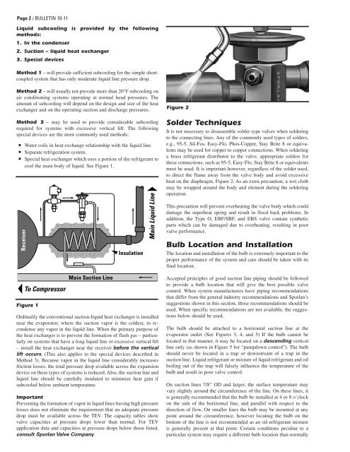
Page 2 / BULLETIN 10-11Liquid subcooling is provided by the followingmethods:1. In the condenser2. Suction – liquid heat exchanger3. Special devicesMethod 1 – will provide sufficient subcooling for the simple shortcoupledsystem that has only moderate liquid line pressure drop.Method 2 – will usually not provide more than 20°F subcooling onair conditioning systems operating at normal head pressures. Theamount of subcooling will depend on the design and size of the heatexchanger and on the operating suction and discharge pressures.Method 3 – may be used to provide considerable subcoolingrequired for systems with excessive vertical lift. The followingspecial devices are the most commonly used methods:■■■Water coils in heat exchange relationship with the liquid line.<strong>Se</strong>parate refrigeration system.Special heat exchanger which uses a portion of the refrigerant tocool the main body of liquid. <strong>Se</strong>e Figure 1.ReceiverTo CompressorFigure 1Main Suction LineInsulationMain Liquid LineOrdinarily the conventional suction-liquid heat exchanger is installednear the evaporator, where the suction vapor is the coldest, to recondenseany vapor in the liquid line. When the primary purpose ofthe heat exchanger is to prevent the formation of flash gas – particularlyon systems that have a long liquid line or excessive vertical lift– install the heat exchanger near the receiver before the verticallift occurs. (This also applies to the special devices described inMethod 3). Because vapor in the liquid line considerably increasesfriction losses, the total pressure drop available across the expansiondevice on these types of systems is reduced. Also, the suction line andliquid line should be carefully insulated to minimize heat gain ifsubcooled below ambient temperature.ImportantPreventing the formation of vapor in liquid lines having high pressurelosses does not eliminate the requirement that an adequate pressuredrop must be available across the TEV. The capacity tables showvalve capacities at pressure drops lower than normal. For TEVapplication data and capacities at pressure drops below those listed,consult <strong>Sporlan</strong> Valve Company.Figure 2Solder TechniquesIt is not necessary to disassemble solder type valves when solderingto the connecting lines. Any of the commonly used types of solders,e.g., 95-5, Sil-Fos, Easy-Flo, Phos-Copper, Stay Brite 8 or equivalentsmay be used for copper to copper connections. When solderinga brass refrigerant distributor to the valve, appropriate solders forthese connections, such as 95-5, Easy-Flo, Stay Brite 8 or equivalentsmust be used. It is important however, regardless of the solder used,to direct the flame away from the valve body and avoid excessiveheat on the diaphragm, Figure 2. As an extra precaution, a wet clothmay be wrapped around the body and element during the solderingoperation.This precaution will prevent overheating the valve body which coulddamage the superheat spring and result in flood back problems. Inaddition, the Type O, EBF/SBF, and EBS valve contain syntheticparts which can be damaged due to overheating, resulting in poorvalve performance.Bulb Location and <strong>Inst</strong>allationThe location and installation of the bulb is extremely important to theproper performance of the system and care should be taken with itsfinal location.Accepted principles of good suction line piping should be followedto provide a bulb location that will give the best possible valvecontrol. When system manufacturers have piping recommendationsthat differ from the general industry recommendations and <strong>Sporlan</strong>’ssuggestions shown in this section, those recommendations should beused. When specific recommendations are not available, the suggestionsbelow should be used.The bulb should be attached to a horizontal suction line at theevaporator outlet (<strong>Se</strong>e Figures 3, 4, and 5) If the bulb cannot belocated in that manner, it may be located on a descending verticalline only (as shown in Figure 5 for “pumpdown control”). The bulbshould never be located in a trap or downstream of a trap in thesuction line. Liquid refrigerant or mixture of liquid refrigerant and oilboiling out of the trap will falsely influence the temperature of thebulb and result in poor valve control.On suction lines 7/8” OD and larger, the surface temperature mayvary slightly around the circumference of the line. On these lines, itis generally recommended that the bulb be installed at 4 or 8 o’clockon the side of the horizontal line, and parallel with respect to thedirection of flow. On smaller lines the bulb may be mounted at anypoint around the circumference, however locating the bulb on thebottom of the line is not recommended as an oil-refrigerant mixtureis generally present at that point. Certain conditions peculiar to aparticular system may require a different bulb location than normally


