APEX DYNAMICS, INC.
APEX DYNAMICS, INC.
APEX DYNAMICS, INC.

Create successful ePaper yourself
Turn your PDF publications into a flip-book with our unique Google optimized e-Paper software.
<strong>APEX</strong> <strong>DYNAMICS</strong>, <strong>INC</strong>.
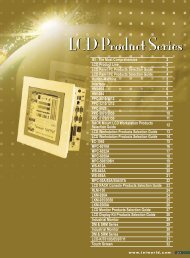
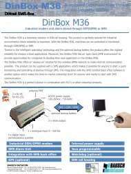
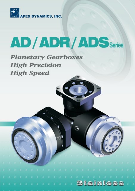
AD / ADR / ADS SeriesCharacteristic HighlightsPlanet gears rotate on solid uncaged needle roller bearings forincreased stiffness and the maximum number of contact points.Hardened thrust washers allow the precise control of clearancesin order to eliminate backlash.Helical gear design. Helicalgearing increases the tooth to toothcontact ratio by as much as 33%,Benefits include increased torquecapacity , ultimate smoothness,lower backlash and decreasednoise. The helix angle is carefullychosen to gain these advantageswhile not producing excessive axialforces.Lubrication by synthetic Nyogel 792Dgrease for smooth operation over thewhole service life, Sealed to IP65standard for ingress protection and canbe mounted in any orientation .Patented planet carrier designmounts the sun gear bearing directlyinto the planet carrier in order toeliminate misalignment. This exclusivedesign offers great advantages indecreased noise, vibration andtransmission errors and losses.Triple-split collet and dynamically balanced setcollar clamping system for efficient powertransmission. Perfect concentricity from one-piecesun gear reduces backlash and allows higher inputspeeds.ADR SeriesIndustry-leading gear performance is attained with our HeliTopotechnology. Ease off of the tooth profile and lead crowningoptimizes the gear mesh under load and achieves maximum toothsurface contact.ADR versionowith 90 input viaspiral bevel gear. Featuring anextremely short, rigid housingwith full compatibility to anymotor.Our In-house plasma nitriding treatment process allows thehardness of the gear flanks to reach over 900Hv for superior wearresistance and still maintain a core hardness of 30HRc fortoughness and resistance to shock loading.One-piece carrier and output housing ensure 100% concentricityand alignment of all the rotating components. One-piececonstruction increases strength, rigidity and system reliability.Patented sealing system featuring aTiCN coated shaft surface thateliminates leakage and increasesservice life to over 30,000 hours. Thehigh tech coating, with a surface qualityof 0.2μm and hardness of 3700 Hv.Interfaces with our proprietary seal,decreasing wear and runningtemperature.ADS version speciallydesigned input shaft with keyand threaded hole. Easy todrive via timing belt pulley orcoupling. For increasing designflexibility and space saving formotor mounting. Ideal forhighly dynamic cyclic duty orcontinuous running application.ADS Series<strong>APEX</strong> 1<strong>APEX</strong> 2
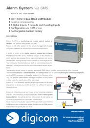
AD SeriesSpecificationsGearbox PerformanceModel No.Nominal Output Torque T 2NEmergency Stop Torque T 2NOT2Nominal Input Speed n 1NMax. Input Speed n 1BMicro Backlash P0Reduced Backlash P1Standard Backlash P2Torsional RigidityMax. Bending moment M 2KB3Max. Axial Load F 2B3Service LifeWeightOperating TempLubricationDegree of Gearbox ProtectionMounting PositionNoise Level (n1=3000rpm)Gearbox InertiaNmNmrpmrpmarcminarcminarcminNm/arcminNmNhr%kgoCdBStage Ratio 1 AD047 AD064 AD090 AD110 AD140 AD200 AD2554 19 48 130 270 560 1,100 1,7005 22 60 160 330 650 1,200 2,0001 7 19 50 140 300 550 1,100 1,80010 14 40 100 230 450 900 1,50020 19 48 130 270 560 1,100 1,70025 22 60 160 330 650 1,200 2,00035 19 50 140 300 550 1,100 1,80040 19 48 130 270 560 1,100 1,70050 22 60 160 330 650 1,200 2,00070 19 50 140 300 550 1,100 1,8002 100 14 40 100 230 450 900 1,50016 19 48 130 270 560 1,100 1,70021 22 60 160 330 650 1,200 2,00031 19 50 140 300 550 1,100 1,80061 19 50 140 300 550 1,100 1,80091 14 40 100 230 450 900 1,5004~1003 times of Nominal Output Torque4~1004~1005,00010,0005,00010,0004,0008,0004,0008,0003,0006,0003,0006,0002,0004,0004~10 - - ≤1 ≤1 ≤1 ≤1 ≤120~100 - - - ≤3 ≤3 ≤3 ≤34~10 ≤3 ≤3 ≤3 ≤3 ≤3 ≤3 ≤320~100 ≤5 ≤5 ≤5 ≤5 ≤5 ≤5 ≤54~10 ≤5 ≤5 ≤5 ≤5 ≤5 ≤5 ≤51,21,21,21212121,21,21,21,212121,21,21,21,21,220~100 ≤7 ≤7 ≤7 ≤7 ≤7 ≤7 ≤74~100 7 13 31 82 151 440 1,0064~1004~10042.51,0801252,1102352,3104304,8001,3006,2003,0645,4505,90010,6004~10030,000*4~10≥97%20~100≥94%4~1020~10016~914~1004~1004~1004~1004~1000.71.01.0Model No. Stage Ratio 1AD047 AD064 AD090 AD110 AD140 AD200 AD2554 0.03 0.14 0.51 2.87 7.54 25.03 58.3115 0.03 0.13 0.47 2.71 7.42 23.29 53.277 0.03 0.13 0.45 2.62 7.14 22.48 50.9710200.030.030.130.030.440.132.570.477.032.7122.517.4250.5623.2925 0.03 0.03 0.13 0.47 2.71 7.42 23.2935 0.03 0.03 0.13 0.47 2.71 7.42 23.29Mass Moments of Inertia J 1240 0.03 0.03 0.13 0.44 2.57 7.03 22.51kg‧cm50 0.03 0.03 0.13 0.44 2.57 7.03 22.51270 0.03 0.03 0.13 0.44 2.57 7.03 22.51100 0.03 0.03 0.13 0.44 2.57 7.03 22.5116213161910.030.030.030.030.030.030.030.030.030.030.130.130.130.130.130.470.470.440.440.442.712.712.572.572.577.427.427.037.037.0323.2923.2922.5122.5122.511. Ratio ( i=N in / N out )2. T 2B = 60% of T2NOT3. Applied to the output shaft center @ 100 rpm*S1 service life 15,000 hrs<strong>APEX</strong> 31.21.61.43.03.73.55.67.36.5o-10 C~+90 oC11.915.915.531.636.934.2synthetic gear grease (NYOGEL 792D)56.170.467.2IP65all directions≤56 ≤58 ≤60 ≤63 ≤65 ≤67 ≤70
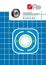
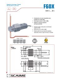
Dimensions (1-stage, Ratio i=4~10)C9L4L6L8C8L3L5L7C10L10x45°C7ØD7ØD5ØD4h7ØD12ØD3h7ØD2D6 ØD1H7ØD8H7L9 Dep.L1ØC3ØC5G6ØD9ØD11h745°45°Flange Dimensionsaccording to ISO 9409AD064-AD255ØD10L2ODO-RingC6C4C2ØC1DimensionD1 H7D2D3 h7D4 h7D5D6D7D8 H7D9D10D11 h7D12L1L2L3L4L5L6L7L8L9L10C1 4C2 4C3 4C4 4C54 G6C6 4C7 4C8 4C9 4C10 4OD<strong>APEX</strong> 4[unit: mm]AD047 AD064 AD090 AD110 AD140 AD200 AD25512202847674 x M3 x 0.5P72345.58 x 3.46046.246.5319.574518.540.546M4 x 0.7P≤1130303.54819.57013.2556 x 22031.54064797 x M5 x 0.8P865558 x 4.57063.288319.5747.728.560.570M5 x 0.8P*≤14 / ≤1634508601982.513.566 x 231.5 40 50 80 10050 63 80 125 14063 80 100 160 18090 110 140 200 255109 135 168 233 2807 x M6 x 1P 11 x M6 x1P 11 x M8 x 1.25P 11 x M10 x 1.5P 12 x M16 x 2P118 145 179 247 3006 6 8 10 1277 90 113 138 1758 x 5.5 8 x 5.5 12 x 6.6 12 x 9 16 x 13.59589.2120109.2152139.2212199.2255254.212 12 12 16 2013.5 13.5 17 22.5 30.56 6 6 8 1230 29 38 50 6610 10 14.6 15 207 8 10 12 188 10 12 15 2027 37 62 69.5 827 7 7 10 101 1 1 1 1100 130 165 215 235M6 x 1P M8 x 1.25P M10 x 1.5P M12 x 1.75P M12 x 1.75P≤19 / ≤24 ≤32 ≤38 ≤48 ≤5540 50 60 85 11680 110 130 180 2004 5 6 6 690 115 142 190 22017 19.5 22.5 29 6399.5 121.5 151 199.5 256.510.75 13 15 20.75 53.590 x 3 110 x 3 145 x 3 200 x 5 238 x 54. C1~C10 are motor specific dimensions (metric std shown). Refer to apexdyna.com and design tool to view your specific motor mounting system.*AD064 ratio 5, 10 offers C3 ≤ 16 option .
AD SeriesDimensions (2-stage, Ratio i=20~100)C9L4L6L8C8L3L5L7C10L10x45°C745°ØD7ØD5ØD4h7ØD12ØD3h7ØD2ØD1H7ØD8H7L9 Dep.L1ØC3ØD9ØC5 G6ØD11h745°D6Flange Dimensionsaccording to ISO 9409AD064-AD255ØD10L2ODO-RingC4C6C2ØC1DimensionD1 H7D2D3 h7D4 h7D5D6D7D8 H7D9D10D11 h7D12L1L2L3L4L5L6L7L8L9L10C1 5C2 5C3 5C4 5C55 G6C6 5C7 5C8 5C9 5C10 5OD<strong>APEX</strong> 5[unit: mm]AD047 AD064 AD090AD110 AD140 AD200 AD25512202847674 x M3 x 0.5P72345.58 x 3.46046.246.5319.574554.540.546M4 x 0.7P≤1130303.54819.597.513.2556 x 22031.54064797 x M5 x 0.8P86545.58 x 4.57063.288319.5747.76560.546M4 x 0.7P*≤11 / ≤1230303.54819.510813.2566 x 231.5 40 50 80 10050 63 80 125 14063 80 100 160 18090 110 140 200 255109 135 168 233 2807 x M6 x 1P 11 x M6 x1P 11 x M8 x 1.25P 11 x M10 x 1.5P 12 x M16 x 2P118 145 179 247 3006 6 8 10 1253.4 77 102 125 1608 x 5.5 8 x 5.5 12 x 6.6 12 x 9 16 x 13.59589.2120109.2152139.2212199.2255254.212 12 12 16 2013.5 13.5 17 22.5 30.56 6 6 8 1230 29 38 50 6610 10 14.6 15 207 8 10 12 188 10 12 15 2060 87.5 110 132.5 1487 7 7 10 101 1 1 1 170 100 130 165 215M5 x 0.8P M6 x 1P M8 x 1.25P M10 x 1.5P M12 x 1.75P*≤14 / ≤15.875 / ≤16 ≤19 / ≤24 ≤32 ≤38 ≤4834 40 50 60 8550 80 110 130 1808 4 5 6 660 90 115 142 19019 17 19.5 22.5 29134 160 204 248 311.513.5 10.75 13 15 20.7590 x 3 110 x 3 145 x 3 200 x 5 238 x 55. C1~C10 are motor specific dimensions (metric std shown). Refer to apexdyna.com and design tool to view your specific motor mounting system.*AD064 ratio 20~50 offers C3 ≤ 12 option. *AD090 ratio 20~50 offers C3 ≤ 15.875 / ≤ 16 option.
AD SeriesDimensions (2-stage, Ratio i=16,21,31,61,91)C9L4L6L8C8L3L5L7C10C7L10x45°ØD7ØD5ØD4h7ØD18ØD3h7ØD2D6 ØD1H7ØD8H7L9 Dep.L1ØC3ØD9ØC5G6ØD11h745°45°Flange Dimensionsaccording to ISO 9409AH064-AH255ØD10L2ODO-RingC4C6C2ØC1DimensionD1 H7D2D3 h7D4 h7D5D6D7D8 H7D9D10D11 h7D18L1L2L3L4L5L6L7L8L9L10C1 6C2 6C3 6C4 6C56 G6C6 6C7 6C8 6C9 6C10 6OD<strong>APEX</strong> 6[unit: mm]AD047 AD064 AD090AD110 AD140 AD200 AD25512202847674 x M3 x 0.5P72345.58 x 3.46046.246.5319.574552.540.546M4 x 0.7P≤1130303.54819.510013.2556 x 22031.54064797 x M5 x 0.8P86545.58 x 4.57063.288319.5747.728.560.546M4 x 0.7P*≤11 / ≤1230303.54819.510613.2566 x 231.5 40 50 80 10050 63 80 125 14063 80 100 160 18090 110 140 200 255109 135 168 233 2807 x M6 x 1P 11 x M6 x1P 11 x M8 x 1.25P 11 x M10 x 1.5P 12 x M16 x 2P118 145 179 247 3006 6 8 10 1255 77 90 113 1388 x 5.5 8 x 5.5 12 x 6.6 12 x 9 16 x 13.59589.2120109.2152139.2212199.2255254.212 12 12 16 2013.5 13.5 17 22.5 30.56 6 6 8 1230 29 38 50 6610 10 14.6 15 207 8 10 12 188 10 12 15 2032 37 122 79.5 827 7 7 10 101 1 1 1 170 100 130 165 215M5 x 0.8P M6 x 1P M8 x 1.25P M10 x 1.5P M12 x 1.75P*≤14 / ≤15.875 / ≤16 ≤19 / ≤24 ≤32 ≤38 ≤4834 40 50 60 8550 80 110 130 1808 4 5 6 660 90 115 142 19019 17 19.5 22.5 29130.5 149 205 247.5 32313.5 10.75 13 15 20.7590 x 3 110 x 3 145 x 3 200 x 5 238 x 56. C1~C10 are motor specific dimensions (metric std shown). Refer to apexdyna.com and design tool to view your specific motor mounting system.*AD064 ratio 16~31 provides C3≤12 option. *AD090 ratio 16~31 provides C3≤15.875 / ≤16 option.
ADR SeriesSpecificationsGearbox PerformanceModel No.Nominal Output Torque T 2NEmergency Stop Torque T 2NOT2Nominal Input Speed n 1NMax. Input Speed n 1BMicro Backlash P0Reduced Backlash P1Standard Backlash P2Torsional RigidityMax. Bending moment M 2KB3Max. Axial Load F 2B3Service LifeWeightOperating TempLubricationDegree of Gearbox ProtectionMounting PositionNoise Level (n1=3000rpm)Gearbox InertiaNmNmrpmrpmarcminarcminarcminNm/arcminNmNhr%kgoCdBStage Ratio 1 ADR047 ADR064 ADR090 ADR110 ADR140 ADR200 ADR2554 19 48 130 270 560 1,100 1,7005 22 60 160 330 650 1,200 2,00017 19 50 140 300 550 1,100 1,80010 14 40 100 230 450 900 1,50014 - 42 140 300 550 1,100 1,80020 - 40 100 230 450 900 1,50020 1925 22 60 160 330 650 1,200 2,00035 19 50 140 300 550 1,100 1,80040 19 48 130 270 560 1,100 1,7002 50 22 60 160 330 650 1,200 2,00070 19 50 140 300 550 1,100 1,800100 14 40 100 230 450 900 1,500140 - - 140 300 550 1,100 1,800200 - - 100 230 450 900 1,5001,2 4~2003 times of Nominal Output Torque1,21,24~2004~2005,00010,0005,00010,0004,0008,0004,0008,0003,0006,0003,0006,0002,0004,0001 4~20 - - ≤2 ≤2 ≤2 ≤2 ≤22 25~200 - - ≤4 ≤4 ≤4 ≤4 ≤412121,21,21,21,212121,21,21,21,21,24~2025~2004~2025~2004~2004~2004~2004~2004~2025~2004~2025~2004~2004~2004~2004~2004~200Model No. Stage Ratio 1≤4≤7 ≤7 ≤7 ≤7 ≤7 ≤7 ≤7≤6 ≤6 ≤6 ≤6 ≤6 ≤6 ≤6≤9 ≤9 ≤9 ≤9 ≤9 ≤9 ≤97 13 31 82 151 440 1,0061,300 3,064 5,90042.51,0801.11.4≤41252,1102.11.9≤42352,3105.94.5≤44304,80030,000*≥95%≥92%10.59.8o-10 C~+90 oCIP656,20021.920.15,45050.945.4synthetic gear grease (NYOGEL 792D)all directions10,60085.485.9≤61 ≤63 ≤65 ≤68 ≤70 ≤72 ≤74ADR047 ADR064 ADR090 ADR110 ADR140 ADR200 ADR255≤4≤4≤44~100.09 0.352.256.8423.468.9135.41140.071.876.2521.865.6119.8200.07 1.87 6.25 21.8 65.6 119.8Mass Moments of Inertia J 12kg‧cm20 0.09225~1000.09 0.09 0.352.256.8423.468.9140~2000.311.876.2521.865.61. Ratio ( i=N in / N out )2. T 2B = 60% of T2NOT3. Applied to the output shaft center @ 100 rpm*S1 service life 15,000 hrs<strong>APEX</strong> 7
ADR SeriesDimensions (1-stage, Ratio i=4~20)L8L4L6L3L10x45°L5C7ØD7ØD5ØD4 h7ØD12ØD3 h7ØD2D6 ØD1 H7ØD8H7L9 Dep.L1C945°45°C11Ø C1Flange Dimensionsaccording to ISO 9409ADR064-ADR255ØD10L2C2C10C8C6C4ØC3ØC5 G6DimensionD1 H7D2D3 h7D4 h7D5D6D7D8 H7D10D12L1L2L3L4L5L6L8L9L10C1 4C2 4C3 4C4 4C54 G6C6 4C7 4C8 4C9 4C10 4C11 4[unit: mm]ADR047 ADR064 ADR090 ADR110 ADR140 ADR200 ADR25512202847674 x M3 x 0.5P7238 x 3.446.246.5319.574107.540.546M4 x 0.7P≤1130303.54819.5104.2513.25742031.54064797 x M5 x 0.8P8658 x 4.563.288319.57412660.570M5 x 0.8P≤14 / ≤16345086019116.513.581.531.5 40 50 80 10050 63 80 125 14063 80 100 160 18090 110 140 200 255109 135 168 233 2807 x M6 x 1P 11 x M6 x1P 11 x M8 x 1.25P 11 x M10 x 1.5P 12 x M16 x 2P118 145 179 247 3006 6 8 10 128 x 5.589.28 x 5.54. C1~C11 are motor specific dimensions (metric std shown). Refer to apexdyna.com and design tool to view your specific motor mounting system.109.212 x 6.6139.212 x 9199.216 x 13.5254.212 12 12 16 2013.5 13.5 17 22.5 30.56 6 6 8 1230 29 38 50 6610 10 14.6 15 207 8 10 12 18172.5 201 263.5 334.5 3927 7 7 10 101 1 1 1 1100 130 165 215 235M6 x 1P M8 x 1.25P M10 x 1.5P M12 x 1.75P M12 x 1.75P≤19 / ≤24≤32 ≤38 ≤48 ≤5540 50 60 85 11680 110 130 180 2004 5 6 6 690 115 142 190 22017 19.5 22.5 29 63159.5 199 245.5 316 398.510.75 13 15 20.75 53.5107.5 134 164.5 213.5 268.5<strong>APEX</strong> 8
ADR SeriesDimensions (2-stage, Ratio i=25~200)L8L4L6L3L5L10x45°C745°ØD7ØD5ØD4 h7ØD3 h7ØD2ØD1 H7L1D6C11Flange Dimensionsaccording to ISO 9409ADR064-ADR255ØD10L2C4C6C9ØD8 H7L9 Dep.ØD1245°C2Ø C1C8ØC3C10ØC5 G6DimensionD1 H7D2D3 h7D4 h7D5D6D7D8 H7D10D12L1L2L3L4L5L6L8L9L10C1 5C2 5C3 5C4 5C55 G6C6 5C7 5C8 5C9 5C10 5C11 5[unit: mm]ADR047 ADR064 ADR090 ADR110 ADR140 ADR200 ADR25512202847674 x M3 x 0.5P7238 x 3.446.5319.57412240.546M4 x 0.7P≤1130303.54819.5103.2513.25742031.54064797 x M5 x 0.8P8658 x 4.588319.574132.560.546M4 x 0.7P≤11 / ≤1230303.54819.5108.2513.257431.5 40 50 80 10050 63 80 125 14063 80 100 160 18090 110 140 200 255109 135 168 233 2807 x M6 x 1P 11 x M6 x1P 11 x M8 x 1.25P 11 x M10 x 1.5P 12 x M16 x 2P118 145 179 247 3006 6 8 10 128 x 5.5 8 x 5.5 12 x 6.6 12 x 9 16 x 13.546.2 63.2 89.2 109.2 139.2 199.2 254.212 12 12 16 2013.5 13.5 17 22.5 30.56 6 6 8 1230 29 38 50 6610 10 14.6 15 207 8 10 12 18163 217.5 269.5 333.5 4037 7 7 10 101 1 1 1 170 100 130 165 215M5 x 0.8P M6 x 1P M8 x 1.25P M10 x 1.5P M12 x 1.75P≤14 / ≤15.875 / ≤16≤19 / ≤24 ≤32 ≤38 ≤4834 40 50 60 8550 80 110 130 1808 4 5 6 660 90 115 142 19019 17 19.5 22.5 29128.25 166.5 209 269.5 34013.5 10.75 13 15 20.7581.5 107.5 134 164.5 213.55. C1~C11 are motor specific dimensions (metric std shown). Refer to Apexdyna.com and Design Tool to view your specific motor mounting system.<strong>APEX</strong> 9
ADS SeriesDimensions (1-stage, Ratio i=4~10)L11L3L10x45°L4 L6L5 L7L8L13L12D15L16 Dep.on PCD ØD16V X Z°ØD7ØD5ØD4h7ØD18ØD3h7ØD2ØD1H7L1ØD12ØD13ØD9ØD11h7D6ØD8 H7L9 Dep.Flange Dimensionsaccording to ISO 9409ADS064-ADS255ØD10L2ODO-RingL15L14D14DIN332/2B1 h9 L17 L18H1Shaft Option S1ØD17Shaft Option S2ØD17DimensionD1 H7D2D3 h7D4 h7D5D6D7D8 H7D9D10D11 h7D12D13D14D15D16D17 K6D18L1L2L3L4L5L6L7L8L9L10L11L12L13L14L15L16L17L18B1 h9H1ODVZ[unit: mm]ADS047 ADS064 ADS090 ADS110 ADS140 ADS200 ADS255122031.54050801002031.55063801251402840638010016018047649011014020025567791091351682332804 x M3 x 0.5P723438 x 3.4603137M4 x 0.7PM3 x 0.5P51.51146.246.5319.574532.540.589.5182.5101.55.5214412.556 x 24457 x M5 x 0.8P865558 x 4.5702250M4 x 0.7PM3 x 0.5P61.51463.288319.5747.743.560.5110.5222.5101.55.521851666 x 24457 x M6 x 1P1186788 x 5.5952262M5 x 0.8PM4 x 0.7P841689.21213.563010784771138.5283.512.51.5732251890 x 344511 x M6 x 1P14561008 x 5.51203082M8 x 1.25PM5 x 0.8P10722109.21213.5629108106271170363.5191.59328624.5110 x 344511 x M8 x 1.25P179812512 x 6.615240108M12 x 1.75PM6 x 1P13732139.2121763814.610127271218583.5281.5116451035145 x 363011 x M10 x 1.5P2471017512 x 921275145M16 x 2PM8 x 1.25P19340199.21622.585015121589.5101296824.5361.5146701243200 x 563012 x M16 x 2P3001221016 x 13.525595172M20 x 2.5PM8 x 1.25P23555254.22030.51266201820112101372.51154.5421.5147901659238 x 5630<strong>APEX</strong> 11
ADS SeriesDimensions (2-stage, Ratio i=16~91)L11L3L10x45°L4 L6L5 L7L8L13L12D15L16 Dep.on PCD ØD16V x Z°ØD7ØD5ØD4h7ØD18ØD3h7ØD2ØD1H7L1D6ØD8 H7L9 Dep.ØD12ØD13ØD9ØD11h7Flange dimensionsaccording to ISO 9409ADS064-ADS255ØD10L12ODO-RingL15L14D14DIN332/2B1 h9 L17 L18H1Shaft Option S1ØD17Shaft Option S2ØD17DimensionD1 H7D2D3 h7D4 h7D5D6D7D8 H7D9D10D11 h7D12D13D14D15D16D17 K6D18L1L2L3L4L5L6L7L8L9L10L11L12L13L14L15L16L17L18B1 h9H1ODVZ[unit: mm]ADS047 ADS064 ADS090 ADS110 ADS140 ADS200 ADS255122031.54050801002031.55063801251402840638010016018047649011014020025567791091351682332804 x M3 x 0.5P723438 x 3.4602237M4 x 0.7PM3 x 0.5P51.51146.246.5319.574562.540.5119.5182.5101.55.5214412.556 x 24457 x M5 x 0.8P865488 x 4.5702237M4 x 0.7PM3 x 0.5P61.51163.288319.5747.763.560.5125.5182.5101.55.5214412.566 x 24457 x M6 x 1P1186688 x 5.5952250M4 x 0.7PM4 x 0.7P841489.21213.563010786771158.5222.5101.5721851690 x 344511 x M6 x 1P1456868 x 5.51202262M5 x 0.8PM5 x 0.8P10716109.21213.5629108108271188283.512.51.59322518110 x 344511 x M8 x 1.25P179811012 x 6.61523082M8 x 1.25PM6 x 1P13722139.2121763814.6101212271253.5363.5191.511328624.5145 x 363011 x M10 x 1.5P2471013212 x 921240108M12 x 1.75PM8 x 1.25P19332199.21622.585015121579.5101314.5583.5281.5146451035200 x 563012 x M16 x 2P3001218216 x 13.525575145M16 x 2PM10 x 1.5P23540254.22030.51266201820177101419.5824.5361.5186701243238 x 5630<strong>APEX</strong> 12
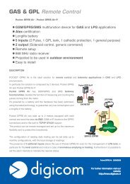
Output DimensionsAD 047ADR 047ADS 047AD 064 / AD 090ADR 064 / ADR 090ADS 064 / ADS 090AD 110ADR 110ADS 11045°1xD8 H74xD6ØD245°1xD8 H77xD61xD8 H7ØD222.5°22.5°11xD6ØD2ØD58xD10Ø D3 h7Ø D4 h7Ø D1 H78xD10ØD5ØD1 H7Ø D3 h7Ø D4 h7ØD58xD10Ø D3 h7Ø D4 h7ØD1 H7AD 140 / AD 200ADR 140 / ADR 200ADS 140 / ADS 200AD 255ADR 255ADS 2551xD8 H71xD8 H7ØD530°ØD211xD624°24°12xD6ØD2ØD5Ø D4 h712xD10Ø D4 h716xD10Ø D1 H7Ø D1 H7Ø D3 h7Ø D3 h7AD047 AD064 AD090 AD110 AD140 AD200 AD255ADR047ADR064ADR090ADR110ADR140ADR200ADR255ADS047ADS064ADS090ADS110ADS140ADS200ADS255D1 H7122031.5 40 50 80 100D22031.550 63 80 125 140D3 h7284063 80 100 160 180D4 h7476490 110 140 200 255D56779109 135 168 233 280D6M3 x 0.5PM5 x 0.8PM6 x 1P M6 x 1P M8 x 1.25P M10 x 1.5P M16 x 2PD8 H7356 6 8 10 12D103.44.55.5 5.5 6.6 9 13.5<strong>APEX</strong> 13
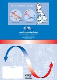
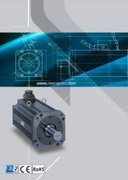
LXPermitted F Radial and Axial Loads on2 rInput Shaft of the ADS GearboxF 2aThe permitted radial and axial loads on input shaft of the gearboxdepend on the design of the gearbox supporting bearings.<strong>APEX</strong> use deep groove double roll ball bearing design.It can take heavy load from both axes.F Radial Load2rF Axial Load2aPermitted radial load F2rB[ N ]on center position of shaft13000120001100010000900080007000600050004000300020001000ADS047ADS064ADS090ADS110ADS140ADS200ADS255If radial force F exert on the2rcenter of the input shaftX=1/2 x L.Under various operatingcondition the lifetime is over30,000 hours.*The permitted radial load isgiven on left diagram.00100 200 300 400 500 600 700 800 900 1000 1100 1200130014001500160017001800190020002100Input Speed n [ rpm ]1Position load factor k b1.51.41.31.21.11.00.90.80.70.6ADS047ADS064ADS090ADS110ADS140ADS200ADS2550.50.40.30 20 40 60 80 120 180 200 260 320 400Position X [ mm ]*Continuous running reduces service life by 50%If radial force F not exert on2rthe center of the input shaftX1/2 x LThe permitted radial and axialload can be calculated by theposition load factor K on thebleft diagram.<strong>APEX</strong> 14
Ordering CodeAD SeriesAD047 010 P1Gearbox Size:AD047, AD064, AD090- - / MOTORAD110, AD140, AD200, AD255Backlash:P0: Micro BacklashP1: Reduced BacklashP2: Standard BacklashRatio:1 Stage: 4, 5, 7, 102 Stage: 20, 25, 35, 40, 50, 70, 10016, 21, 31, 61, 91Motor Designation:Manufacturer TypeAnd ModelOrdering Example: AD047-010-P1 / SIEMENS 1FT6 041-4AF71ADR SeriesADR047 - 010 - P1 / MOTORGearbox Size:ADR047, ADR064, ADR090ADR110, ADR140, ADR200, ADR255Backlash:P0: Micro BacklashP1: Reduced BacklashP2: Standard BacklashRatio:1 Stage: 4, 5, 7, 10, 14, 202 Stage: 20, 25, 35, 40, 50, 70, 100, 140, 200Motor Designation:Manufacturer TypeAnd ModelOrdering Example: ADR047-010-P1 / SIEMENS 1FT5 034-OAK71ADS Series- - -ADS047 010 S1P1Gearbox Size:ADS047, ADS064, ADS090ADS110, ADS140, ADS200, ADS255Shaft Option:S1: Smooth Input ShaftS2: Intput Shaft with KeyRatio:1 Stage: 4, 5, 7, 102 Stages: 16, 21, 31, 61, 91Backlash:P0: Micro BacklashP1: Reduced BacklashP2: Standard BacklashOrdering Example: ADS090-010-S1-P1Please visit our website for newest update data.<strong>APEX</strong> <strong>DYNAMICS</strong>, <strong>INC</strong>.No.10, Keyuan 3rd Rd., Situn District, Taichung City 407, Taiwan (R.O.C.)Tel: 886 4 23550219 / Fax: 886 4 23550218E-mail: sales@apexdyna.com / Website: www.apexdyna.com<strong>APEX</strong>-2009-10-AD / ADR / ADS-3.1V