AVR1907: Xplain Hardware User's Guide - Atmel Corporation
AVR1907: Xplain Hardware User's Guide - Atmel Corporation
AVR1907: Xplain Hardware User's Guide - Atmel Corporation
- No tags were found...

You also want an ePaper? Increase the reach of your titles
YUMPU automatically turns print PDFs into web optimized ePapers that Google loves.
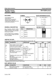
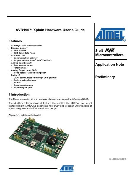
<strong>AVR1907</strong>: <strong>Xplain</strong> <strong>Hardware</strong> <strong>User's</strong> <strong>Guide</strong>Features• ATxmega128A1 microcontroller• External Memory- 8MB SDRAM- 8MB Serial Data Flash• AT90USB1287- Communication gateway- Programmer for <strong>Atmel</strong> ® AVR ® XMEGA• Analog Input (to ADC)- Temperature sensor- Potentiometer• Analog Output (from DAC)- Mono speaker via audio amplifier• Digital IO- UART communication through USB gateway- 8 micro switch buttons- 8 LEDs- 8 spare analog pins- 8 spare digital pins8-bitMicrocontrollersApplication NotePreliminary1 IntroductionThe <strong>Xplain</strong> evaluation kit is a hardware platform to evaluate the ATxmega128A1.The kit offers a larger range of features that enables the XMEGA user to getstarted using the XMEGA’s peripherals right away and to get an understanding ofhow to integrate the XMEGA in their own design.Figure 1-1. <strong>Xplain</strong> evaluation kit.Rev. 8203D-AVR-04/10
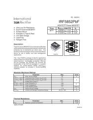
2 Related ItemsFLIP (Flexible In-System Programmer)http://www.atmel.com/dyn/products/tools_card.asp?tool_id=3886AVR Studio 4 (<strong>Atmel</strong>’s free IDE)http://www.atmel.com/dyn/products/tools_card.asp?tool_id=2725JTAGICE mkII (On-chip programming and debugging tool)http://www.atmel.com/dyn/products/tools_card.asp?tool_id=3353AVR ONE! (On-chip programming and debugging tool)http://www.atmel.com/dyn/products/tools_card.asp?tool_id=42793 General informationThis document targets the <strong>Xplain</strong> evaluation kit revision 3 and parts of the documentmay therefore be inconsistent with earlier revisions of the product. For earlier revisionplease refer to the schematics, which is this only documentation available for theserevision.The <strong>Xplain</strong> kit is intended to demonstrate the ATxmega128A1, and the hardware thatrelates to the AT90USB1287 is therefore not covered in this document.Figure 3-1. Overview of the <strong>Xplain</strong> kit.AT90USB1287 JTAG (J200)SDRAMATxmega128A1 JTAG (J100)DataFlashAudio amp.AT90USB1287SpeakerShunt resistorATxmega128A1XMEGA PORT A (J101)USB (COM and PSU)XMEGA PORT D (J102)3.1 Preprogrammed firmwareThe <strong>Xplain</strong> kit comes with both the ATxmega128A1 and the AT90USB1287preprogrammed.2 <strong>AVR1907</strong>The preprogrammed firmware in the XMEGA plays different sounds when the microswitch buttons are pushed.8203D-AVR-04/10
<strong>AVR1907</strong>The preprogrammed AT90USB1287 firmware offers features such as a bootloader forself-programming and a UART-to-USB gateway.3.2 Power supplyThe kit is powered from USB which leaves two options to power it: Either connectsthe kit to a PC through an USB cable, or to a 5V USB power supply (AC/DC adapter).3.3 Measuring the XMEGA power consumptionAs part of an evaluation of the ATxmega128A1 it can be of interest to measure itspower consumption. The R105 resistor (0 Ohm) is the only connection point betweenthe XMEGA power plane (the V_XM net) and common 3.3V supply of the board (theV3P3 net). By replacing the R105 shunt resistor with a higher value resistor it ispossible to determine the current consumption of the ATxmega128A1.3.4 Programming the XMEGA through the USB gateway3.5 Communication through UART-to-USB gatewayProgramming of the ATxmega128A1 through the USB is not supported in thepreliminary release.The XMEGA’s UARTC0 is connected to a software UART on the AT90USB1287. TheAT90USB1287 UART is communicating at 9600 baud, using one start bit, eight databits, one stop bit and no parity.When the AT90USB1287 device is enumerated (connected to a PC) the datatransmitted from the XMEGA is passed on to a (virtual) COM port. This means that itis possible to use a terminal program to receive the transmitted data on a PC.Similarly data transmitted from the PC COM port is passed on to the XMEGA UARTthrough the gateway.If the USB device is not enumerated, e.g. powering the kit from an USB supplyadapter, the AT90USB1287 device’s UART will operate in loop back mode (echoback everything it receives).4 ConnectorsThe <strong>Xplain</strong> kit has four 10-pin 100mill headers. Two are used for programming theATxmega128A1 and AT90USB1287, and two are to access spare analog and digitalpins on the XMEGA (expansion headers).4.1 Programming headersThe XMEGA can be programmed and debugged by connecting an externalprogramming/debugging tool to the “JTAG & PDI XMEGA” pin header (J100). The pinheader is having a standard JTAG programmer pinout (refer to online help in AVRStudio ® ), and tools like the JTAGICE mkII or the AVR ONE! can thus be connecteddirectly to the header. If it is desired to use PDI programming/debugging an adaptermust be used.8203D-AVR-04/103
Table 4-1. XMEGA programming and debugging interface – JTAG and PDI.J100 pin JTAG (1) PDI (2)J100-1 TCK -J100-2 GND GND (3)J100-3 TDO -J100-4 VCC VCC (3)J100-5 TMS -J100-6 nSRST CLKJ100-7 VCC VCC (3)J100-8 - DATAJ100-9 TDI -J100-10 GND GND (3)Notes:1. Standard pin-out for JTAGICE mkII and other <strong>Atmel</strong> programming tools.2. Requires adapter to connect a JTAGICE mkII (refer to AVR Studio help).3. It is only required to connect on VCC/GND pin.The AT90USB1287 can be programmed through its bootloader. The bootloader isevoked by shorting the (PORTF4) pin to GND before applying power to the board.This can be done by shorting pin 1 and 2 on the “JTAG USB” pin header (J200) with ajumper. Programming is performed through the “FLIP” plug-in in AVR Studio (can bestarted as a stand-alone application also).FLIP (FLexible In-system Programmer) is a free <strong>Atmel</strong>’s proprietary software that runsWindows ®9x/Me/NT/2000/XP and Linux x86. FLIP supports in-system programmingof Flash devices through RS232, USB or CAN.Alternatively, the AT90USB1287 can be also programmed by connecting aprogramming tool, such as a JTAGICE mkII, to the “JTAG USB” pin header (J200).Note that it is not recommended to program the AT90USB1287 using aprogramming tool as this will erase the bootloader.4.2 IO expansion headersThe XMEGA’s analog PORTA is available on the “XMEGA PORT A” pin header(J101). This allows the user to connect external signals to the ADC, DAC and AnalogComparators on PORTA.The XMEGA’s digital PORTD is available on the “XMEGA PORT D” pin header(J102). This port features general purpose IO and various communication modules(USART, SPI and TWI).Note that the communication modules on PORTD can be interconnected to test outvarious functions and features: The USART can loop back communication with ajumper, or communicate between the two UARTs on the PORT. The native SPI andthe USART in SPI master mode can be connected, and the TWI module can beenabled in both master and slave mode at the same time to get loop back behavior(pull-up resistors required).4 <strong>AVR1907</strong>8203D-AVR-04/10
5 Attached Memories<strong>AVR1907</strong>The <strong>Xplain</strong> kit demonstrates how to use the External Bus Interface (EBI) module tointerface a 4-bit SDRAM. An 8MB SDRAM (16M x 4) is attached in 3-port EBI mode(PORTH, PORTK and PORTJ).An 8MB serial Dataflash ®is connected to the UARTC1 which can operate in SPImaster mode to interface the dataflash.6 Miscellaneous IO6.1 Micro switch buttons6.2 LEDs6.3 Analog IOEight micro switch buttons are connected to the XMEGA’s PORTF. Internal pull-upsshould be enabled to detect when the buttons are pushed as they short the respectiveline to GND.Eight LEDs are connected to the XMEGA’s PORTE. The LEDs are active low – andthus lights up when the respective lines are drawn low by the XMEGA.An NTC and an adjustable resistor divider (potentiometer) are connected to PORTBon PINB0 and PINB1 respectively. These analog references can be used as input tothe ADC.An audio amplifier (and mono speaker) is connected to PORTB on PINB2. This pin isconnected to the XMEGA’s DAC and thus offers a way to generate sound.7 Available code examples and driversA Getting-Started training for the <strong>Xplain</strong> kit can be downloaded from the <strong>Atmel</strong> website. This training is a general introduction to XMEGA peripherals.Further information and drivers for XMEGA can be downloaded as application notes,also distributed from <strong>Atmel</strong>’s web site.8203D-AVR-04/105
8 Revision historyDifferent revisions of the <strong>Xplain</strong> kit is released, these revisions are not fully identical itcan therefore be relevant to identify the board used.8.1 Revision 1Revision 1 of the <strong>Xplain</strong> kit can be identified by not having a bar-code sticker on theback side.Table 8-1. <strong>Xplain</strong> revision 1 – known issues.Issue Cause SolutionSpeaker is noisy during programming anddebugging of the ATxmega128A1 whenusing JTAG.AT90USB1287 cannot connect to FLIPprogramming software to reprogram theAT90USB1287 application section of theflash.Problem due to cross-talk contaminatingthe audio amplifier input.No bootloader programmed in theAT90USB1287Use the PDI interface or remove resistorR305.Upgrade to the AT90USB1287 with thelatest firmware using an externalprogramming tool such as the JTAG ICEmkII.8.2 Revision 28.3 Revision 3Revision 2 of the <strong>Xplain</strong> kit can be identified by a bar-code sticker on the back sidewith the following product ID: A09-0560/2.Table 8-2. Difference between <strong>Xplain</strong> revision 1 and revision 2.DifferenceCommentDataflash changed to45DB642D-CNUThe 45DB642D-CNU is replacing the 45DB041D-SU.AT90USB1287 bootloader Bootloader is entered by shorting pin 1 and 2 on the J200.R305 removedTwo jumpers added –default placed on the J101and J102.To eliminate noise on speaker during JTAG programmingand debugging of the ATxmega128A1.For convenience of the end-user.Revision 3 of the <strong>Xplain</strong> kit can be identified by a bar-code sticker on the back sidewith the following product ID: A09-0560/3.Table 8-3. Difference between <strong>Xplain</strong> revision 2 and revision 3.DifferenceCommentSeries resistors on SDRAM Not required – and therefore removed.lines removedShunt resistor (R105) addedAudio amplifier is default off(R300 is pulling down theSD line of the U300).This is a zero ohm resistor that enables measurement of theATxmega128A1 current consumption.Reduce power consumption and reduce faint noise fromspeaker.6 <strong>AVR1907</strong>8203D-AVR-04/10
<strong>AVR1907</strong>8.4 Revision 4Revision 4 of the <strong>Xplain</strong> kit can be identified by a bar-code sticker on the back sidewith the following product ID: A09-0560/4.Table 8-4. Difference between <strong>Xplain</strong> revision 3 and revision 4.DifferenceCommentReplaced resistor R400 witha 0 ohm resistor.Reduce the noise on the power line but disable the <strong>Xplain</strong>board current measurement.78203D-AVR-04/10
DisclaimerHeadquartersInternational<strong>Atmel</strong> <strong>Corporation</strong>2325 Orchard ParkwaySan Jose, CA 95131USATel: 1(408) 441-0311Fax: 1(408) 487-2600<strong>Atmel</strong> AsiaUnit 1-5 & 16, 19/FBEA Tower, Millennium City 5418 Kwun Tong RoadKwun Tong, KowloonHong KongTel: (852) 2245-6100Fax: (852) 2722-1369<strong>Atmel</strong> EuropeLe Krebs8, Rue Jean-Pierre TimbaudBP 30978054 Saint-Quentin-en-Yvelines CedexFranceTel: (33) 1-30-60-70-00Fax: (33) 1-30-60-71-11<strong>Atmel</strong> Japan9F, Tonetsu Shinkawa Bldg.1-24-8 ShinkawaChuo-ku, Tokyo 104-0033JapanTel: (81) 3-3523-3551Fax: (81) 3-3523-7581Product ContactWeb Sitehttp://www.atmel.com/Technical Supportavr@atmel.comSales Contactwww.atmel.com/contactsLiterature Requestwww.atmel.com/literatureDisclaimer: The information in this document is provided in connection with <strong>Atmel</strong> products. No license, express or implied, by estoppel or otherwise, to anyintellectual property right is granted by this document or in connection with the sale of <strong>Atmel</strong> products. EXCEPT AS SET FORTH IN ATMEL’S TERMS ANDCONDITIONS OF SALE LOCATED ON ATMEL’S WEB SITE, ATMEL ASSUMES NO LIABILITY WHATSOEVER AND DISCLAIMS ANY EXPRESS, IMPLIEDOR STATUTORY WARRANTY RELATING TO ITS PRODUCTS INCLUDING, BUT NOT LIMITED TO, THE IMPLIED WARRANTY OF MERCHANTABILITY,FITNESS FOR A PARTICULAR PURPOSE, OR NON-INFRINGEMENT. IN NO EVENT SHALL ATMEL BE LIABLE FOR ANY DIRECT, INDIRECT,CONSEQUENTIAL, PUNITIVE, SPECIAL OR INCIDENTAL DAMAGES (INCLUDING, WITHOUT LIMITATION, DAMAGES FOR LOSS OF PROFITS,BUSINESS INTERRUPTION, OR LOSS OF INFORMATION) ARISING OUT OF THE USE OR INABILITY TO USE THIS DOCUMENT, EVEN IF ATMEL HASBEEN ADVISED OF THE POSSIBILITY OF SUCH DAMAGES. <strong>Atmel</strong> makes no representations or warranties with respect to the accuracy or completeness of thecontents of this document and reserves the right to make changes to specifications and product descriptions at any time without notice. <strong>Atmel</strong> does not make anycommitment to update the information contained herein. Unless specifically provided otherwise, <strong>Atmel</strong> products are not suitable for, and shall not be used in,automotive applications. <strong>Atmel</strong>’s products are not intended, authorized, or warranted for use as components in applications intended to support or sustain life.© 2010 <strong>Atmel</strong> <strong>Corporation</strong>. All rights reserved. <strong>Atmel</strong> ® , <strong>Atmel</strong> logo and combinations thereof, AVR ® , AVR ® logo, AVR Studio ® , DataFlash ® andothers, are the registered trademarks, XMEGA and others are trademarks of <strong>Atmel</strong> <strong>Corporation</strong> or its subsidiaries. Windows ® and others areregistered trademarks or trademarks of Microsoft <strong>Corporation</strong> in the US and/or other countries. Other terms and product names may betrademarks of others.8203D-AVR-04/10