read and save these instructions - Emerson Fans
read and save these instructions - Emerson Fans
read and save these instructions - Emerson Fans
- No tags were found...

Create successful ePaper yourself
Turn your PDF publications into a flip-book with our unique Google optimized e-Paper software.
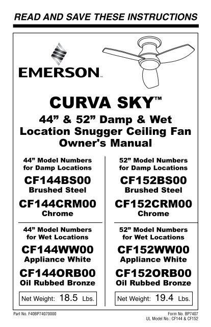
BP7407 44" & 52" Curva Sky 1/11/10 9:54 PM Page 1READ AND SAVE THESE INSTRUCTIONSCURVA SKY 44” & 52” Damp & WetLocation Snugger Ceiling FanOwner's Manual44” Model Numbersfor Damp LocationsCF144BS00Brushed SteelCF144CRM00Chrome44” Model Numbersfor Wet LocationsCF144WW00Appliance WhiteCF144ORB00Oil Rubbed BronzeNet Weight: 18.5 Lbs.52” Model Numbersfor Damp LocationsCF152BS00Brushed SteelCF152CRM00Chrome52” Model Numbersfor Wet LocationsCF152WW00Appliance WhiteCF152ORB00Oil Rubbed BronzeNet Weight: 19.4 Lbs.Part No. F40BP74070000Form No. BP7407UL Model No.: CF144 & CF152
BP7407 44" & 52" Curva Sky 1/11/10 9:54 PM Page 2! WARNINGWARNING: To avoid fire, shock, <strong>and</strong> serious personal injury, follow <strong>these</strong><strong>instructions</strong>.Safety Instructions1. Read your owner’s manual carefully <strong>and</strong> keep it for future reference.2. Before servicing or cleaning unit, switch power off at service panel <strong>and</strong> lock servicepanel disconnecting means to prevent power from being switched on accidentally.When the service disconnecting means cannot be locked, securely fasten awarning device, such as a tag, to the service panel.3. Be careful of the fan <strong>and</strong> blades when cleaning, painting, or working near the fan.Always turn off the power to the ceiling fan before servicing.4. Do not put anything into the fan blades while they are turning.Additional Safety Instructions for Installation1. To avoid possible shock, be sure electricity is turned off at the fuse box beforewiring, <strong>and</strong> do not operate fan without blades.2. The installation is to be in accordance with the National Electrical Code, ANSI/NFPA70-2008 <strong>and</strong> Local Codes. Use the National Electrical Code if Local Codes do notexist. The ceiling fan must be grounded as a precaution against possible electricalshock. Electrical installation should be made or approved by a licensed electrician.3. The outlet box <strong>and</strong> joist must be securely mounted <strong>and</strong> capable of reliablysupporting at least 50 pounds. Use only U.L. outlet boxes listed as “Acceptable forFan Support”, <strong>and</strong> use the mounting screws provided with the outlet box. Mostoutlet boxes commonly used for support of light fixtures are notacceptable for fan support <strong>and</strong> may need to be replaced. Consult a qualifiedelectrician if in doubt.4. The fan must be mounted with the fan blades at least 7 feet from the floor to preventaccidental contact with the fan blades.5. Follow the recommended <strong>instructions</strong> for the proper method of wiring your ceilingfan. If you do not know enough about electrical wiring, have your fan installed by alicensed electrician.NOTE: This fan is suitable for use with solid-state speed controls.WARNING: To reduce the risk of fire or electric shock, this fan should only be usedwith fan speed control Model No. UC8013G, manufactured by Rhine Electric Co., Ltd.WARNING: This product is designed to use only those parts supplied with thisproduct <strong>and</strong>/or any accessories designated specifically for use with this product by<strong>Emerson</strong> Electric Co. Substitution of parts or accessories not designated for use withthis product by <strong>Emerson</strong> Electric Co. could result in personal injury orproperty damage.WARNING: To reduce the risk of personal injury, do not bend the blade flange wheninstalling the blade flanges, balancing the blades or cleaning the fan. Do not insertforeign objects in between rotating fan blades.WARNING: To reduce the risk of electric shock, this fan must be installed with anisolating remote control/switch.DATE CODE:The date code of this fan may be found on the box, stamped in ink on a white label.You should record this data above <strong>and</strong> keep it in a safe place for future use.2 UL Model No.: CF144 & CF152
BP7407 44" & 52" Curva Sky 1/11/10 9:54 PM Page 3THE FAN MODELS CF144BS, CF144CRM, CF152BS & CF152CRM ARE SUITABLEFOR DAMP LOCATIONS SUCH AS COVERED PORCHES, COVERED PATIOS,AND COVERED DECKS...ANYWHERE THERE IS A ROOF OVERHEAD.THE FAN MODELS CF144WW, CF144ORB, CF152WW & CF152ORB ARESUITABLE FOR WET LOCATIONS SUCH AS PORCHES, PATIOS, AND DECKS.This Manual is Designed to Make it as Easy as Possible for You toAssemble, Install, Operate <strong>and</strong> Maintain Your Ceiling FanTools Needed for AssemblyOne Phillips head screwdriverOne wire stripperOne stepladderInstalled Wire Length Wire Size A.W.G.Up to 50 ft. 1450-100 ft. 12MaterialsWiring, outlet box <strong>and</strong> box connectorsmust be of type required by the local code.The minimum wire would be a 3-conductor(2-wire with ground) of the following sizes:! WARNINGBefore assembling your ceiling fan, referto section on proper method of wiringyour fan (Page 7). If you feel you do nothave enough wiring knowledge orexperience, have your fan installed by alicensed electrician.! WARNINGDo not install or use fan if any part isdamaged or missing. Call Toll-Free:1-800-654-3545! WARNINGThis product is designed to use onlythose parts supplied with this product<strong>and</strong>/or any accessories designatedspecifically for use with this product by<strong>Emerson</strong> Electric Co. Substitution ofparts or accessories not designated foruse with this product by <strong>Emerson</strong> ElectricCo. could result in personal injury orproperty damage.Unpacking InstructionsFor your convenience, check-off boxes are provided next to each step. As eachstep is completed, place a check mark in the box. This will insure that all stepshave been completed <strong>and</strong> will be helpful in finding your place should you beinterrupted.1. Open carton containing fan. Removetop half of styrofoam unit. Removeparts <strong>and</strong> check to see that you havereceived the following parts:NOTE: If you are uncertain of partdescription, refer to exploded viewillustration.a. Fan motor assemblyb. One ceiling trim ringc. One ceiling mounting plated. Three fan bladese. One lower housingf. One light kit plateg. One glass shadeh. One no-light cover platei. One 6-speed electronic receivercontrol with parts bagj. One 6-speed h<strong>and</strong>held transmitterwith wall bracketk. Two 50W halogen mini c<strong>and</strong>elabrabulbsl. One loose parts bag containing:1. Three 12 ga. wire connectors2. One spare M5 x 10mm pan headceiling cover screw3. Ten M5 x 16mm flange headblade screws4. One spare M4 x 10mm pan headscrew for lower housing <strong>and</strong>light kit5. One balancing kit3UL Model No.: CF144 & CF152
BP7407 44" & 52" Curva Sky 1/11/10 9:54 PM Page 4A. FAN MOTORASSEMBLYB. CEILINGTRIM RINGE. LOWERHOUSINGC. CEILINGMOUNTING PLATEF. LIGHTKIT PLATEH. NO-LIGHTCOVER PLATED. FAN BLADES (3)K. 50W MINI CANDELABRAHALOGEN BULBSG. GLASS SHADEI. 6-SPEEDELECTRONICRECEIVERJ. 6-SPEEDHANDHELDTRANSMITTERL. LOOSEPARTS BAGNOTE: Place the parts from the looseparts bags in a small container to keepthem from being lost.PROTECTIVEPLASTIC BAG2. Remove the fan motor assembly fromthe protective plastic bag. Place allcarton contents on a protectivesurface.4UL Model No.: CF144 & CF152
BP7407 44" & 52" Curva Sky 1/11/10 9:54 PM Page 5Electrical RequirementsIMPORTANT: Your ceiling fan will notfunction properly, <strong>and</strong> may bedamaged, if used with any wall dimmerswitch or control other than the<strong>Emerson</strong> Electric Fan/Light RemoteControl supplied with the fan.Your new ceiling fan will require agrounded electrical supply line of 120 voltsAC, 60 Hz, 15 amp circuit.The outlet box must be securely anchored<strong>and</strong> capable of withst<strong>and</strong>ing a load of atleast 50 pounds.! WARNINGTo reduce the risk of fire, electric shock,or personal injury, mount fan to outlet boxmarked “Acceptable for Fan Support”,<strong>and</strong> use screws supplied with outlet box.Most outlet boxes commonly used forsupport of light fixtures are notacceptable for fan support <strong>and</strong> may needto be replaced. Consult a qualifiedelectrician if in doubt.If your fan is to replace an existing ceilinglight fixture, turn electricity off at the mainfuse or circuit breaker box at this time <strong>and</strong>remove the existing light fixture.! WARNINGTurning off wall switch is not sufficient.To avoid possible electrical shock, besure electricity is turned off at the mainfuse or circuit breaker box before wiring.All wiring must be in accordance withNational <strong>and</strong> Local codes <strong>and</strong> the ceilingfan must be properly grounded as aprecaution against possible electricalshock.How to Assemble YourCeiling Fan1. Position the fan motor assembly upsidedown in preparation for mounting thethree fan blades.2. Slide blade through blade slot in fanhousing assembly. Mount blade to fanhousing using three M5 x 16mm flangehead blade screws (Figure 1).NOTE: Take care not to scratch fanhousing assembly when installingblades.FANBLADESLIDE FAN BLADEINTO BLADECENTER SLOTFigure 1BLADESLOTM5 x 16mm FLANGEHEAD BLADE SCREWS(3 per blade)FANHOUSING3. Complete the remaining two bladesinstallation per the above <strong>instructions</strong>.4. Remove one of the three screws in themotor housing assembly <strong>and</strong> loosenthe remaining two screws (Figure 2).5. Attach the lower housing assembly tothe fan motor using the two key slotholes (Figure 2). Secure the lowerhousing assembly by tightening the twoscrews. Reinstall the screw that waspreviously removed.REMOVE M4 x 10mmPAN HEAD SCREWLOWER HOUSINGCeiling Fan ProceduresGeneralYour <strong>Emerson</strong> ceiling fan comes suppliedwith a Fan/Light Remote Control whichconsists of a receiver mounted inside theceiling cover of the fan motor housing.This system allows you to regulate yourceiling fan speed <strong>and</strong> light intensity.5Figure 2KEY HOLESLOT (2)UL Model No.: CF144 & CF152
BP7407 44" & 52" Curva Sky 1/11/10 9:54 PM Page 66. Remove <strong>and</strong> retain the wire connectorsfrom the white <strong>and</strong> blue wires.7. Connect the white wire from the ceilingfan to the white wire of the light kit plate(Figure 3). Connect the blue wire fromthe ceiling fan to the black wire of thelight kit plate. Use wire connectors(previously removed) to makeconnections.8. Remove one of the three screws in thelower housing <strong>and</strong> loosen theremaining two screws (Figure 3).LIGHT KITBLACK WIRELIGHT KITWHITE WIREREMOVE ONELOWER HOUSINGSCREWATLEAST7'How to HangYour Ceiling Fan! WARNINGThe fan must be hung with at least 7' ofclearance from floor to blades (Figure 5).CEILINGFigure 39. Tuck the wires <strong>and</strong> connectors into thefan housing. Position the light kit plateinto the fan housing by placing the cutout notches over the fan housingdimples (Figure 4).NOTE: Make sure all wires <strong>and</strong>connectors are tucked under the lightkit plate <strong>and</strong> not pinched between lightkit plate <strong>and</strong> fan housing.10. Attach the light kit plate assembly tothe lower housing using two key slotholes (Figure 4). Secure the light kitplate assembly by tightening the twoscrews. Reinstall the screw that waspreviously removed.Figure 4FAN MOTORBLUE WIREFAN MOTORWHITE WIRELOWER HOUSINGKEY HOLE SLOT (2)REMOVE M4 x 10mmPAN HEAD SCREWCUT OUTNOTCHESDIMPLESLIGHT KITPLATEFigure 5FLOOR! WARNINGThe outlet box <strong>and</strong> joist must be securelymounted <strong>and</strong> capable of supporting atleast 50 lbs. Use only a U.L. outlet boxlisted as “Acceptable for Fan Support”.! WARNINGTo reduce the risk of fire, electric shock,or personal injury, mount fan to outlet boxmarked “Acceptable for Fan Support”,<strong>and</strong> use screws supplied with outlet box.Most outlet boxes commonly used forsupport of light fixtures are notacceptable for fan support <strong>and</strong> may needto be replaced. Consult a qualifiedelectrician if in doubt.1. Disconnect electrical power to the branchcircuit at the circuit breaker or fuse boxbefore attempting to install the ceiling fanmounting plate on the outlet box.! WARNINGTurning off wall switch is not sufficient.To avoid possible electrical shock, be sureelectricity is turned off at the main fuse orcircuit breaker box before wiring. All wiringmust be in accordance with National <strong>and</strong>Local codes <strong>and</strong> the ceiling fan must beproperly grounded as a precaution againstpossible electrical shock.6 UL Model No.: CF144 & CF152
BP7407 44" & 52" Curva Sky 1/11/10 9:54 PM Page 72. Pull the electrical supply black, white<strong>and</strong> ground wires through the centeropening of the ceiling mounting platebefore securing the plate to the outletbox (Figure 6).3. Position the ceiling mounting plate ontothe outlet box <strong>and</strong> secure using the twooutlet box screws, supplied with outletbox (Figure 6).OUTLETBOXCEILINGMOUNTINGPLATEHow to WireYour Ceiling FanIf you feel that you do not have enoughelectrical wiring knowledge orexperience, have your fan installed by alicensed electrician.! WARNINGTurning off wall switch is not sufficient.To avoid possible electrical shock, besure electricity is turned off at the mainfuse box before wiring. All wiring must bein accordance with National <strong>and</strong> Localcodes <strong>and</strong> the ceiling fan must beproperly grounded as a precautionagainst possible electrical shock.Figure 6OUTLET BOXSCREWS (2)CEILINGMOUNTINGPLATE HOOKCAUTION: To reduce the risk of electricalshock, disconnect the electrical supplycircuit before installing the fan, light kitor receiver.4. Slide the ceiling trim ring over the fanmotor assembly <strong>and</strong> let it rest on themotor assembly (Figure 7).FAN MOTORASSEMBLYCEILINGTRIMRINGFigure 75. Place the motor assembly onto theceiling mounting plate hook duringwiring fan motor assembly to outlet box(Figure 8).CEILINGMOUNTINGPLATEFAN MOTORASSEMBLYFigure 8HOOKNOTE: Make all wiring connectionsusing wire connectors (supplied). Makesure that all connections are tight,including ground, <strong>and</strong> that no bare wireis visible at the wire connectors, exceptfor the ground wire.1. Position the receiver into the fan motorhousing as shown in Figure 9.2. Refer to Figures 9 <strong>and</strong> 10 to connectthe receiver wires to the supply wires<strong>and</strong> the fan motor wires using the wireconnectors supplied with the fan asfollows:a. Securely connect the green groundingwire from the ceiling mounting plate tothe supply green grounding conductor(this may be a bare wire or a wire withgreen insulation).b. Securely connect the supply white(neutral) wire to the receiver white(AC IN N)/(TO MOTOR N) wire <strong>and</strong>white (neutral) fan wire.c. Securely connect the supply black wireto the receiver black/white (AC IN L)wire.d. Securely connect the fan motor blackwire to the receiver black (TO MOTORL) wire.e. Securely connect the fan motor bluewire to the receiver blue (FORBOTTOM LIGHT) wire.7 UL Model No.: CF144 & CF152
BP7407 44" & 52" Curva Sky 1/11/10 9:54 PM Page 8Check to see that all connections aretight, including ground, <strong>and</strong> that no barewire is visible at the wire connectors,except for the ground wire. Do notoperate fan until blades are in place.Noise <strong>and</strong> fan damage could result.ANTENNAWIREFigure 9WHITERECEIVERWIREBLACK RECEIVERWIREBLACK/WHITERECEIVER WIREFigure 10WHITE FAN WIRE! WARNINGBLACK FAN WIRESUPPLY & CEILING MOUNTINGPLATE GREEN WIRESSUPPLY,RECEIVER & FANWHITE WIRESSUPPLYBLACK WIRERECEIVERBLACK/WHITEWIREFAN &RECEIVERBLUE WIRESFAN BLACKWIRERECEIVERBLACK SUPPLYWIRERECEIVER BLACKWIRERECEIVERWHITESUPPLYWIREBLUE RECEIVERWIREBLUE FAN WIRE3. After connections have been made,turn leads upward <strong>and</strong> carefully pushleads into the outlet box, with the white<strong>and</strong> green leads on one side of theoutlet box <strong>and</strong> the black <strong>and</strong> blue leadson the other inside of the outlet box.! WARNINGTo avoid possible fire or shock, makesure that the electrical wires arecompletely inside the outlet box <strong>and</strong>not pinched between the ceilingmounting plate <strong>and</strong> the fan motorhousing assembly.4. Remove one of the four screws in theceiling mounting plate <strong>and</strong> loosen theremaining three screws (Figure 11).5. Unhook the fan motor housing from theceiling mounting plate hook <strong>and</strong> lift thefan motor housing assembly up to theceiling mounting plate. Align <strong>and</strong>engage the motor assembly slots withthe three screw heads previouslyloosened by rotating the fan motorhousing assembly clockwise. Install thepreviously removed M5 x 10mm screw<strong>and</strong> secure the assembly to the plate(Figure 11). Completely tighten all fourscrews.Figure 11CEILINGMOUNTING PLATEM5 x 10mm PANHEAD CEILINGCOVER SCREWSFAN MOTORHOUSINGASSEMBLY6. Position the ceiling trim ring over eachof the protruding ceiling cover screwheads <strong>and</strong> rotate the ceiling trim ringclockwise to secure (Figure 12).CEILING COVER SCREWHEADS (4)CEILINGTRIM RINGFAN MOTORHOUSINGASSEMBLYFigure 128UL Model No.: CF144 & CF152
BP7407 44" & 52" Curva Sky 1/11/10 9:54 PM Page 9How to Assemble YourLight Kit Glass Shade1. Screw in two 50-watt (maximum)halogen mini c<strong>and</strong>elabra base bulbs inthe light kit plate sockets (Figure 13).50-WATT (maximum)HALOGEN MINICANDELABRA BASEBULBS (2)Figure 13LIGHT KIT PLATESOCKETS (2)2. Place the glass shade into the openingin the fan motor housing assembly,aligning the three flat areas on the topedge of the glass with the three raiseddimples on the fan motor housingassembly <strong>and</strong> turn the glass shadeclockwise until it stops (Figure 14).NOTE: periodically check that the glassshade is seated fully clockwise in thefan motor housing assembly.How to Assemble YourNo Light Cover Plate! WARNINGDo not install any light bulbs into thelight kit plate if using the cover plate.Installation of light bulbs when usingthe cover plate could result in fire,shock <strong>and</strong> serious personal injury.1. Place the cover plate onto the lowerhousing aligning the three flat areas onthe top flange of the cover plate withthe three pins on the inside of the fanmotor housing assembly (Figure 15).Then turn the cover plate clockwiseuntil it stops turning.2. Your cover plate is now installedDO NOT INSTALL LIGHT BULBSWHEN USING THE COVER PLATEDIMPLES (3)FLAT AREA (3)COVERPLATEFigure 15DIMPLES (3)FLAT AREA (3)GLASSBOWLFigure 149UL Model No.: CF144 & CF152
BP7407 44" & 52" Curva Sky 1/11/10 9:54 PM Page 10REMOTE CONTROLPROCEDURESGeneralYour <strong>Emerson</strong> Ceiling Fan/Light RemoteControl consists of h<strong>and</strong>-held transmitter<strong>and</strong> a receiver which is mounted under thefan ceiling cover. The remote control isdesigned to separately control your ceilingfan speed <strong>and</strong> light intensity.The remote control transmitter is poweredby two AAA alkaline batteries (included).To prevent possible damage if thebatteries should leak, be sure to removethe batteries when the control is not to beused for an extended period of time.Code switches in the transmitter <strong>and</strong>receiver may be set in 32 differentpositions. If your fan <strong>and</strong> light go on <strong>and</strong>off without using your control, you may begetting interference from other remoteunits such as garage door openers, caralarms or security systems. To remedy thissituations, simply change the combinationcode in your transmitter <strong>and</strong> receiver.Preset Memory FeatureYour <strong>Emerson</strong> receiver is equipped with apreset memory feature. If the AC supply tothe receiver is powered through a wallswitch, when the switch is turned OFF, thecontrol will remember the light intensity<strong>and</strong> fan speed. When the switch is turnedback ON the light <strong>and</strong> fan will resumeoperation as they were prior to the switchbeing turned OFF.Installation of Battery1. Remove the battery cover by pressingfirmly below the arrow <strong>and</strong> sliding thecover off the control (Figure 16).2. Install two AAA alkaline batteries <strong>and</strong>reinstall the battery cover.TWO AAABATTERIESFigure 16BATTERYCOMPARTMENTCOVERREMOTE CONTROLLEVERSCODESWITCHESSR600 REMOTECONTROLON1 2 3 4 5 IInstallation of StorageBracket forRemote ControlA storage bracket is provided for holdingyour remote control when not in use. If youdesire to use the bracket, install it on awall that is away from excess heat orhumidity (Figure 17).TO INSTALL BRACKET TO WALL:SLIDE THE COVER UP TO EXPOSE THE SCREWHOLES FOR INSTALLATIONCOVERWALLBRACKETSCREWHOLES (2)Figure 1710 UL Model No.: CF144 & CF152
BP7407 44" & 52" Curva Sky 1/11/10 9:54 PM Page 11Setting OperatingFrequency ofRemote ControlYour remote control has code switcheswhich must be set in one of 32 possiblecode combinations (Figure 16). The fivelevers (numbered 1, 2, 3, 4, <strong>and</strong> 5) on theswitches are factory-set in the ON (up)position. Change the switch settings asfollows (Figure 18):1. Slide the five switch levers in theremote control to your choice of ON(up) or down positions. Use a ball-pointpen or small screwdriver <strong>and</strong> slide thelevers firmly up or down.2. When power is restored, push <strong>and</strong> holdthe fan OFF button ( ) for 3 to 5seconds to set the code in the receiver.3. If airflow is desired in the oppositedirection, press the ( ) button on theremote control. The fan must beoperating at any speed for the reversebutton to function. The blades will turnin the opposite direction <strong>and</strong> reversethe airflow.4. To set the desired fan speed, press the( ) button to decrease the speed <strong>and</strong>the ( ) to increase the speed. TheLED display will light up to indicate thenew speed selected.5. To turn the downlight on, press <strong>and</strong>release the ( ) button. The light willturn on at the light intensity previouslyselected.6. To vary the intensity of the light, holdthe ( ) button down until the desiredlight intensity is reached, then releasethe button.7. The sixth switch marked ON <strong>and</strong> I is fordimming control of lights: Set switch toON to allow for dimming of the lights.Set switch to I for no dimming of thelights such as for fluorescent bulbs.Figure 1811 UL Model No.: CF144 & CF152
BP7407 44" & 52" Curva Sky 1/11/10 9:54 PM Page 12MaintenanceIMPORTANT CARE INSTRUCTIONSfor your Ceiling FanPeriodic cleaning of your new ceiling fan isthe only maintenance that is needed.When cleaning, use only a soft brush orlint free cloth to avoid scratching the finish.Abrasive cleaning agents are not required<strong>and</strong> should be avoided to prevent damageto finish.! WARNINGDo not use water when cleaning yourceiling fan. It could damage the motor orthe blades <strong>and</strong> create the possibility of anelectrical shock.Accessories1. Downrod Extension Kits (see store orcatalog).2. Ceiling Fan Controls (see store orcatalog).! WARNINGThe use of any other control notspecifically approved for this fan couldresult in fire, shock <strong>and</strong> personal injury.! WARNINGThis product is designed to use onlythose parts supplied with this product<strong>and</strong>/or any accessories designatedspecifically for use with this product by<strong>Emerson</strong> Electric Co. Substitution ofparts or accessories not designated foruse with this product by <strong>Emerson</strong> ElectricCo. could result in personal injury orproperty damage.INSTRUCTION TO THE USER (if device contains a digital device)This equipment has been tested <strong>and</strong> found to comply with the limits for a class B digitaldevice, pursuant to part 15 of the FCC Rules. These limits are designed to provide reasonableprotection against harmful interference in a residential installation. This equipment generates,uses <strong>and</strong> can radiate radio frequency energy <strong>and</strong> if not installed <strong>and</strong> used in accordance withthe <strong>instructions</strong>, may cause harmful interference to radio communications. However, there isno guarantee that interference will not occur in a particular installation. If this equipment doescause harmful interference to radio or television reception, which can be determined byturning the equipment off <strong>and</strong> on, the user is encouraged to try to correct the interference byone or more of the following measures:• Reorient or relocate the receiving antenna.• Increase the separation between the equipment <strong>and</strong> receiver.• Connect the equipment into an outlet on a circuit different from that to which the receiveris connected.• Consult the dealer or an experienced radio/TV technician for help.This equipment has been certified to comply with the limits for a class B computing device,pursuant to FCC Rules. In order to maintain compliance with FCC regulations, shielded cablesmust be used with this equipment. Operation with non-approved equipment or unshieldedcables is likely to result in interference to radio <strong>and</strong> TV reception. The user is cautioned thatchanges <strong>and</strong> modifications made to the equipment without the approval of manufacturer couldvoid the user’s authority to operate this equipment.This Class B digital apparatus meets all requirements of the CanadianInterference-Causing Equipment Regulations.12UL Model No.: CF144 & CF152
BP7407 44" & 52" Curva Sky 1/11/10 9:54 PM Page 13Remote Control Trouble ShootingFan/Light Fails to Operate• Check that the speed switch on thefan is set to HIGH (....) speed.• Check that the light switch is on.• Check that the battery is good(red indicator light should light whenany button is pressed).• Check that the receiver is wiredproperly.• Check that code switches in theremote control <strong>and</strong> receiver are set inthe same position.Short Range• If the remote control operates the fanwhen close to it, but does not operateit at a distance of 40 feet, try placingthe antenna wire outside of the ceilingcover.! WARNING: FOR YOUR OWN SAFETY TURN OFF POWER AT FUSE BOXOR CIRCUIT BREAKER BEFORE TROUBLE SHOOTING YOUR FAN.Ceiling Fan Trouble ShootingTROUBLE PROBABLE CAUSE SUGGESTED REMEDY1. Fan will not 1. Fuse or circuit breaker 1. Check main <strong>and</strong> branchstart. blown. circuit fuses or circuit breakers.! WARNING: Make suremain power is turned off.2. Loose power line 2. Check line power connectionsconnections to the fan.to fan.3. Fan/Light remote control is OFF. 3. Turn ON Fan/Light remote control.2. Fan sounds 1. Blades not attached to fan. 1. Attach blades to fan beforenoisy.operating.2. Screws securing fan blades 2. Check to make sure the screwsto motor are loose.which attach the blades to themotor are tight.! WARNING: Make sure mainpower is turned off.3. Fan wobbles 1. Screws securing fan blades 1. Check to be sure screws whichexcessively. to motor are loose. attach the fan blade to themotor are tight.2. Fan blades are not seated 2. Check to be sure that theproperly.screws securing the fanblades seat firmly.3. Fan blades out of balance. 3. Interchanging an adjacent (sideby-side) blade pair canredistribute the weight <strong>and</strong> resultin smoother operation.Or use supplied balancing kit tobalance blades.13UL Model No.: CF144 & CF152
BP7407 44" & 52" Curva Sky 1/11/10 9:54 PM Page 14Repair Parts ListingDamp Part NumbersWet Part NumbersKey Model No. Model No. Model No. Model No. Model No. Model No. Model No. Model No.No. Description CF144BS00 CF152BS00 CF144CRM00 CF152CRM00 CF144WW00 CF152WW00 CF144ORB00 CF152ORB001 Ceiling Mounting Plate 763987 763987 763987 763987 763987 763987 763987 7639872 Ceiling Trim Ring 763989-BS 763989-BS 763989-CRM 763989-CRM 763989-WW 763989-WW 763989-ORB 763989-ORB3 Ceiling Cover 763988-BS 763988-BS 763988-CRM 763988-CRM 763988-WW 763988-WW 763988-ORB 763988-ORB4 Lower Housing 763992-BS 763992-BS 763992-CRM 763992-CRM 763992-WW 763992-WW 763992-ORB 763992-ORB5 Light Kit Plate Assembly 764006 764006 764006 764006 764006 764006 764006 7640066 Glass Shade 763994-OM 763994-OM 763994-OM 763994-OM 763994-OM 763994-OM 763994-SST 763994-SST7 No Light Kit Cover 763995-BS 763995-BS 763995-CRM 763995-CRM 763995-WW 763995-WW 763995-ORB 763995-ORB8 52” Blade Assembly — 763996-BS — 763996-BS — 763996-WW — 763996-ORB9 44” Blade Assembly 763998-BS — 763998-BS — 763998-WW — 763998-ORB —10 Harness, Wiring 764007 764007 764007 764007 764007 764007 764007 76400711 H<strong>and</strong>held Transmitter 763979 763979 763979 763979 763979 763979 763979 76397912 Electronic Receiver withWire Connectors 764009 764009 764009 764009 764009 764009 764009 764009* Parts Bag, Containing: 764008 764008 764008 764008 764008 764008 764008 76400813 Connector, Wire, 12 Ga. (3) — — — — — — — —14 Screw, Pan Head, CeilingCover, M5 x 10mm (1) — — — — — — — —15 Screw, Flange Head, BladeM5 x 16mm (10) — — — — — — — —16 Screw, Serrated Head, LowerHousing/Light Kit,M4 x 10mm (1) — — — — — — — —17 Kit, Balancing — — — — — — — —— Owner's Manual BP7407 BP7407 BP7407 BP7407 BP7407 BP7407 BP7407 BP740714 UL Model No.: CF144 & CF152
BP7407 44" & 52" Curva Sky 1/11/10 9:54 PM Page 15Repair Parts1142173138 - 52"9 - 44"16105541511612Before discarding packaging material, be certain all parts have been removed.HOW TO ORDER REPAIR PARTSWHEN ORDERING REPAIR PARTS, ALWAYS GIVE THE FOLLOWING INFORMATION:• PART NUMBER• NAME OF ITEM• PART DESCRIPTION• MODEL NUMBERThe model number of your Fan will be found on a label attached to the top housing.For repair parts, phone 1-800-654-3545.15 UL Model No.: CF144 & CF152
BP7407 44" & 52" Curva Sky 1/11/10 9:54 PM Page 16LIMITED WARRANTYWhat The Warranty Covers:This warranty covers the motor <strong>and</strong> the other components <strong>and</strong> accessories of your <strong>Emerson</strong> ceiling fan against all defects inworkmanship <strong>and</strong> materials. You must be the original purchaser or user of the product to be covered.What The Period Of Coverage Is:As it applies to the motor, this warranty will last for the lifetime of your ceiling fan. All other components <strong>and</strong> accessories arecovered by this warranty for one year from the date you purchased your ceiling fan. ANY IMPLIED WARRANTY OFMERCHANTABILITY OR FITNESS FOR A PARTICULAR PURPOSE, MADE WITH RESPECT TO COMPONENTS ANDACCESSORIES IS ALSO LIMITED TO ONE YEAR.What Will <strong>Emerson</strong> Electric Co. Do To Correct Problems:<strong>Emerson</strong> Electric Co. will replace a defective <strong>Emerson</strong> Air Comfort Ceiling Fan motor, blade, component or other accessory atno charge to you. If repair of the motor or blades is not practical or possible within a reasonable time <strong>and</strong> no replacement canbe provided, <strong>Emerson</strong> will refund the actual purchase price of your fan. WE WILL SHIP THE REPAIRED PRODUCT ORREPLACEMENT TO YOU AT NO CHARGE, BUT YOU ARE RESPONSIBLE FOR ALL COSTS OR REMOVAL, REINSTALLATIONAND SHIPPING OF THE PRODUCT TO EMERSON ELECTRIC CO.How Can You Get Service:YOU MUST HAVE PROOF OF YOUR PURCHASE OF THE CEILING FAN TO OBTAIN LIMITED WARRANTY SERVICE. KEEP YOURRECEIPT OR OTHER PROOF OF PURCHASE. You can return the product to our factory or to your nearest authorized servicecenter.• To return the product to the factory, obtain a return authorization <strong>and</strong> service identification tag by writing to Air ComfortProducts, Division of <strong>Emerson</strong> Electric Electric Co., 8100 W. Florissant Ave., St. Louis, MO 63136. Include all modelnumbers shown on the product with your request.• To return the product to an authorized service center, call 1-800-654-3545 for the address of the nearest authorized servicecenter.You will be responsible for all insurance, freight or other transportation charges to our factory or authorized servicecenter. Your <strong>Emerson</strong> Air Comfort Ceiling Fan should be properly packed to avoid damage in transit since we will not beresponsible for any such damage.What Is Not Covered:The glass globes <strong>and</strong> light bulbs of your ceiling fan are not covered by this warranty. This warranty also does not cover anydefects, malfunctions or failures caused by:• Repairs by persons not authorized by <strong>Emerson</strong> Electric Co.,• Use of parts or accessories not authorized by <strong>Emerson</strong> Electric Co.,• Mish<strong>and</strong>ling, improper installation, modifications or damage to your ceiling fan while in your possession, or• Unreasonable use, misuse, abuse, including failing to do reasonable <strong>and</strong> necessary maintenance, <strong>and</strong> normal wear <strong>and</strong> tear.Additionally, this warranty <strong>and</strong> any implied warranty of merchantability or fitness for a particular purpose are voided when:• The original purchaser or user ceases to own the product, or• The fan is moved from its original point of installation.This warranty is only valid within the 50 states of the United States <strong>and</strong> the District of Columbia. No other written or oralwarranties apply, <strong>and</strong> no employee, agent, dealer or other person is authorized to give any warranties on behalf of <strong>Emerson</strong>Electric Co.REPAIR, REPLACEMENT OR A REFUND ARE THE EXCLUSIVE REMEDIES AVAILABLE UNDER THIS WARRANTY ANDEMERSON IS NOT RESPONSIBLE FOR DAMAGES OF ANY KIND, INCLUDING INCIDENTAL AND CONSEQUENTIAL DAMAGES.Incidental damages include but are not limited to such damages as loss of time <strong>and</strong> loss of use. Consequential damages includebut are not limited to the cost of repairing or replacing other property which was damaged if this product does not workproperly.How State Law Relates To The Warranty:Some states do not allow the exclusion or limitation of incidental or consequential damages so the above exclusion or limitationmay not apply to you. This warranty gives you specific legal rights, <strong>and</strong> you may also have other rights which vary from stateto state.Air Comfort ProductsDIVISION OF EMERSON ELECTRIC CO.8100 W. Florissant • St. Louis, MO 63136Part No. F40BP74070000 Printed in China 01/10 Form No. BP7407UL Model No.: CF144 & CF152