read and save these instructions - Emerson Fans
read and save these instructions - Emerson Fans
read and save these instructions - Emerson Fans
- No tags were found...

You also want an ePaper? Increase the reach of your titles
YUMPU automatically turns print PDFs into web optimized ePapers that Google loves.
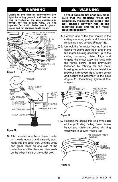
BP7407 44" & 52" Curva Sky 1/11/10 9:54 PM Page 8Check to see that all connections aretight, including ground, <strong>and</strong> that no barewire is visible at the wire connectors,except for the ground wire. Do notoperate fan until blades are in place.Noise <strong>and</strong> fan damage could result.ANTENNAWIREFigure 9WHITERECEIVERWIREBLACK RECEIVERWIREBLACK/WHITERECEIVER WIREFigure 10WHITE FAN WIRE! WARNINGBLACK FAN WIRESUPPLY & CEILING MOUNTINGPLATE GREEN WIRESSUPPLY,RECEIVER & FANWHITE WIRESSUPPLYBLACK WIRERECEIVERBLACK/WHITEWIREFAN &RECEIVERBLUE WIRESFAN BLACKWIRERECEIVERBLACK SUPPLYWIRERECEIVER BLACKWIRERECEIVERWHITESUPPLYWIREBLUE RECEIVERWIREBLUE FAN WIRE3. After connections have been made,turn leads upward <strong>and</strong> carefully pushleads into the outlet box, with the white<strong>and</strong> green leads on one side of theoutlet box <strong>and</strong> the black <strong>and</strong> blue leadson the other inside of the outlet box.! WARNINGTo avoid possible fire or shock, makesure that the electrical wires arecompletely inside the outlet box <strong>and</strong>not pinched between the ceilingmounting plate <strong>and</strong> the fan motorhousing assembly.4. Remove one of the four screws in theceiling mounting plate <strong>and</strong> loosen theremaining three screws (Figure 11).5. Unhook the fan motor housing from theceiling mounting plate hook <strong>and</strong> lift thefan motor housing assembly up to theceiling mounting plate. Align <strong>and</strong>engage the motor assembly slots withthe three screw heads previouslyloosened by rotating the fan motorhousing assembly clockwise. Install thepreviously removed M5 x 10mm screw<strong>and</strong> secure the assembly to the plate(Figure 11). Completely tighten all fourscrews.Figure 11CEILINGMOUNTING PLATEM5 x 10mm PANHEAD CEILINGCOVER SCREWSFAN MOTORHOUSINGASSEMBLY6. Position the ceiling trim ring over eachof the protruding ceiling cover screwheads <strong>and</strong> rotate the ceiling trim ringclockwise to secure (Figure 12).CEILING COVER SCREWHEADS (4)CEILINGTRIM RINGFAN MOTORHOUSINGASSEMBLYFigure 128UL Model No.: CF144 & CF152