- Page 1 and 2:
European Co-operation in the Field
- Page 3 and 4:
Table of ContentsTable of ContentsE
- Page 5 and 6:
Chapter 4Chapter 4 : Pavement Wear
- Page 7 and 8:
Chapter 44.2 SCOPE OF THE WORKHisto
- Page 9 and 10:
Chapter 44.3 DEFINITION OF THE PROB
- Page 11 and 12:
Chapter 4It is observed 50 that the
- Page 13 and 14:
Chapter 4RimTyresFigure 4.4 - Tyre
- Page 15 and 16:
Chapter 4• Trucks may travel incr
- Page 17 and 18:
Chapter 4Table 4.2 - Length of Prim
- Page 19 and 20:
Chapter 4be noted that not all coun
- Page 21 and 22:
Chapter 4lesser effect than the loa
- Page 23 and 24:
Chapter 4(side view)1. load scaleor
- Page 25 and 26:
Chapter 44.3.4.4 The contact area s
- Page 27 and 28:
Chapter 4Figure 4.10 shows a simpli
- Page 29 and 30:
Chapter 4others). These different g
- Page 31 and 32:
Chapter 44.3.5.2 Pavement distress
- Page 33 and 34:
Chapter 44.3.6 Load effects4.3.6.1
- Page 35 and 36:
Chapter 4arrives within that period
- Page 37 and 38:
Chapter 4inflationdifferencepressur
- Page 39 and 40:
Chapter 4Mechanistic-empirical perf
- Page 41 and 42:
Chapter 4distressN2N1D1D2load cycle
- Page 43 and 44: Chapter 4pressure, diameter, contac
- Page 45 and 46: Chapter 4Table 4.10 - Summary of re
- Page 47 and 48: Chapter 4Table 4.11 - Properties of
- Page 49 and 50: Chapter 4difference in tyre pressur
- Page 51 and 52: Chapter 4Table 4.14 - Footprint wid
- Page 53 and 54: Chapter 4• Drive axle, twin tyres
- Page 55 and 56: Chapter 4for a given rim diameter,
- Page 57 and 58: Chapter 4Figure 4.21- Setup for whe
- Page 59 and 60: Chapter 4Table 4.17 - Unequal load
- Page 61 and 62: Chapter 44.4.9.3 Tekscan Measuremen
- Page 63 and 64: Chapter 4Figure 4.30 - 295/60R22.5
- Page 65 and 66: Chapter 4The following conclusions
- Page 67 and 68: Chapter 4An extensive identificatio
- Page 69 and 70: Chapter 4different diameter tyres.
- Page 71 and 72: Chapter 4pavement surface, for the
- Page 73 and 74: Chapter 4Table 4.21 - Maximum subgr
- Page 75 and 76: Chapter 44.50Initial readings amend
- Page 77 and 78: Chapter 42.0m 3.5m 2.0m 2.0m 3.5m2.
- Page 79 and 80: Chapter 4• the maximum rut depth
- Page 81 and 82: Chapter 4measurements but needs fur
- Page 83 and 84: Chapter 4Figure 4.47 - Manège de F
- Page 85 and 86: Chapter 4(0.48 m depth) and near th
- Page 87 and 88: Chapter 4this question was to compa
- Page 89 and 90: Chapter 4The conclusion of the anal
- Page 91 and 92: Chapter 46050Stress [kPa]403020100B
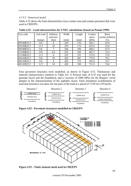
- Page 93: Chapter 4Length contact areaDirecti
- Page 97 and 98: Chapter 4Table 4.33 - Practical per
- Page 99 and 100: Chapter 4Practical permanent deform
- Page 101 and 102: Chapter 4• “Pressure ratio” i
- Page 103 and 104: Chapter 4also may be that the param
- Page 105 and 106: Chapter 41.21.0Ln Distress ratio pr
- Page 107 and 108: Chapter 44.5.10.7 Regression result
- Page 109 and 110: Chapter 44.5.10.8 Summary and concl
- Page 111 and 112: Chapter 44.6 EFFECTS OF UNEQUAL LOA
- Page 113 and 114: Chapter 4• Molzer used worst-case
- Page 115 and 116: Chapter 4Table 4.43 - Vertical subg
- Page 117 and 118: Chapter 4Table 4.47 - Practical per
- Page 119 and 120: Chapter 42544 km (divided over 1998
- Page 121 and 122: Chapter 44.7 EFFECTS OF DYNAMICS4.7
- Page 123 and 124: Chapter 43. Measurements of dynamic
- Page 125 and 126: Chapter 4Figure 4.65 - Truck tyre o
- Page 127 and 128: Chapter 4road. The results of the D
- Page 129 and 130: Chapter 4Table 4.55 - Calculated st
- Page 131 and 132: Chapter 4The wide base single tyre
- Page 133 and 134: Chapter 4In the two tables below th
- Page 135 and 136: Chapter 44.8.3 Evaluation and sensi
- Page 137 and 138: Chapter 4fatigue• The total conta
- Page 139 and 140: Chapter 4Like for the towed axles,
- Page 141 and 142: Chapter 4Table 4.66 - Overview of a
- Page 143 and 144: Chapter 44.8.6 Specification of roa
- Page 145 and 146:
Chapter 4Table 4.67 Values of Axle
- Page 147 and 148:
Chapter 4Table 4.70 Proposed TCF li
- Page 149 and 150:
Chapter 44.9 SUMMARY, CONCLUSIONS A
- Page 151 and 152:
Chapter 4values were calculated as
- Page 153 and 154:
Chapter 4334 established good techn
- Page 155 and 156:
Chapter 4The development of the Tyr
- Page 157 and 158:
Chapter 4• From the same viewpoin
- Page 159 and 160:
Chapter 4DBMdistressDLCdouble axled
- Page 161 and 162:
Chapter 4pavementPCCperformanceperm
- Page 163 and 164:
Chapter 4tandem axleTCFtfthermal cr
- Page 165 and 166:
Chapter 44.11 REFERENCESAddis RR (1
- Page 167 and 168:
Chapter 4rutting from new single ty
- Page 169 and 170:
Chapter 4Molzer C (1998) Revision o