5. Aerator with Optional Stand or Draft TubeThere may be a need to install the aerator at a deeper position than its MWD, for example;· An aerator is going to be installed in an existing tank, and it is not possible to alter the depth of the tank, and· Because of the limited surface area, the tank must be designed to have a greater depth, etc.Adoption of a <strong>Tsurumi</strong> aerator with optional stand or draft tube (DT) will be one of the solutions for these cases. In case ofusing a stand, the mixing force at the bottom will be weakened as the inlet port of the aerator moves away from the bottom.Therefore, we have set the height limit on the stand of 0.5 meters, and for the cases of more than 0.5meters are required,we recommend an aerator with a DT. Note that the oxygen transfer rate and the air flow rate of the aerator shall be thosethat are obtainable at its self-aspiration water depth d [installation water depth h – (minus) height of stand or DT]. Inaddition, it shall be noted that the performance of the aerator with DT can be slightly lower than that of the standard.When there is a fear of overload occurring to the motor by due to a reason that it is going to operate in a viscous liquid, etc.,it will be possible to prevent the overload by reducing the self-aspiration water depth d with this method.The aerator may move or fall during operation by a reason that it is sitting on an irregular floor like slanted, bumpy, orslippery floor, or by a reason that it is installed in such that the weight of air-inlet piping acts on the aerator. Take anappropriate preventive measure in accordance with the conditions. In case that there is any flow generating equipment inthe tank, the same measure must be required.InstallationWater Depth hDischarge CurrentSelf-aspirationWater Depth d(Within MWD)DischargeCurrentDischarge CurrentSuction CurrentWithOptional Stand/ DTSuctionCurrentSuctionCurrentWith a stand of 0.5mImage of 0.75kW(Available 0.75kW to 40kW)With a DT of 1.0mImage of 5.5kW(Available 22kW to 40kW)With a DT of 1.5mImage of 40kW(Available 24kW to 40kW)■ 5-1. Recommended Tank Dimensions (with Stand or Draft Tube)AirinletBore[mm]325080with Stand (0.5m) Draft Tube (1.0m) Draft Tube (1.5m)Dimension ofSub-convectionDimension ofSub-convectionDimension ofSub-convectionModelMax Installation Circular Square Installation Circular Square Installation Circular SquareMotorWater Water Tank Tank Water Tank Tank Water Tank TankOutputDepth Depth h φa a Depth h φa a Depth h φa a[kW][m] [m] [m] [m] [m] [m] [m] [m] [m] [m]32TRN2.75-52/62 0.75 3.5 4 3.5 332TRN21.5-52/62 1.5 3.5 4 4 3.550TRN42.2-52/62 2.2 3.6 4.1 5.5 5 4.6 5 4.550TRN43.7-52/62 3.7 4 4.5 6.5 6 5 6 5.550TRN45.5-52/62 5.5 4 4.5 8.5 7.5 5 8 780TRN47.5-52/62 7.5 4.5 5 9.5 8.5 5.5 9 880TRN412-52/62 12 6 6.5 11.5 10.5 7 11 1080TRN417-52/62 17 6 6.5 12.5 11 7 12 10.5100 100TRN424-52/62 24 6 6.5 14 12.5 7 13.5 12 7.5 13 11.5150 150TRN440-52/62 40 6 6.5 16 14.5 7 15.5 13.5 7.5 15 13✳ Dimensions of each tank are those that have been determined under the condition that the self-aspiration water depth d equals tothe maximum water depth. These dimensions will vary depending on the installation water depth h.✳ It is recommended to provide a haunch between the bottom of the tank and every sidewall in order to maintain the mixing efficiency.✳ The aerator with a draft tube is not available in the shaded area.✳ The maximum water depth is the limit of installation depth that the aerator can run without overload. The motor load increases asthe installation depth becomes deeper, therefore, if the aerator is operated at a deeper position than this limit, the motor will beoverloaded, and then the motor protection device will operate, which makes it impossible to run continuously.✳ Refer to “4-1. Typical Convection Pattern” and “4-2. Shape of <strong>Aeration</strong> Tanks” on page 4 for the explanations on the tank shapeand the dimension.6Australian Pump Industries (02) 8865 3500
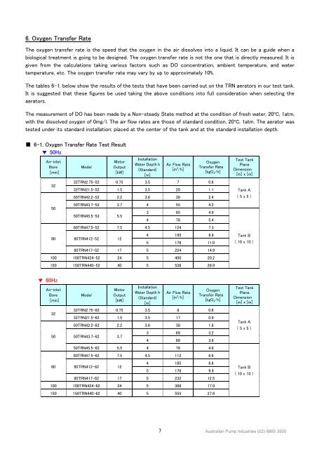
6. Oxygen Transfer RateThe oxygen transfer rate is the speed that the oxygen in the air dissolves into a liquid. It can be a guide when abiological treatment is going to be designed. The oxygen transfer rate is not the one that is directly measured. It isgiven from the calculations taking various factors such as DO concentration, ambient temperature, and watertemperature, etc. The oxygen transfer rate may vary by up to approximately 10%.The tables 6-1. below show the results of the tests that have been carried out on the TRN aerators in our test tank.It is suggested that these figures be used taking the above conditions into full consideration when selecting theaerators.The measurement of DO has been made by a Non-steady State method at the condition of fresh water, 20 o C, 1atm,with the dissolved oxygen of 0mg/l. The air flow rates are those of standard condition, 20 o C, 1atm. The aerator wastested under its standard installation; placed at the center of the tank and at the standard installation depth.■ 6–1. Oxygen Transfer Rate Test Result▼ 50HzAir-inletBore[mm]ModelMotorOutput[kW]InstallationWater Depth h(Standard)[m]Air Flow Rate[m 3 /h]OxygenTransfer Rate[kgO 2 /h]3232TRN2.75-52 0.75 3.5 7 0.632TRN21.5-52 1.5 3.5 20 1.150TRN42.2-52 2.2 3.6 39 2.450TRN43.7-52 3.7 4 55 4.2503 95 4.950TRN45.5-52 5.54 78 5.480TRN47.5-52 7.5 4.5 124 7.380 80TRN412-52 124 195 9.95 178 11.080TRN417-52 17 5 224 14.9100 100TRN424-52 24 5 400 20.2150 150TRN440-52 40 5 538 28.9Test TankPlaneDimension[m] x [m]Tank A( 5 x 5 )Tank B( 10 x 10 )▼ 60HzAir-inletBore[mm]ModelMotorOutput[kW]InstallationWater Depth h(Standard)[m]Air Flow Rate[m 3 /h]OxygenTransfer Rate[kgO 2 /h]3232TRN2.75-62 0.75 3.5 8 0.632TRN21.5-62 1.5 3.5 17 0.950TRN42.2-62 2.2 3.6 38 1.850 50TRN43.7-62 3.73 69 3.24 60 3.650TRN45.5-62 5.5 4 79 4.880TRN47.5-62 7.5 4.5 112 6.680 80TRN412-62 124 185 8.65 176 9.980TRN417-62 17 5 232 12.5100 100TRN424-62 24 5 368 17.9150 150TRN440-62 40 5 555 27.6Test TankPlaneDimension[m] x [m]Tank A( 5 x 5 )Tank B( 10 x 10 )7Australian Pump Industries (02) 8865 3500