Digital HF/VHF/UHF Scanning Direction Finder ... - Rohde & Schwarz
Digital HF/VHF/UHF Scanning Direction Finder ... - Rohde & Schwarz
Digital HF/VHF/UHF Scanning Direction Finder ... - Rohde & Schwarz

Create successful ePaper yourself
Turn your PDF publications into a flip-book with our unique Google optimized e-Paper software.
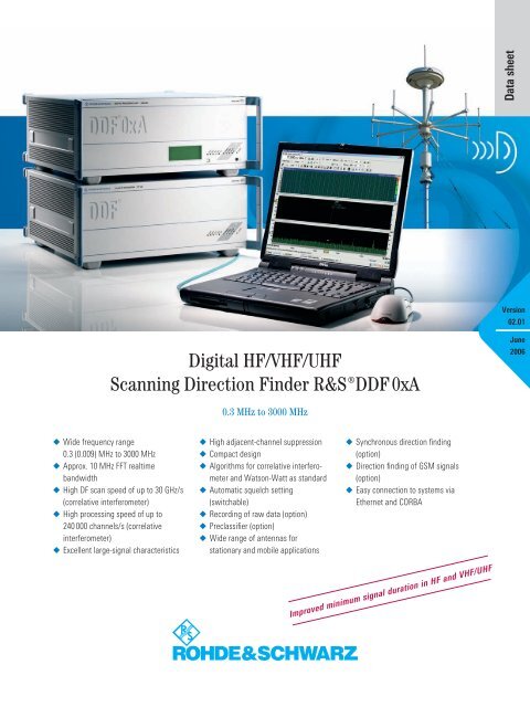
Data sheetVersion02.01<strong>Digital</strong> <strong>HF</strong>/V<strong>HF</strong>/U<strong>HF</strong><strong>Scanning</strong> <strong>Direction</strong> <strong>Finder</strong> ¸DDF 0xAJune20060.3 MHz to 3000 MHz◆◆◆◆◆Wide frequency range0.3 (0.009) MHz to 3000 MHzApprox. 10 MHz FFT realtimebandwidthHigh DF scan speed of up to 30 GHz/s(correlative interferometer)High processing speed of up to240 000 channels/s (correlativeinterferometer)Excellent large-signal characteristics◆◆◆◆◆◆◆High adjacent-channel suppressionCompact designAlgorithms for correlative interferometerand Watson-Watt as standardAutomatic squelch setting(switchable)Recording of raw data (option)Preclassifier (option)Wide range of antennas forstationary and mobile applications◆ Synchronous direction finding(option)◆ <strong>Direction</strong> finding of GSM signals(option)◆ Easy connection to systems viaEthernet and CORBAImproved minimum signal duration in <strong>HF</strong> and V<strong>HF</strong>/U<strong>HF</strong>
Correlative interferometerThe correlative interferometer has the followingadvantages over classic methods:◆◆◆Reduction of DF errors caused byreflections and depolarizationDetermination of a reliable DF qualitycriterion for evaluating and filteringbearingsPossibility of using wide-aperture DFantennas with a minimum number ofantenna elements (preferably a circulararray)The essential features of the Watson-Watt method are:◆ Maximum scan/DF speed with threepathevaluation (only one measurementstep required)◆ Use of small-size antennas in the <strong>HF</strong>range◆ Easy adaptation of existing Adcockantennas (especially in the <strong>HF</strong> range)GeneralThe ¸DDF 0xA family with its extremelyhigh scan speed is the latestgeneration of <strong>Rohde</strong> & <strong>Schwarz</strong> scanningdirection finders. It consists ofpure <strong>HF</strong> (¸DDF 01A) and V<strong>HF</strong>/U<strong>HF</strong>(¸DDF 05A) direction finders as wellas the tried-and-tested combined <strong>HF</strong>/V<strong>HF</strong>/U<strong>HF</strong> direction finders (¸DDF 06A).The combination of the ¸DDF 05AV<strong>HF</strong>/U<strong>HF</strong> direction finder and the¸DDF A-WB <strong>HF</strong> wideband option fordirect receiving mode results in an extremelycompact <strong>HF</strong>/V<strong>HF</strong>/U<strong>HF</strong> full-rangedirection finder.<strong>Digital</strong> DF methodsThe acronym DDF in the type designation¸DDF 0xA stands for digital directionfinder, indicating that bearingsare determined digitally, i.e. the complexantenna voltages are measured bya high-quality three-channel DF receiverthat acts like a vector analyzer andare subsequently digitized. The bearingsof all individual signals are evaluatedin parallel and independently usingmathematical algorithms. Both classicdirection finding methods such as Watson-Wattand the modern correlativeinterferometer can be used.All antennas of the ¸ADDx line plusthe Antenna Interface ¸GX060 canbe used.<strong>Digital</strong> <strong>HF</strong>/V<strong>HF</strong>/U<strong>HF</strong> <strong>Scanning</strong> <strong>Direction</strong> <strong>Finder</strong> ¸DDF 0xA
Functions and applications◆◆◆◆◆◆Automatic DF and location systemswith high probability of interceptInterception and direction finding offrequency-hopping and burst signalsusing automatic evaluation methodsInternal data reduction to limit resultsto targets truly of interest (directionselectivescan), thus ensuring optimizeduse in automatic interceptionsystemsSegmentation of bearings by meansof ¸DDF-CL emitter preclassifier(option) and assignment of tasks tohand-off receiversWith correlation-based evaluation,also calculation of elevation in the <strong>HF</strong>range; implementation of single stationlocation (SSL) systemsVersatile stationary and mobile applications(vehicle, ship, aircraft) by selectingthe appropriate DF algorithmsand antenna configurations, especiallythose with wide-aperture characteristicsType Application Frequency range¸DDF 01A <strong>HF</strong> 0.3 MHz to 30 MHz¸DDF 05A V<strong>HF</strong>/U<strong>HF</strong> 20 MHz to 1300 MHz20 MHz to 3000 MHzdepending on antenna configuration¸DDF 06A <strong>HF</strong>/V<strong>HF</strong>/U<strong>HF</strong> 0.3 MHz to 1300 MHz0.3 MHz to 3000 MHzdepending on antenna configuration¸DDF 05A plus¸DDF A-WB<strong>HF</strong> 1) /V<strong>HF</strong>/U<strong>HF</strong>0.3 MHz to 3000 MHz1) <strong>HF</strong>: direct receiving mode.System configurationThe <strong>Digital</strong> <strong>Scanning</strong> <strong>Direction</strong> <strong>Finder</strong>s¸DDF 0xA cover the <strong>HF</strong>/V<strong>HF</strong>/U<strong>HF</strong> frequency range from 0.3 MHz to1300 MHz/3000 MHz with only a few DFantennas.The direction finders are assigned differenttype designations for different frequencyranges (see table above).Each direction finder basically consistsof four functional units:◆◆◆◆DF antenna systemDF converter with integrated threepathDF receiver modules<strong>Digital</strong> signal processing unitControl PC and softwareThe DF equipment for the <strong>HF</strong> range consistsof the <strong>HF</strong> DF Converter ¸EH110 andthe <strong>Digital</strong> Processing Unit ¸EBD660.For the V<strong>HF</strong>/U<strong>HF</strong> range, the V<strong>HF</strong>/U<strong>HF</strong>DF Converter ¸ET550 (20 MHz to3000 MHz) and the <strong>Digital</strong> Processing Unit¸EBD660 are used. It is also possibleto configure a combination that coversthe entire frequency range (0.3 MHz to3000 MHz).Three DF methods implementedThe software of the digital signal processingunit contains as standard the algorithmsfor DF evaluation according tothe Watson-Watt method, the correlativeinterferometer and the vector matchingmethod. It is thus possible to use any ofthe evaluation methods depending on theavailable antenna system and the operationalrequirements.Receiver123DF processorADDSPA1-9ϕ1-9α / εWNSAzimuth αElevation εEThe <strong>Digital</strong> <strong>Scanning</strong> <strong>Direction</strong> <strong>Finder</strong>s¸DDF 0xA are equipped with built-intest equipment (BITE) by which defectscan be localized partly down to modulelevel.Software updates can be made on thecontrol PC (e.g. via the Internet, and alsoin remote operation).Block diagram of the ¸DDF 0xA<strong>Digital</strong> <strong>HF</strong>/V<strong>HF</strong>/U<strong>HF</strong> <strong>Scanning</strong> <strong>Direction</strong> <strong>Finder</strong> ¸DDF 0xA
Operating and display conceptThe direction finders of the¸DDF 0xA family have no control ordisplay elements. They are controlledfrom an external PC that is connected tothe DF system via data and control interfaces(LAN). Using the standard softwarethat is supplied with each systemand runs under Windows XP, you cancarry out all control and display functions.The system configuration is to alarge extent recognized automatically(antenna type, compass, options).Four DF modes are available:Scan mode (fast DF scanning)In this mode, predefined frequency rangesor frequency lists are scanned for activitiesat maximum speed. The user entersthe scan range (start and stop frequency)or a list of frequencies to bescanned, a lower and, if required, anupper level threshold and the resolutionbandwidth. It is also possible to defineseveral scan ranges. Two azimuth sectorsand (in the <strong>HF</strong> range) the elevationrange can be defined. In addition, specificfrequency bands or discrete frequencies(up to 1000) can be suppressed.Extremely high scan speed up to30 GHz/s (see specifications)The wide realtime analysis window isshifted step by step at high speed acrossthe defined frequency range. All signalscaptured in the window are evaluated inparallel, i.e. simultaneously, by means ofan FFT with selectable resolution.DF results can be displayed in severalways:The simplest method is to display DF valuesas dots in the “bearing versus frequency“mode. The “signal level versusfrequency” window below this displayshows the current signal occupancyof the selected frequency range or rangesas well as the signal levels (spectrumdisplay).DF scan speed and channel resolutionThe DF scan speed mainly depends onthe selected channel resolution. Thelower the resolution, the shorter the filtersettling time and the higher the DFscan speed. It is therefore importantto specify the DF scan speed togetherwith the channel resolution.Scan mode<strong>Direction</strong> finding of two frequency hoppers of the latest generation with 500 hops/s in the same frequencyband<strong>Digital</strong> <strong>HF</strong>/V<strong>HF</strong>/U<strong>HF</strong> <strong>Scanning</strong> <strong>Direction</strong> <strong>Finder</strong> ¸DDF 0xA
DF accuracy and sensitivityWhen the ¸DDF 0xA is tested in areal environment, it is impressive for thestable and accurate bearings it deliverseven for weak signals. This fact is due tothe direction finder‘s elaborate designconcept, which is described in the following.Based on the conceptof virtual receiversWideband mode (WFFM)The direction finder was planned fromthe start with high accuracy and sensitivityin mind. Consequently, the decisionwas made in favor of the concept ofvirtual receivers, which offers significantadvantages with respect to the aforementionedprerequisites.New:wideband modeWideband fixed (WFFM)In this mode, the direction finder simultaneouslytakes bearings of all channelsthat fall within the FFT realtime bandwidth.All relevant parameters such aschannel spacing, integration time andDF quality threshold can be directly set.Results can be displayed in several formats,e.g. spectrum display, bearing versusfrequency and waterfall format.New:parallel averaging of all channelsThe WFFM mode in addition offers theinnovative feature of parallel averagingof all channels, which significantly enhancesthe probability of obtaining bearingsof weak signals. Even DSSS signalswithin the noise floor are reliably detectedand their bearings taken.The concept of virtual receivers is characterizedby a large number of antennaelements being successively connectedto a small number of receivers at veryhigh speed, creating the impression thateach antenna element is assigned a receivepath of its own. The decisive advantageis that large DF antennas withmany antenna elements can be usedwithout requiring a corresponding numberof receive paths, which would bevery costly, because the larger the sizeof a DF antenna, the more antenna elementsare required.Number of antenna elementsIn principle, DF antennas with a largernumber of antenna elements can be designedfor larger diameters. But using alarger number of antenna elements offersclear advantages even for DF antennasthat have identical diameters.For example, a nine-element DF antennaprovides higher accuracy and errortolerance than a five-element antennadue to the fact that it delivers nearlytwice as many antenna signals to beaveraged.<strong>Digital</strong> <strong>HF</strong>/V<strong>HF</strong>/U<strong>HF</strong> <strong>Scanning</strong> <strong>Direction</strong> <strong>Finder</strong> ¸DDF 0xA
Larger DF antenna=enhanced accuracy and sensitivityIt is generally known that a directionfinder‘s accuracy and sensitivity in areal environment increase with the diameterof the DF antenna. As alreadymentioned, this advantage comes intoits own only in a real operational environment,which involves reflectionsand weak signals. It is not obvious fromspecifications, since in data sheets theinstrument and system accuracy arespecified for ideal, non-reflecting DF antennaenvironments and strong signalsto provide comparability. The figure inthe middle shows that the ¸DDF 0xA,featuring a nine-element array and employingthe correlative interferometer DFmethod, offers by far the largest DF antennaand thus higher accuracy and sensitivity.Immunity to reflectionsReflections may basically impair DFaccuracy. Depending on their concept,some DF antennas can handlereflections better than others. The¸DDF 0xA was designed to provideaccurate bearings even with a50 % share of reflections of the incomingsignal. This high immunity to reflectionsis due to the large number of antennaelements used.4 elementsAdcock/Watson-WattD/λ = 0.28 elementsAdcock/Watson-WattD/λ = 1.05 elementsCorrelative interferometerD/λ = 2.09 elements¸DDF0xA correlative interferometerD/λ = 4.3Maximum permissible diameter of the DF antenna relative to the wavelength for unambiguous DF results for up to 50 % of environmental reflectionsImprovement factor relative to narrow-aperture DF systems80706050403020105 antenna elements9 antenna elementsThe figure opposite shows the improvementin DF accuracy as a function of theDF antenna aperture. The enhanced accuracyand sensitivity of the ¸DDF 0xAmakes it especially suitable for takingbearings◆ of weak signals◆ of spread spectrum or DSSS signalswithin the noise floor◆ with high accuracy even in non-idealantenna environments◆ in extremely adverse environments,e.g. urban areas00.51 1.5 2 2.5 3 3.5 4 4.5 5Diameter relative to wavelength D/λImprovement factor as a function of the DF antenna aperture for the correlative interferometer<strong>Digital</strong> <strong>HF</strong>/V<strong>HF</strong>/U<strong>HF</strong> <strong>Scanning</strong> <strong>Direction</strong> <strong>Finder</strong> ¸DDF 0xA
Innovation:averaging in scan modeBy using averaging during broadband directionfinding, a function currently unrivaled,the ¸DDF 0xA reliably detectsand takes bearings of signals such asDSSS even if they occur within the noisefloor. The ¸DDF 0xA is thus well preparedfor this type of data transmission,which is becoming more and more common.The figure opposite shows a bearing beingtaken of a DSSS signal within thenoise floor (–6 dB), the signal having awidth of approx. 5.5 MHz and a nominalbearing value of 48°. The DSSS signal isnot recognizable in the spectrum as thesignal-to-noise ratio is negative. Anotherremarkable feature is the very narrowbearing histogram, which indicates verylow bearing fluctuation and thus a reliablebearing value.High sensitivity for maximum rangeand coverageThe ¸DDF 0xA is also remarkable forits sensitivity: From <strong>HF</strong> to 1.3 GHz, a lowfield strength of typically 0.2 μV/m (<strong>HF</strong>)to 1 μV/m (V<strong>HF</strong>/U<strong>HF</strong>) will suffice to obtaina stable bearing. Above 1.3 GHz, nomore than 3 μV/m to 10 μV/m is needed.This makes the ¸DDF 0xA one of themost sensitive direction finders availableon the market, which is also due to itslarge DF antenna.DSSS signal within noise floor (–6 dB)DF sensitivityDSSS signal withinnoise floorAt present, there exists no uniformmethod of measuring and specifying DFsensitivity. It is therefore of vital importancethat precise information be givenabout the measurement method employed.Specifying DF sensitivity withoutgiving any information about the measurementmethod by which the specifiedsensitivity was obtained is meaningless,as different methods will producesignificantly different results. For<strong>Rohde</strong> & <strong>Schwarz</strong> products, DF sensitivityis defined as the minimum field strengthrequired by the direction finder togetherwith the DF antenna in order to yield accuratebearings (see diagrams on page19, “Sensitivity of DF antennas”).The higher the sensitivity, the wider therange of a direction finder. This is shownby the figure below, which comparestwo DF systems of different sensitivity.The comparison is based on the equationsfor radio propagation in the V<strong>HF</strong>range recommended by ITU.According to these equations, the¸DDF 05A reliably determines thebearing of a 1 W V<strong>HF</strong> transmitter with aline of sight up to a distance of typically30 km. For a DF system of lower sensitivity,the distance has to be reduced, andjust a few μV/m already mean a significantreduction in DF range.V<strong>HF</strong> transmitter with 1 W effectivetransmit power and 2 m antenna heightDF system withtypically 1 µV/msensitivity such asthe ¸DDF05Aapprox. 30 kmapprox. 17 kmDF system withtypically 3 µV/msensitivityRange comparison of DF systems of different sensitivity for a V<strong>HF</strong> transmission<strong>Digital</strong> <strong>HF</strong>/V<strong>HF</strong>/U<strong>HF</strong> <strong>Scanning</strong> <strong>Direction</strong> <strong>Finder</strong> ¸DDF 0xA
High coverage reduces costsThe high sensitivity of the ¸DDF 0xAprovides significantly wider coverage.This means that fewer direction findersare needed for monitoring a specific areathan would be in the case of less sensitiveDF systems, although sensitivity maydiffer by just a few μV/m.¸DDF05A 1¸DDF05A 2¸DDF05A 3 ¸DDF05A 4DF 1 DF 2 DF 3DF 4 DF 5 DF 6DF 7 DF 8 DF 9This substantially reduces costs, as canbe seen from the figure opposite.Spatial coverage with atypical sensitivity of 1 µV/mas with the ¸DDF0xASpatial coverage with atypical sensitivity of 3 µV/mCoverage comparison of DF systems of different sensitivity for a V<strong>HF</strong> transmissionReceiver qualityWhether weak signals can be receivedat all or whether a direction finder candeliver meaningful results, even whenlocated at an unfavorable site in the vicinityof a strong transmitter, largely dependson the quality of the receiversused.Enhanced immunity tostrong signals because ofmaximum linearity andminimum phase noiseLinearity, which is defined by the second-and third-order intercept (SOI andTOI) points, describes to what extentintermodulation products in the vicinityof strong transmitters become visible.Unfortunately, standardized proceduresfor measuring SOI and TOI are notyet available. This makes it difficult tocompare the quality of different receiverson the basis of data sheet specifications.Where comparable measurementsare available, the ¸DDF 0xA receiversfrequently have significantly higherand thus better values.The very low phase noise additionally increasesimmunity to strong signals.And here another advantage of the virtualreceiver concept comes into play:the fact that only a small number of receivepaths is required. The DF converterof the ¸DDF0 xA contains three coherentreceive paths. Compared withfive-path direction finders, this conceptalone reduces costs by 40 %. This in turnmakes it possible to use receivers of superiorquality.The vital prerequisite:state-of-the-art receiversEach ¸DDF 0xA version is equippedwith three receivers that are among thebest available on the world market andhave been developed and produced by<strong>Rohde</strong> & <strong>Schwarz</strong> itself:◆◆The converter for the <strong>HF</strong> range containsthree receivers nearly identicalin design with the ¸EM010The converter for the V<strong>HF</strong>/U<strong>HF</strong> rangecontains three receivers nearly identicalin design with the ¸EM050Finding a suitable location for a DF antennais often difficult, in particular inthe V<strong>HF</strong>/U<strong>HF</strong> range, because strongtransmitters, e.g. FM or TV broadcasttransmitters, may be located nearby. The¸DDF 0xA‘s high linearity and verylow phase noise make it possible to installthe direction finder closer to strongtransmitters.High linearity makes findinga suitable DF location easierSimulations show that, with intermodulationproducts of equal strength, the¸DDF 0xA can be located approx.30 % closer to a strong transmitter thana direction finder whose intercept pointsare approx. 10 dB lower. Compared witha direction finder with 18 dB lower interceptpoints, the ¸DDF 0xA can be installedat even half the distance. Thisfacilitates finding a suitable DF antennasite.<strong>Digital</strong> <strong>HF</strong>/V<strong>HF</strong>/U<strong>HF</strong> <strong>Scanning</strong> <strong>Direction</strong> <strong>Finder</strong> ¸DDF 0xA
Typical applications of the¸DDF 0xA direction finderAutomatic location of LPI transmittersSeveral ¸DDF 0xA direction finderscan be combined to form a DF network,where the direction finders scan a specificfrequency range continuously and synchronouslyand automatically preclassifyand locate transmitters of interest. All locatedtransmitter sites are automaticallydisplayed on an electronic map. Thetransmitters are color-coded to differentiatebetween frequency hoppers, chirp,burst and fixed frequency transmitters.Two DF options are required to ensure reliableautomatic direction finding and location:The ¸DDF-TS option synchronizes theDF process by means of a GPS signal sothat all direction finders of a DF networkscan exactly at the same frequency at thesame time. This is the only way to ensurethat bearings of a short-term emission aretaken by all direction finders, an essentialprerequisite for subsequent location.¸ScanLoc including three ¸DDF 05A direction findersThe high data reduction also means thatrequirements on the data rate of thecommunications link are less stringent.Frequency-agile and crypto radiocommunicationsequipment can thus easily beused for data transmission.Automatic generationand updating ofcommunications order of battleAll radiolocation results are automaticallydisplayed on an electronic map andupdated at a settable refresh rate. Differenttypes of signals, e.g. hoppers orbursts, are represented by different symbols.The DF sites are also marked.The automatic generation and updatingof a communications order of battle includingtracking is the prerequisite formaking fast and reliable decisions.Automatic preclassificationof LPI signalsThe ¸DDF 0xA uses the ¸DDF‐CLoption to store all results and comparethem to new results. LPI signals withtheir characteristic patterns are thus automaticallydetected and classified. Theindividual results of an emission are summarizedto give a condensed result. Thismeans that the overall DF result is compressedto the maximum possible extent,yielding, for example, the informationthat a frequency hopper is transmittedat such and such a frequency, in suchand such a direction and at such andsuch a time.¸ScanLoc DF mapProduct¸DDF 05A¸ADD050¸ADD153¸ADD053¸ADD070¸DDF-CL¸DDF-TS¸DDF A-MCBrief descriptionVery fast V<strong>HF</strong>/U<strong>HF</strong> scanning direction finder with high accuracy and sensitivityV<strong>HF</strong> DF antenna for the frequency range 20 MHz to 200 MHzV<strong>HF</strong>/U<strong>HF</strong> DF antenna for the frequency range 20 MHz to 1300 MHzDF antenna system for the frequency range 20 MHz to 1300 MHz consisting ofthe ¸ADD050 and the ¸ADD153DF antenna for the frequency range 1300 MHz to 3000 MHzDF option for the automatic detection and direction finding of LPI signals such ashoppers, chirps and burstsDF option for synchronizing the scan activities of several direction finders in aradiolocation networkDF option for ¸ScanLoc and multi-user systems; includes the remote-controloption10 <strong>Digital</strong> <strong>HF</strong>/V<strong>HF</strong>/U<strong>HF</strong> <strong>Scanning</strong> <strong>Direction</strong> <strong>Finder</strong> ¸DDF 0xA
installed on a mast, but delivers verygood results also when mounted on avehicle roof.The DF Antenna ¸ADD119 was developedfor mobile <strong>HF</strong> direction finding.The antenna consists of a crossed loopand a reference antenna, which combineto form a classic Watson-Watt DF antennaapprox. 1 m in diameter. The antennais designed for ground waves upto 30 MHz and, despite its small dimensions,offers a DF accuracy of 2° RMS aswell as high sensitivity. It is preferablyinstalled on a vehicle roof or a tripod.¸DDF 05A with ¸DDF A-WB optionError correction on requestMobile <strong>HF</strong>/V<strong>HF</strong>/U<strong>HF</strong> direction finderTo provide mobile detection and directionfinding throughout the entire frequencyrange up to 1300 MHz, it takescompact DF equipment, broadband DFantennas and appropriate DF methods.300 kHz to 1.3 GHzwith two compact DF antennas<strong>Rohde</strong> & <strong>Schwarz</strong> offers optimized DFequipment and antennas that provideseamless coverage in the frequencyrange 300 kHz to 1300 MHz. The completerange is covered by only two DFantennas that deliver very good resultsdespite their small dimensions. Above200 MHz, the mobile system offers DFaccuracy and sensitivity as high as thatof the stationary system.300 kHz to 3 GHzwith just eight height unitsThe ¸DDF 05A with the ¸DDF A‐WBoption is a highly compact <strong>HF</strong>/V<strong>HF</strong>/U<strong>HF</strong> directionfinder (eight height units), featuringa wide realtime bandwidth through the entirefrequency range. Above 20 MHz, signalprocessing is carried out in the same wayas with the stationary system, i.e. by meansof three preselectors and converters. In the<strong>HF</strong> range, by contrast, the three channelsare switched directly to the A/D convertersof the DF processor, and the receive pathsare implemented in the form of digital softwarereceivers.The V<strong>HF</strong>/U<strong>HF</strong> range is covered by the DFAntenna ¸ADD153. The antenna consistsof nine elements and uses the correlativeinterferometer. It is preferablyWith the antenna mounted on a vehicle,the DF accuracy is generally restrictedby resonances and reflections, especiallyin the range below 200 MHz. To minimizeimpairment of DF quality by sucheffects, <strong>Rohde</strong> & <strong>Schwarz</strong> will on requestcalibrate your DF vehicle on a turntable.With calibration, the DF accuracy in thisrange is on average twice as high aswithout calibration.Product¸DDF 05A¸DDF A-WB¸ADD119¸ADD153¸ADD150A¸AP502Z1Brief descriptionVery fast V<strong>HF</strong>/U<strong>HF</strong> scanning direction finder with high accuracy and sensitivityDF option that extends the V<strong>HF</strong>/U<strong>HF</strong> <strong>Direction</strong> <strong>Finder</strong> ¸DDF 05A to includethe <strong>HF</strong> band and increases the FFT realtime bandwidth to 10 MHzCompact Watson-Watt <strong>HF</strong> DF antennaV<strong>HF</strong>/U<strong>HF</strong> DF antenna for the frequency range 20 MHz to 1300 MHzAdapter for mounting the ¸ADD153 on a mastAdapter for flat-mounting of the ¸ADD119 on a vehicle roofMobile <strong>HF</strong>/V<strong>HF</strong>/U<strong>HF</strong> direction finder from<strong>Rohde</strong> & <strong>Schwarz</strong><strong>Digital</strong> <strong>HF</strong>/V<strong>HF</strong>/U<strong>HF</strong> <strong>Scanning</strong> <strong>Direction</strong> <strong>Finder</strong> ¸DDF 0xA 11
Stationary V<strong>HF</strong>/U<strong>HF</strong> radiomonitoringThe ¸ADD053 antenna systemwas designed for use in stationaryand semimobile V<strong>HF</strong>/U<strong>HF</strong> DF systems.This antenna system together with the¸DDF 05A yields a DF system that offersoutstanding characteristics:◆◆◆Highly accurate bearings due to theuse of large DF antennas with nineelements each: DF accuracy is usually1° RMS even in real environmentsdue to the high immunity to reflectionsExtremely high sensitivity, which islikewise due to the large antenna diameter:a field strength as low as1 μV/m suffices at most frequenciesto provide accurate bearings (see datasheet on DF Antennas ¸ADDx)High scan speed owing to extensivecomputing capacity: scan speed ashigh as 30 GHz/s can be selected¸ADD053 and ¸ADD070 DF antennasystemThe DF Antenna ¸ADD153 is mountedat the top. This antenna covers thefrequency range 200 MHz to 1300 MHz.While the ¸ADD153 can be useddown to 20 MHz, the ¸ADD050 isemployed in this range as it offers betterresults due to its considerably largersize.Maximum accuracy andsensitivity in the tacticalV<strong>HF</strong> rangeThe ¸ADD050 with a diameter of3 m has been optimized for directionfinding in the range 20 MHz to 200 MHz.Together with the ¸ADD153 and aglass-fiber intermediate mast, it formsthe ¸ADD053 antenna system.Mounting the antenna system takes surprisinglylittle time, which is also dueto the extensive use of lightweight constructionmaterial such as aluminum andglass fiber.In field use, the DF system is impressivefor taking extremely accurate bearingsof LPI signals such as hoppers andbursts at an extremely high speed, evenif such signals are transmitted over largedistances and therefore hardly recognizable.If necessary, the DF Antenna¸ADD070 can be added to extendthe coverage range up to 3 GHz.Product¸DDF 05A¸ADD053Brief descriptionVery fast V<strong>HF</strong>/U<strong>HF</strong> scanning direction finder with high accuracy and sensitivityDF antenna system for the frequency range 20 MHz to 1300 MHz consisting ofthe ¸ADD050 and the ¸ADD153¸ADD070 DF antenna for the frequency range 1300 MHz to 3000 MHz, sturdy version (02),permitting the ¸ADD053 to be mounted on its top¸KK500All-weather cabinet for the DF equipmentEspecially when high masts are used orthe control PC is spaced some distanceaway from the DF equipment, it is advisableto accommodate the DF equipmentin the All-Weather Cabinet ¸KK500.This does away with the need for longcoaxial cables, which reduce sensitivityat high frequencies and are very costly.If the Ethernet link is also implementedby means of a glass-fiber cable, thecontrol PC can be installed several hundredmeters away from the DF equipmentwithout any impairment to the DFprocess.12 <strong>Digital</strong> <strong>HF</strong>/V<strong>HF</strong>/U<strong>HF</strong> <strong>Scanning</strong> <strong>Direction</strong> <strong>Finder</strong> ¸DDF 0xA
Semimobile <strong>HF</strong> DF stationIn conjunction with the wide-apertureDF Antenna ¸ADD011, the <strong>Direction</strong><strong>Finder</strong> ¸DDF 01A forms a DF systemfor the frequency range 300 kHz to30 MHz that is remarkable for its highaccuracy and sensitivity.The large nine-element DF antenna of50 m in diameter combines with the correlativeinterferometer to make the directionfinder less sensitive to reflectionsencountered in uneven terrain. Thisgreatly facilitates finding a suitable locationfor the DF antenna.The use of crossed loops ensures thatbearings will still be taken even of signalsincident at steep elevation anglesof up to 85°. The elevation angle is alsocalculated, making the DF antenna ideallysuited for single station location.DF Antenna ¸ADD011Superior accuracy andsensitivityThe ¸DDF 01A combined with the¸ADD011, therefore, offers a typicalDF accuracy of 1° RMS and a typicalsensitivity of 0.25 μV/m (seespecifications) also in real environmentsthat are suitable for direction finding (i.e.not only in an ideal test terrain).Installation of the ¸ADD011 is quickand easy. Trained personnel will need nomore than half an hour to set up the antennaby using the tools supplied.Product¸DDF 01A¸ADD011¸DDF-SSL¸DDF A-REM¸KK500In stationary applications, remote controlof the DF system by means of the¸DDF A-REM option is recommended.This allows the direction finder to belocated in a remote area where impairmentby man-made noise and reflectionsis kept to a minimum.Brief descriptionVery fast <strong>HF</strong> scanning direction finder with high accuracy and sensitivityWide-aperture <strong>HF</strong> DF antenna with high accuracy and sensitivitySingle station locator DF software option for locating <strong>HF</strong> transmitters by meansof only a single direction finder, based on ionosphere dataDF option for remote control of the direction finder via ISDN, etcAll-weather cabinet for the DF equipment<strong>Digital</strong> <strong>HF</strong>/V<strong>HF</strong>/U<strong>HF</strong> <strong>Scanning</strong> <strong>Direction</strong> <strong>Finder</strong> ¸DDF 0xA 13
Options<strong>Direction</strong> finding of GSM mobilephones¸DDF-GSM optionBearing versustimeslot displayWith this option, the ¸DDF 05A enablesquasi-simultaneous direction findingof all mobile phones active in a channel.A bearing is determined for eachoccupied timeslot. Only in this way is itpossible to locate a mobile phone in adensely occupied radio scenario.Reliable bearings in denselyoccupied radio scenariosMobile phones transmit information inshort bursts of 577 μs. Requiring a minimumsignal duration of only 350 μs, the¸DDF 05A is able to capture theseextremely short-term emissions. Themain task of the GSM option is to causethe direction finder to start the measurementexactly when the mobile phonestarts transmitting. This can be done inthree ways:◆◆◆The ¸DDF 05A is synchronized tothe base station to which the mobilephone is connected.An external trigger signal informs the¸DDF 05A of the start of an emission(option).The ¸DDF 05A is supplied with ahighly stable clock signal (e.g. GPS)and synchronized to the base stationonly once. Depending on the stabilityof the external clock signal, the directionfinder remains synchronized tothe base station for many hours.¸DDF-GSM option: control software in GSM mode with eight mobile phonescamouflage radio emissions are becomingmore and more sophisticated.Consequently, the probability increasesthat, for example, frequency hoppersoperating in large bandwidths or shortbursts emitted at unknown frequencieswill go unnoticed.The preclassifier ensures that virtuallyevery signal will be detected.Automatic detection ofhoppers, bursts and chirpsAfter a start and a stop frequency is entered,the frequency range is continuouslyscanned and results are stored.Any new signals detected are comparedwith the results previously stored. If aspecific pattern is recognized (e.g. severalburst emissions from the same direction,indicating a frequency hopper),the signal in question is classified asAutomatic preclassifier¸DDF-CL optionPersonnel involved in military radiomonitoringin particular has to cope with increasinglycomplex radio scenarios. Thespectrum occupancy is steadily increasing,while the techniques employed to¸DDF-CL option: principle of preclassification14 <strong>Digital</strong> <strong>HF</strong>/V<strong>HF</strong>/U<strong>HF</strong> <strong>Scanning</strong> <strong>Direction</strong> <strong>Finder</strong> ¸DDF 0xA
elonging to one of the following categories:fixed frequency, hopper, chirp orburst. Individual results are averaged toform an overall result. The ¸DDF 0xAwith the preclassifier option, therefore,provides the basic functionality neededfor the automatic location of LPI signals.This technique not only offers the advantageof being independent of the operator‘sexpertise, but also another importantasset, i.e. data reduction.¸DDF-<strong>HF</strong>R option: direction finding of two emitters in the same frequency range with 20 HzresolutionMaximum data reductionRadiolocation networks consisting ofseveral direction finders transfer DF resultsto a central station. The smaller theamount of data to be transferred, theless conspicuous the data transmission.Preclassification maximally reduces data,leaving only the essential information tobe transmitted.High frequency resolution¸DDF-<strong>HF</strong>R optionThe ¸DDF 0xA offers high frequencyresolution as standard, which is sufficientfor most applications. Some applications,however, require extremely highresolution, for example:◆ <strong>Direction</strong> finding of co-channel interferers:if two transmitters operate inan overlapping spectrum, the bearingerror increases and the bearing mayeven be invalid.◆ <strong>Direction</strong> finding of hidden signals:the same applies as in the case of cochanneltransmitters. The differenceis that the signal searched for deliberatelyconceals itself in the spectrumof an FM or TV broadcast transmitter,for example.New:extremely high frequencyresolution on requestDue to the extremely high frequency resolutionachieved with the ¸DDF-<strong>HF</strong>Roption, the ¸DDF 0xA calculates upto a hundred times more bearings perfrequency band. As a result, statisticalfunctions such as the histogram and thesliding averaging function yield more accurateresults in considerably less time.Moreover, a greater number of interference-freebearings is obtained since, atthe instant a bearing is taken, only onetransmitter emits a signal at that specificfrequency.The figure above shows a measurementin the WFFM mode with a resolution of20 Hz. In the range marked by the twoorange lines, a co-channel interferer issuperimposed on the signal of interest.Owing to the high resolution, two maximaare clearly discernible in the histogram,and accurate bearings can be taken.Remote control¸DDF A-REM optionThere are two main reasons for operatingthe ¸DDF 0xA by remote control:improved receive characteristics andsimplified control of DF networks.Remote control via virtuallyany data linkImprovement of receive characteristics:Man-made noise is particularly high inthe shortwave range. Setting up a DFsystem at a sufficient distance fromdensely populated areas is therefore crucialwhen bearings are to be taken ofweak signals. To avoid strong reflections,it is further recommended that <strong>HF</strong> directionfinders be set up as far away as possiblefrom buildings, high-tension lines,streets and roads. If the DF operatorsthemselves are not stationed at suchremote locations, remote control is thesolution.¸DDF A-REM option<strong>Digital</strong> <strong>HF</strong>/V<strong>HF</strong>/U<strong>HF</strong> <strong>Scanning</strong> <strong>Direction</strong> <strong>Finder</strong> ¸DDF 0xA 15
Synchronous scanning¸DDF-TS optionTo locate a transmitter by triangulation,bearings are required of several directionfinders. This is ensured for signals withnormal transmission duration of a fewhundred milliseconds and above.A key requirement forlocating LPI signalsWith frequency-agile LPI signals suchas hoppers and bursts, the duration of asingle transmission is very short. Moreover,the frequency is not known, sothat large frequency ranges have to bescanned. It may happen that only one directionfinder is operating at the correctfrequency at the moment of an emission.Locating the transmitter searched for isthen impossible.Using the ¸DDF-TS option, the scanactivities are synchronized, i.e. each directionfinder measures exactly at thesame frequency at the same time. A reliablebearing of any detected signal is takenby each direction finder, and the signalis located with maximum accuracy.Synchronization is highly accurate due tothe use of GPS. The ¸DDF-TS optionis therefore an important prerequisite forDF networks locating LPI signals.Tools for maintenance and troubleshooting¸DDF-SK optionThe ¸DDF-SK service kit option considerablycuts the time required formaintenance and troubleshooting of the¸DDF 0xA.Troubleshooting –fast and successfulAll tools essential for checking the DFsystem are conveniently accommodatedin a rugged case. An important tool is the¸DDF-TS optionAntenna Simulation ¸ZT660, whichis connected to the direction finder insteadof the DF antenna to perform systemtests. It can be set to simulate anydesired <strong>Rohde</strong> & <strong>Schwarz</strong> DF antenna. Usingthe antenna simulation, it can convenientlybe checked whether a fault originatesfrom the DF antenna or the DFequipment. This relieves the operatorfrom having to climb the antenna mast oreven dismount the DF antenna unnecessarily.The antenna simulation also allowsa signal generator to be connected to theDF system, and to take test bearings of itssignals with a predefined direction.The service kit contains the followingtest equipment:◆ Antenna Simulation ¸ZT660◆ Various cables and adapters◆ Various tools for opening housingsand enclosuresThe following tests can be performed,for example:◆ Localization of faults as originatingfrom the DF equipment or DF antenna◆ Testing of the three receive paths◆ Taking a test bearing with the aid ofa signal generatorOutput of digitized raw data¸DDF-DR optionIf the ¸DDF 0xA is used as a datasource for an analysis system such as¸AMMOS, digitized, unprocessed intermediate-frequency(IF) data has to beoutput.New:raw data output for analysisThe ¸DDF-DR option allows raw datato be output via a standardized FPDPinterface. The digitized IF data of thethree receive paths are brought out atthis interface and can be recorded bymeans of the ¸AMREC, for example.ReceiverA/Dconversion¸DDF-DR optionRaw data recording,e.g. with ¸AMRECDF signalprocessing<strong>Digital</strong> <strong>HF</strong>/V<strong>HF</strong>/U<strong>HF</strong> <strong>Scanning</strong> <strong>Direction</strong> <strong>Finder</strong> ¸DDF 0xA 17
Broadband direction finding and<strong>HF</strong> extension¸DDF A-WB optionV<strong>HF</strong>/U<strong>HF</strong> DF antenna<strong>HF</strong> DF antenna<strong>HF</strong> DF antennaThe ¸DDF A-WB option significantlyboosts the already high scan speedin the <strong>HF</strong> range. It expands the realtimebandwidth from 1 MHz to up to 10 MHz,thus providing a considerably higherprobability of intercept for short-termand frequency-agile signals. The complete<strong>HF</strong> band is searched, at good resolution,in less than 100 ms (see specifications).When switchover is made to broadbanddirection finding, the preselectors arebypassed and the antenna signals areapplied directly to the A/D converters.Further signal processing is digital.The ¸DDF A-WB option performsseveral tasks, depending on the baseunit in which it is installed. In the caseof the ¸DDF 01A, the realtime bandwidthis increased to 10 MHz; in thecase of the ¸DDF 05A it additionallyextends the frequency range to includethe <strong>HF</strong> band.PreselectorRF converter¸ET550V<strong>HF</strong>/U<strong>HF</strong> receiver¸EBD660DF processorA/D conversionSoftware receiversand signal processing¸DDF A-WB option to include the <strong>HF</strong>band for the V<strong>HF</strong>/U<strong>HF</strong> <strong>Direction</strong> <strong>Finder</strong>¸DDF 05A:Extremely compact full-rangedirection finderA compact <strong>HF</strong> DF antenna, for examplethe ¸ADD119, is connected to theDF Converter ¸ET550. When V<strong>HF</strong>/U<strong>HF</strong> is selected, the antenna signals arerouted through the preselectors and converters.When <strong>HF</strong> is selected, the antennasignals are directly applied to theA/D converters of the DF processor.After A/D conversion, the signals are furtherprocessed by means of software receivers.Bearings are calculated with10 MHz realtime bandwidth employingthe correlative interferometer or theWatson-Watt method, depending on theDF antenna used.PreselectorRF converter¸EH110<strong>HF</strong> receiver¸EBD660DF processorA/D conversionSoftware receiversand signal processing¸DDF A-WB option to expand therealtime bandwidth for the <strong>HF</strong> <strong>Direction</strong><strong>Finder</strong> ¸DDF 01A:Can be switched betweenmaximum scan speed andmaximum accuracy as requiredThe spectrum can first be scanned atmaximum speed with 10 MHz FFT realtimebandwidth. In this mode, the antennasignals are directly applied to theA/D converters; further signal processingis digital.On detecting a transmitter of interest,switchover is made to the normal mode,and the antenna signals are routedthrough the preselectors and converters.This procedure yields better results especiallyfor weak signals and for locationsin the vicinity of strong transmitters.18 <strong>Digital</strong> <strong>HF</strong>/V<strong>HF</strong>/U<strong>HF</strong> <strong>Scanning</strong> <strong>Direction</strong> <strong>Finder</strong> ¸DDF 0xA
DF antennasThe direction finders of the ¸DDF 0xAfamily operate with the DF Antennas¸ADDx, which are also used forthe ¸DDF 0xM, ¸DDF 0xS and¸DDF 0xE families of direction finders.In many cases, existing DF antennas(especially <strong>HF</strong> Adcock antennas) fromother manufacturers can be used. Inthese cases, the Antenna Interface¸GX060 is required. The details mustbe verified from case to case.Field strength in µV/m161412108Field strength in µV/m43.532.52¸ADD1191.5¸ADD010, ¸ADD011, ¸ADD01210.500 5 10 15 20 25 30Frequency in MHz¸ADD153¸ADD050¸ADD070¸ADD170642010100100010000Frequency in MHzSensitivity of DF antennas;averaging time 1 s, bearing fluctuation
Specifications – <strong>HF</strong> antennasType (Order No.) ¸ADD119 (4053.6509.02) ¸ADD010 (4045.0105.03) ¸ADD011 (4045.0005.13)The figure shows an antenna element of the ¸ADD010, which in totalcontains nine elements arranged on a circle 50 m in diameter.Application mobile, fast scanning for ground waves and sky waves with low elevationangleFrequency range (0.3 MHz) 1 MHz to 30 MHz, below 1 MHz with limited sensitivity and accuracysemimobile and stationary, for signals with elevation angle ≤50°, SSL possibleto a limited extentstationary, for signals with elevation angle ≤85°, SSL possibleAntenna type 1 crossed loop and 1 active dipole active 9-element circular array of rod antennas active 9-element circular array of crossed loop antennasDF method Watson-Watt correlation correlationPolarization vertical vertical vertical, horizontal, circularDF accuracy 1) 2° RMS 1° RMS 1° RMSSensitivity typ. 4 µV/m to 2.5 µV/m (2° bearing fluctuation, 1 kHz bandwidth,1 s averaging time)typ. 1 µV/m to 0.2 µV/m (2° bearing fluctuation, 1 kHz bandwidth,1 s averaging time)typ. 1 µV/m to 0.2 µV/m (2° bearing fluctuation, 1 kHz bandwidth,1 s averaging time)Power supply from DF equipment from power supply built in as standard from power supply built in as standardDimensions (approx.) 1100 mm diameter × 232 mm height antenna circle: 50 m diameter, height of rod antenna: 2 m antenna circle: 50 m diameter, height of crossed loop: 3.5 m incl. tripodColor RAL 1015 RAL 6014 RAL 6014Weight (approx.) 25 kg single element with base plate: 14 kg, network: 22 kg single element with base plate: 32 kg, network: 22 kg1)Measurement in reflection-free environment. The RMS error is calculated from the bearings of an evenly distributed azimuth and frequency sample.20 <strong>Digital</strong> <strong>HF</strong>/V<strong>HF</strong>/U<strong>HF</strong> <strong>Scanning</strong> <strong>Direction</strong> <strong>Finder</strong> ¸DDF 0xA
Specifications – V<strong>HF</strong>/U<strong>HF</strong> antennasType (Order No.) ¸ADD153 (4053.0003.02) ¸ADD050 (4041.4006.02) ¸ADD053 (4062.8800.02) ¸ADD070 (4043.4003.02/.12) 2) ¸ADD070M (4059.6000.02) ¸ADD170 (4055.7502.12)Application V<strong>HF</strong>/U<strong>HF</strong>, mobile and stationary V<strong>HF</strong>, stationary, enhanced accuracyespecially with multipath propagationV<strong>HF</strong>/U<strong>HF</strong>, stationary, combination of¸ADD153 and ¸ADD050U<strong>HF</strong>, stationary, can be mounted belowV<strong>HF</strong>/U<strong>HF</strong> antennas on same mastU<strong>HF</strong>, mobile optimized for mobile direction findingin GSM bandsFrequency range 20 MHz to 1300 MHz 20 MHz to 200 MHz 20 MHz to 1300 MHz 1300 MHz to 3000 MHz 1300 MHz to 3000 MHz 800 MHz to 2000 MHzAntenna type 9 active antenna elements in radome active 9-element circular array 2 × active 9-element circular array 8-element circular array 8-element circular array 8-element circular array with centerantennaDF method correlation correlation correlation correlation correlation correlationPolarization vertical vertical vertical vertical vertical verticalDF accuracy 1) 2° RMS (20 MHz to 200 MHz)1° RMS (200 MHz to 1300 MHz)Sensitivity typ. 8 µV/m to 0.5 µV/m(2° bearing fluctuation, 1 kHz bandwidth,1 s averaging time)Wind load/center of wind loadWithout ice depositWith 30 mm ice depositat 188 km/h: 710 N/210 mmat 162 km/h: 770 N/270 mm1° RMS 1° RMS 2° RMS 2° RMS 2° RMStyp. 2.5 µV/m to 1 µV/m(2° bearing fluctuation, 1 kHz bandwidth,1 s averaging time)at 188 km/h: 1700 N/380 mmat 162 km/h: 2800 N/410 mmtyp. 0.5 µV/m to 1 µV/m(2° bearing fluctuation, 1 kHz bandwidth,1 s averaging time)at 188 km/h: 2700 N/800 mmat 162 km/h: 3700 N/690 mmPower supply from DF equipment from DF equipment, Power Supply ¸IN061 may be required for cableswith a length >20 m (details upon request)Dimensions (approx.) 1100 mm diameter × 297 mm height(height incl. lightning rod: 1327 mm)antenna circle: 3 m diameter,height: 800 mm, with lightningrod: 3 mantenna circle: 3 m diameter,height: 800 mm, with lightningrod: 3 mtyp. 3 µV/m to 10 µV/m(2° bearing fluctuation, 1 kHz bandwidth,1 s averaging time)typ. 3 µV/m to 10 µV/m(2° bearing fluctuation, 1 kHz bandwidth,1 s averaging time)typ. 5 µV/m to 10 µV/m(2° bearing fluctuation, 1 kHz bandwidth,1 s averaging time)at 180 km/h: 200 N/250 mm (model .12) at 200 km/h: 530 N/620 mm (model .02)at 140 km/h: 210 N/260 mm (model .12) at 176 km/h: 530 N/680 mm (model .02)at 180 km/h: 199 N/170 mmat 140 km/h: 160 N/180 mmat 180 km/h: 350 N/180 mmat 140 km/h: 280 N/200 mmfrom DF equipment from DF equipment from DF equipment340 mm diameter × 1200 mm height(model .02)340 mm diameter × 492 mm height(model .12)455 mm diameter × 364 mm height 455 mm diameter × 393 mm heightColor RAL 1015 RAL 1015 RAL 1015 RAL 1015 RAL 1015 RAL 1015Weight (approx.) 30 kg 70 kg 114 kg 90 kg (model .02), 11 kg (model .12) 11 kg 11 kg1)Measurement in reflection-free environment. The RMS error is calculated from the bearings of an evenly distributed azimuth and frequency sample.2)Model .12: lightweight model for mobile use.<strong>Digital</strong> <strong>HF</strong>/V<strong>HF</strong>/U<strong>HF</strong> <strong>Scanning</strong> <strong>Direction</strong> <strong>Finder</strong> ¸DDF 0xA 21
Specifications – ¸DDF 01AFrequency rangeDF methodOperationInstrument DF accuracySystem DF accuracy (in test field)with ¸ADD010 or ¸ADD011DisplayDisplay resolutionDF sensitivityOperating modesInstantaneous bandwidthFrequency span in wideband modeMinimum signal duration 1)(depending on selected FFT realtimebandwidth)Correlative interferometerWatson-WattScan speed with 20 kHz resolution,100 % channel occupancy, BT = 4Correlative interferometerWatson-WattScan speed with 5 kHz resolution,100 % channel occupancy, BT = 4Correlative interferometerWatson-WattProcessing speedCorrelative interferometerWatson-Watt0.3 MHz to 30 MHzcorrelative interferometer, Watson-Wattvia graphical user interface (GUI) onexternal PC with Windows XP0.5° RMS1° RMSazimuth versus frequency, levelversus frequency, polar diagram,histogram, waterfall, realtime IF panoramicdisplay (bandwidth 20 kHzor 1 MHz)0.1° or 1° (selectable)typ. 0.2 µV/m to 0.5 µV/m(see diagram for <strong>HF</strong> DF antennas,page 19)SCAN (f-SCAN, m-SCAN), SEARCH,fixed frequency mode (FFM),wideband mode (WFFM)1 MHz10 MHz/5 MHz/2 MHz with¸DDFA-WB option1 MHz10 MHz/5 MHz/2 MHz with¸DDF A-WB option0.5 MHz/0.2 MHz/0.1 MHz with¸DDF-<strong>HF</strong>R option1 ms0.3 msup to 0.9 GHz/s (incl. calculation ofelevation)with ¸DDF A-WB option:up to 4 GHz/s (incl. calculation of elevation)up to 3.5 GHz/swith ¸DDF A-WB option:up to 11 GHz/sup to 250 MHz/s (incl. calculation ofelevation)with ¸DDF A-WB option:up to 500 MHz/s (incl. calculation ofelevation)up to 1 GHz/swith ¸DDF A-WB option:up to 2 GHz/sup to 50 000 channels/swith ¸DDF A-WB option:up to 200 000 channels/sup to 200 000 channels/swith ¸DDF A-WB option:up to 400 000 channels/sChannel spacing(depending on selected FFT realtimebandwidth)Bandwidths<strong>Direction</strong> findingDemodulationAdjacent channel suppression≥10 kHzModes of demodulationFilter selectivity (shape factor,60 dB/3 dB)Dynamic range (incl. AGC)LinearitySecond-order intercept (SOI)Third-order intercept (TOI) 2)Intermodulation-free dynamic rangePhase noise20 kHz/10 kHz/5 kHz/2 kHz/1 kHz/0.5 kHz/0.2 kHzwith ¸DDF-<strong>HF</strong>R option additionally:0.1 kHz/0.05 kHz/0.02 kHz12 kHz/6 kHz/3 kHz/1.2 kHz/0.6 kHz/0.3 kHz/0.12 kHz20 kHz/12 kHz/10 kHz/6 kHz/3.4 kHz/3 kHz/1.2 kHz/0.6 kHz/0.3 kHz/0.12 kHz/0.06 kHz80 dB (FFM), 60 dB (SCAN)CW, AM, FM, SSB2.5 (FFM)3.6 (SCAN)>120 dB≥75 dBm, typ. 85 dBm≥32 dBm, typ. 39 dBmtyp. 95 dB (in-band, bandwidth of1.2 kHz)95 dB, typ. 110 dBIF rejection>95 dB, typ. 110 dBMTBF¸EBD660¸EH110>24 000 h>60 000 h1) 100 % probability of intercept for a single burst emission within realtime bandwidth.Lower values are possible for measurements performed with multiple burst emissions andreduced probability of intercept.2) Frequency separation between intermodulating signals ≥30 kHz. Higher values are possiblefor measurements performed at larger frequency separation.22 <strong>Digital</strong> <strong>HF</strong>/V<strong>HF</strong>/U<strong>HF</strong> <strong>Scanning</strong> <strong>Direction</strong> <strong>Finder</strong> ¸DDF 0xA
Specifications – ¸DDF 05AFrequency rangeDF methodOperationInstrument DF accuracySystem DF accuracy (in test field)With ¸ADD053With ¸ADD070DisplayDisplay resolutionDF sensitivity20 MHz to 1300 MHz1300 MHz to 3000 MHzOperating modesInstantaneous bandwidthFrequency span in wideband modeMinimum signal duration 1)(depending on selected FFT realtimebandwidth)Correlative interferometerWatson-WattScan speed with 200 kHz resolution,100 % channel occupancy, BT = 4Correlative interferometerWatson-WattScan speed with 25 kHz resolution,100 % channel occupancy, BT = 4Correlative interferometerWatson-WattProcessing speedCorrelative interferometerWatson-WattChannel spacing(depending on selected FFT realtimebandwidth)Bandwidths<strong>Direction</strong> findingDemodulation20 MHz to 3000 MHzcorrelative interferometer, Watson-Wattvia graphical user interface (GUI) onexternal PC with Windows XP0.5° RMS1° RMS2° RMSazimuth versus frequency, levelversus frequency, polar diagram,histogram, waterfall, realtime IF panoramicdisplay (bandwidth 100 kHzor 2 MHz)0.1° or 1° (selectable)typ. 0.5 µV/m to 1 µV/mtyp. 3 µV/m to 10 µV/m(see diagram for V<strong>HF</strong>/U<strong>HF</strong> DF antennas,page 19)SCAN (f-SCAN, m-SCAN), SEARCH,fixed frequency mode (FFM),wideband mode (WFFM)10 MHz (–6 dB)10 MHz/5 MHz/2 MHz;with ¸DDF-<strong>HF</strong>R option additionally:1 MHz/0.5 MHz/0.2 MHz/0.1 MHz350 µs150 µsup to 30 GHz/sup to 80 GHz/sup to 6 GHz/sup to 15 GHz/sup to 240 000 channels/sup to 600 000 channels/s200 kHz/100 kHz/50 kHz/25 kHz/20 kHz/12.5 kHz/10 kHz/8.33 kHz/5 kHz/2 kHz/1 kHz/0.5 kHz/0.2 kHzwith ¸DDF-<strong>HF</strong>R option additionally:1 kHz/0.5 kHz/0.2 kHz/0.1 kHz/0.05 kHz/0.02 kHz60 kHz/30 kHz/15 kHz/12 kHz/7.5 kHz/6 kHz/5 kHz/3 kHz/1.2 kHz/0.6 kHz150 kHz/60 kHz/30 kHz/15 kHz/12 kHz/7.5 kHz/5 kHz/3 kHz/1.2 kHz/0.6 kHzAdjacent channel suppression≥10 kHzModes of demodulationFilter selectivity (shape factor60 dB/3 dB)Dynamic range (incl. AGC)LinearitySecond-order intercept (SOI)Third-order intercept (TOI) 2)Intermodulation-free dynamic rangePhase noise80 dB (FFM), 60 dB (SCAN)CW, AM, FM, SSB2.5 (FFM)3.6 (SCAN)>120 dB≥50 dBm, typ. 63 dBm≥18 dBm, typ. 28 dBmtyp. 85 dB (in-band, bandwidth of7.5 kHz)90 dB, typ. 110 dBIF rejection>95 dB, typ. 110 dBMTBF¸EBD660¸ET550>24 000 h>25 000 h1) 100 % probability of intercept for a single burst emission within realtime bandwidth.Lower values are possible for measurements performed with multiple burst emissions andreduced probability of intercept.2) Frequency separation between intermodulating signals ≥2.2 MHz. Higher values are possiblefor measurements performed at larger frequency separation.<strong>Digital</strong> <strong>HF</strong>/V<strong>HF</strong>/U<strong>HF</strong> <strong>Scanning</strong> <strong>Direction</strong> <strong>Finder</strong> ¸DDF 0xA 23
General data(valid for ¸DDF 01A, ¸DDF 05A and ¸DDF 06A)¸EBD660 ¸EH110 ¸ET550Operating temperature range –10 °C to +55 °C, meets EN 60068-2-1, EN 60068-2-2, MIL-STD-810E Meth. 501.3/502.3Storage temperature range –40 °C to +71 °C, meets EN 60068-2-1, EN 60068-2-2, MIL-STD-810E Meth. 501.3/502.3Humidity/damp heat max. 80 % cycl. test at 25 °C/40 °C, meets EN 60068-2-30max. 95 % rel. humidity, without condensation, meets MIL-STD-810E Meth. 507.3, without cyclic condensationMechanical resistance/shock 30 g, 11 ms semi-sinewave, meets EN 60068-2-2740 g shock spectrum, 45 Hz to 200 Hz, meets MIL-STD-810E, Meth. 516.4VibrationSinusoidalRandom5 Hz to 55 Hz, max. 2 g, 55 Hz to 150 Hz, 0.5 g const., 12 min/(3)axis, meets EN 60068-2-610 Hz to 500 Hz, 1.9 g (RMS), 30 min/(3)axis, meets EN 60068-2-64EMC 30 MHz to 1000 MHz, 30/37 dBµV/m, field strength (emission), meets EN 550220.15 MHz to 30 MHz, class B interference voltage on AC power lines, meets EN 550220 Hz to 2 kHz interference current on AC power lines, meets EN 61000-3-2±8 kV/±4 kV static discharge, meets EN 61000-4-280 MHz to 1000 MHz, 10 V/m field strength (immunity), meets EN 61000-4-3±2 kV/±1 kV transient burst at AC power/signal connection (immunity), meets EN 61000-4-4±2 kV/±1 kV burst (immunity), meets EN 61000-4-50.15 MHz to 80 MHz, 10 V unmod./mod. 80 % AM (1 kHz) on lines, meets EN 61000-4-610 ms/30 %, 100 ms/60 % voltage reduction, 5 s voltage interruption on AC power lines, meets EN 61000-4-11Power supply100 V to 230 V AC, +10 %/–12 %, 47 Hz to 63 HzElectrical safety(meets EN 61010, VDE 0411) max. 350 VA, typ. 300 VA max. 150 VA, typ. 120 VA max. 200 VA, typ. 180 VADimensions (W × H × D)436 mm × 192 mm × 460 mm (19“ × 4 HU)Weight approx. 15 kg approx. 16 kg approx. 18 kg<strong>Digital</strong> <strong>HF</strong>/V<strong>HF</strong>/U<strong>HF</strong> <strong>Scanning</strong> <strong>Direction</strong> <strong>Finder</strong> ¸DDF 0xA 24
Ordering informationOrder designation Type Order No.<strong>Digital</strong> <strong>HF</strong> <strong>Scanning</strong> <strong>Direction</strong> <strong>Finder</strong> ¸DDF 01A 4059.9100.02<strong>Digital</strong> V<strong>HF</strong>/U<strong>HF</strong> <strong>Scanning</strong> <strong>Direction</strong> <strong>Finder</strong> ¸DDF 05A 4059.9200.02<strong>Digital</strong> <strong>HF</strong>/V<strong>HF</strong>/U<strong>HF</strong> <strong>Scanning</strong> <strong>Direction</strong> <strong>Finder</strong> ¸DDF 06A 4059.9300.02Antennas (see separate data sheet) ¸ADDx see tables on pages 20 and 21OptionsMaster Slave Handover ¸RA-MSH 3020.9690.02LF Extension ¸DDF-LF 4060.0348.02<strong>HF</strong> Wideband Module ¸DDFA-WB 4060.0248.02GSM Interception ¸DDF-GSM 4059.9951.02Synchronous <strong>Scanning</strong> ¸DDF-TS 4060.0290.02Raw-Data Recording ¸DDF-DR 4060.0390.02Preclassifier ¸DDF-CL 4059.9900.02Single Station Locator for <strong>HF</strong> ¸DDF-SSL 3020.8864.02Remote Control Extension ¸DDF A-REM 3020.8858.02High-Frequency Resolution ¸DDF-<strong>HF</strong>R on requestService Kit (for maintenance and troubleshooting) ¸DDF-SK 4060.0454.02<strong>Digital</strong> <strong>HF</strong>/V<strong>HF</strong>/U<strong>HF</strong> <strong>Scanning</strong> <strong>Direction</strong> <strong>Finder</strong> ¸DDF 0xA 25
Certified Quality SystemISO 9001DQS REG. NO 1954 QMMore information atwww.rohde-schwarz.com(search term: DDF0xA)Certified Environmental SystemISO 14001DQS REG. NO 1954 UM¸ is a registered trademark of <strong>Rohde</strong> & <strong>Schwarz</strong> GmbH & Co. KG · Trade names are trademarks of the owners · Printed in Germany (Pe ed/we)PD 0758.0374.32 · ¸DDF 0xA · Version 02.01 · June 2006 · Data without tolerance limits is not binding · Subject to changewww.rohde-schwarz.comEurope: +49 1805 12 4242, customersupport@rohde-schwarz.comUSA and Canada: 1-888-837-8772, customer.support@rsa.rohde-schwarz.comAsia: +65 65130488, customersupport.asia@rohde-schwarz.com